May 22, 1995 - R.W. Leven and M. Selent, Chaos Solitons Fractals 4 (1994). 2217. F.A. McRobie and J.M.T. Thompson, Int. J. Bifurc. Chaos 3. (1993) 1343.
22 May 1995 PHYSICS
LETTERS
A
Physics Letters A ZOl(1995) 191-196
Rotating periodic orbits of the parametrically excited pendulum M.J. Clifford ‘, S.R. Bishop Centre for Nonlinear Dynamics and its Applications,
University College London, Cower Street, London WClE 6BT, UK
Received 3 August 1994; revised manuscript received 7 March 1995; accepted for publication 14 March 1995 Communicated by A.P. Fordy
Abstract Rotating orbits in the parametrically excited pendulum are considered. The location of subharmonic orbits shows that there is in general no easily defined lower bound on the forcing amplitude, p, below which rotating orbits cannot exist. This is particularly important if the parametrically excited pendulum is considered in terms of escape from a potential well.
1. Introduction
Recent analytical and numerical investigations into the behaviour of the parametrically excited pendulum described by ~+j3~+(1+pcosot)sin8=O
(1) have tended to concentrate on solutions which do not exceed 8 = f 7r [l-3]. These solutions have been termed oscillatory, swinging, or non-rotating by the various authors, and under such conditions there is considerable similarity with the more general problem of escape from a potential well [4]. Indeed it has been shown that the parametrically excited pendulum is a generic example of a system which permits escape from a symmetric potential well under parametric excitation [5]. The non-rotating behaviour of the parametrically excited pendulum is extremely complex with multiple attractors, stable solutions of
1
Currently at Building Technology Group, Department of Architecture and Planning, Nottingham University, University Park, Nottingham, NG7 2RD, UK.
any period, chaos, and many bifurcations occurring as parameters are varied. Much work is still to be done before a complete understanding of the underlying dynamics of the parametrically excited pendulum can be achieved. As well as non-rotating orbits, the parametrically excited pendulum can perform inverted oscillations (i.e. around 8 = P> and it has been known for a long time that the pendulum can be stabilised in the inverted position [6]. This has been demonstrated experimentally, and in addition it has recently been shown that multiple pendulums can be stabilised in the upside down position [7,8]. Solutions which exceed 8 = f n have been considered [9,10], but no attempt has been made to classify such solutions. This is unfortunate since there is a large region of parameter space where rotating orbits dominate. This paper is a first attempt to produce an albeit partial classification of rotating orbits. Firstly we define a rotating orbit as a solution which goes beyond 6 = f rr. Rotating orbits can be further subdivided into those which rotate in the same direction for all time, (i.e., d(t) > 0 Vt or d(t) < 0 Vt), and those which change direction in the course of their rotation. We call the former
0375-9601/95/$09.50 0 1995 Elsevier Science B.V. All rights reserved SSDIO375-9601(95)00255-l
192
M.J. CZifford, S.R. Bishop/Physics
-II -7.
t
-3
-,
-0.B
-0.B
-0.1
-0.7.
0
0.2
0.4
J 0.6
Letters A 201 (1995) X91-196
which in turn may be distinct from the forcing frequency. Such subharmonic orbits will be discussed in greater detail in Section 3. No distinction is made here between clockwise and anticlockwise rotating orbits, and given the symmetry of the system, if a clockwise rotating orbit exists, then an equivalent mirror image anticlockwise solution must also exist. For this reason, we will concentrate solely on clockwise rotating orbits at moderate values of forcing, p, in line with the experimental observations of others [lo] with the damping, p, taken as 0.1 throughout. This value of damping has been chosen to be representative of behaviour which is apparent for a range of damping. The figure of p = 0.1 compares with other numerical and experimental studies where a coefficient between 0.1 < /3 < 0.015 was considered [11,12]. One way towards a complete classification of rotating orbits would be to utilise braid and knot theory [13,14], to consider the linking properties of rotating orbits with the equilibria at 9=0, and B= -+rr.
o%/Tt ’
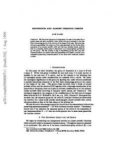
Fig. 1. Phase portraits of a purely rotating and rotating (3,l) orbit. The first is a purely rotating orbit, whilst the other makes an oscillation in the potential well around the equilibrium 8= 0 before rotating beyond B = -n-. Both orbits are unstable, and were located at parameter values o = 2, p = 1.85.
solutions “purely rotating orbits”, and these will be covered exclusively in the following. To clarify the distinction between rotating and purely rotating orbits, we show phase portraits of two period-three orbits in Fig. 1. The first is a purely rotating orbit, whilst the second loops around the equilibrium 8 = 0 before rotating beyond 8 = - 7~. Purely rotating solutions may be categorised according to their period, n, and the number of complete rotations made in n periods of forcing, r. Hence we use the notation (n, r) to describe a period-n orbit which makes r complete rotations in n periods. For example, a period-three solution which rotates twice in three periods of forcing will be termed a (3,2) rotating solution, At first, solutions with n # r seem to be unusual, but just as a nonlinear system can respond at a different frequency to an applied forcing function, so the pendulum can rotate at an average angular frequency distinct from its dynamical period,
2. Bifurcational
bebaviour
The major features of the bifurcational behaviour of the purely rotating (1,l) orbit are displayed in the
I
.5 -
I-
0.5
t
1.5
2
2.5
0
3
Fig. 2. Bifurcation diagram for the clockwise purely rotating orbits in the parametrically excited pendulum. (n, r) period-n orbits rotate completely r times in n periods. Line A is where a period-one (1,l) orbit is formed at a saddle-node bifurcation. This orbit period-doubles at line B to a (2,2) orbit, the beginning of a gradual cascade to rotating chaos. The second period-doubling occurs at line F, which is sufficiently close to represent the end of the cascade before a subsequent bifurcation to tumbling chaos. The period-one orbit restabilises at a rapid reverse period-doubling cascade in the region surrounded by line U.
MJ. Clifford, S.R. Bishop/Physics Letters A 201 (1995) 191-l %
Fig. 3. One quarter of the Poincar.5 section of the purely rotating (not tumbling) chaotic attractor. Parameter values are w = 2, p = 1.81, p = 0.1. This strange attractor is only stable over a very narrow parameter regime before a bifurcation to the tumbling chaotic attractor.
bifurcation diagram of Fig. 2, which was produced by cell mapping [15] to locate solutions, and path following solutions [16] until bifurcations were encountered. These bifurcations were then followed through parameter space. Fig. 2 shows the bifurcational behaviour of the period-one clockwise (1,l) solution. Line A is where the orbit is created at saddle-node bifurcation. This is unusual for parametrically excited systems where a solution usually evolves from some zero solution. However, in this case this is impossible because a (n, r) solution can only bifurcate with other solutions with the same r/n ratio due to topological considerations developed in Ref. [17]. Thus any two rotating and nonrotating solutions cannot bifurcate since a non-rotating solution has r = 0 whilst a rotating solution has r # 0. Below line A no rotating period-one solution exists. Line B is where the (1,l) solution period-doubles to a (2,2) solution at the beginning of a perioddoubling cascade leading to rotating chaos shortly after, and close to the line F. A PoincarC section of the rotating chaotic attractor is shown in Fig. 3. The rotating chaos is only stable over a narrow parameter regime after which it loses stability [11,12], and the trajectories tumble backwards and forwards, rotating clockwise and then anticlockwise in a chaotic fashion. We call this behaviour tumbling chaos. From experimental and numerical studies [11,12] this tumbling chaos is apparent over a broad range in the parameter (p, w) space. In Fig. 2, this region is labelled “Tumbling Chaos” but this does however
193
contain periodic windows which are characteristic of chaotic systems. Furthermore, the zone for w < 1 has not been fully explored in the present work and may contain minor stable solutions and therefore the region as a whole is not shaded. This does not detract from the fact that the tumbling motion is a robust solution which has been viewed by a number of researchers both numerically and experimentally indicating its overall structural stability. The tumbling chaos is, therefore seen as a typical behaviour of the pendulum especially at higher values of the forcing parameter, p. The purely rotating solution restabilises as the tumbling chaos becomes unstable and a very rapid period-doubling cascade in reverse leaves the original (1,l) solution stable in the period-one zone surrounded by line U.
Fig. 4. (a) Portion of chaotic tumbling solution. Parameters are w = 2, p = 2, c = 0.1. (b) Portion of tumbling chaotic trajectory of (a) close to an unstable purely rotating period-two solution.
194
3. Locating subharmonic
MJ. Clifford, S.R. Bishop/Physics
orbits
Whilst the diagram of bifurcations in control space of Fig. 2 encapsulates much of the bifurcational behaviour of purely rotating orbits by considering the bifurcations of the (1,l) solution, there is more to be gained by considering subharmonic orbits. It has already been stated that subharmonic orbits with II # r exist. Numerical evidence suggests that every orbit with r < n, n = 1, 2, 3,. . . exists, and furthermore is stable for some parameter regime. To locate
Letters A 201 (I 995) 191-l 96
subharmonic orbits, we make use of the ergodic properties of chaotic attractors [Ml. Loosely, a chaotic trajectory is essentially a random walk on the unstable periodic orbits which populate the attractor [19]. Sections of the chaotic time history will have strong recurrence properties, and over a short number of periods may appear to be periodic. This is the case if the chaotic trajectory is close to an unstable periodic solution. For example, in Fig. 4, the highlighted portion of tumbling chaotic time history appears to be periodic around an unstable period-two
Fig. 5. Some (n, r) unstable purely rotating orbits for the parametrically excited pendulum located by the method of close returns. Angular velocity is plotted against time over six periods of parametric forcing. Parameters are OJ= 2, p = 1.85.
MJ. Clifford, S.R. Bishop/Physics
orbit. These nearly periodic sections of time history of the tumbling chaotic attractor can be used to approximate the near-by periodic solution. By considering longer portions of chaotic trajectory, many periodic orbits can be approximated, and it has been shown that this technique is very efficient at extracting periodic orbits from chaotic data, and is termed the method of close returns [20-221. If further precision is required, these recurrent sections of the chaotic time series can be used as the initial guess for a Newton-Raphson procedure to pinpoint the unstable periodic orbit. This procedure was carried out for the parametrically excited pendulum for orbits up to period-three, at parameter values p = 1.85, w = 2, and some of the periodic orbits located are shown in Fig. 5. We remark that this procedure is not exhaustive, and orbits not contained in the chaotic region of phase space may be overlooked. Locating higher order periodic orbits is also possible, and orbits up to period-seven have been located by this technique, but as the number of solutions increases with the period and the higher periodic orbits are harder to find due to the eigenvalues of the Jacobian increasing exponentially with period. Solutions with n = 4 and higher have been located, and studies could equally be made of these orbits, but instead we concentrate on the period-three orbits to illustrate the existence of subharmonic solutions below line A in Fig. 2 Computationally, no orbit has been found with r > n, and so we comment that from the numerical evidence it appears that the parametrically excited pendulum cannot rotate with a mean frequency greater than that of the forcing, excluding transient behaviour although we cannot find any physical reason why this should be so. The higher the period, the smaller the stable parameter regime, but it should be borne in mind that unstable orbits are easily controllable by modem nonlinear control techniques 1231, and so the existence of these orbits is of engineering interest. The period-three orbits located by the close returns method are unstable, but by path following these unstable solutions, stable solutions are encountered. The bifurcations that create all the period-three solutions are of the saddle-node variety, and the stable orbits undergo successive period-doubling bifurcations before losing stability at catastrophic bifurcations. These bifurcations were fol-
195
Letters A 201 (1995) I91 -1%
0 0.5
I 1
1.5
2
1.5
0
’
Fig. 6. Bifurcation diagram for the clockwise purely rotating orbits in the parametrically excited pendulum. (n, r) period-n orbits rotate completely r times in n periods. Line A is where a period-one (1,l) orbit is formed at a saddle-node bifurcation. This orbit period-doubles at line B to a (2,2) orbit, the beginning of a gradual cascade to rotating chaos. The second period-doubling occurs at line F, which is sufftciently close to represent the end of the cascade before a subsequent bifurcation to tumbling chaos. The period-one orbit restabilises at a rapid reverse period-doubling cascade in the region surrounded by line U. Additionally, two period-three zones are shown. These are bounded by saddlenode and period-doubling bifurcations. Note that the (3,l) orbits can exist below line A. (3,2) orbits also exist, but are stable over a very narrow parameter regime between the (3,l) and (3,3) zones.
lowed in parameter space. Whilst the parameter ranges over which particular subharmonic rotating solutions are stable are small, these zones are considerably larger than for the equivalent non-rotating solutions discovered in an earlier paper [2]. Fig. 6 shows two zones of subharmonic period-three windows (3,l) and (3,3) overlaid on the major bifurcation diagram in control parameter space. The subharmonies are each bounded by a saddle-node and a period-doubling cascade. We note that especially at high frequency, the regions are quite broad. Stable (3,2) solutions were also path followed, but exist over much narrower parameter ranges.
5. Conclusions We have shown that many different purely rotating solutions exist for the parametrically excited pendulum which can be located by the method of close returns. One of the consequences of the existence of subharmonic solutions is that stable (3,l) subharmonic orbits exist below line A in Fig. 2, which, for physical systems has two consequences. If
196
M.J. Cliffor
S. R. Bishop/Physics
we simply require a rotating solution, then we may be able to achieve this aim through establishing a subharmonic orbit using slightly less force for a given frequency than required for a harmonic solution. On the other hand if we explicitly wish to avoid rotating solutions then there seems, in general, to be no easily determined forcing amplitude, p, that we must not exceed. This has particular importance if we couch the parametrically excited pendulum in terms of the problem of escape from a potential well. This particular aspect warrants further study as it seems intuitive that a lower bound does exist, at least for moderate ranges of driving frequency, which could be obtained by energy considerations. If such a bound exists then this would depend upon the damping with a decrease in the damping producing a reduced lower bound.
Acknowledgement The authors would like to acknowledge the financial support of the Engineering and Physical Sciences Research Council UK, and the referees for their comments.
References [l] P.J. Bryant and J.W. Miles, J. Aust. Math. Sot. Ser. B 32 (1990) 42. [2] S.R. Bishop and M.J. Clifford, Eur. J. Mech. A 12 (1994) 581.
Lefters A 201 (1995) I91 -196 [3] M.J. Clifford and S.R. Bishop, Locating oscillatory orbits of the parametrically excited pendulum, to appear in: J. Aust. Math. Sot. Ser. B. [4] J.M.T. Thompson, Proc. R. Sot. A 421 (1989) 195. [5] M.J. Clifford and S.R. Bishop, Phys. Lett. A. 184 (1993) 57. [6] A. Stephenson, Mem. Proc. Manch. Lit. Philos. Sot. 52 (1908) 1. [7] D.J. Acheson and T. Mullin, Nature 366 (1993) 215. [8] D.J. Acheson, Proc. R. Sot. A 443 (1993) 239. [9] B.P. Koch and R.W. Leven, Physica D 16 (1985) 1. [lo] R.W. Leven, B. Pompe, C. Wilke and B.P. Koch, Physica D 16 (1985) 371. 1111R.W. Leven, M. Selent and D. Uhrlandt, Chaos Solitons Fractals 4 (1994) 661. WI R.W. Leven and M. Selent, Chaos Solitons Fractals 4 (1994) 2217. 1131F.A. McRobie and J.M.T. Thompson, Int. J. Bifurc. Chaos 3 (1993) 1343. 1141J.S. Birman, Braids, links, and linking class groups, Ann. Math. Study 82 (1974). [151C.S. Hsu, Cell to cell mapping: a method of global analysis for nonlinear systems (Springer, Berlin, 1989). [I61S. Foale and J.M.T. Thompson, Comput. Meth. Appl. Mech. Eng. 89 (1991) 381. The parametrically excited pendulum: a 1171M.J. Clifford, paradigm of nonlinear systems, Thesis (1994). 1181J.P. Eckmann and D. Ruelle, Rev. Mod. Phys. 57 (1985) 617. iI91N.B. Tufillaro, T. Abbott and J. Reilly, An experimental approach to nonlinear dynamics and chaos (Addison Wesley, New York, 1992). DO1 N.B. Tufillaro, R. Holzner, L. Flepp, E. Brun, M. Finardi and R. Badii, Phys. Rev. A 44 (1991) 4786. WI A. Fioretti, F. Molesti, B. Zambon, E. Arimondo and F. Papoff, Int. 3. Bifurc. Chaos 3 (1993) 559. P21 M. Lefranc and P. Glorieux, Int. J. Bifurc. Chaos 3 (1993) 643 [231T. Shinbrot, C. Grebogi, (1993) 411.
E. Ott and J.A. Yorke, Nature 363