Abstract- The performance of a speed sensorless variable structure direct torque controlled interior permanent magnet synchronous motor drive at very low ...
Rotor Position and Speed Estimation of a Variable Structure Direct Torque Controlled IPM Synchronous Motor Drive at Very Low Speeds S. Sayeef, G. Foo and M. F. Rahman School of Electrical Engineering, University of New South Wales, Sydney, Australia Abstract- The performance of a speed sensorless variable structure direct torque controlled interior permanent magnet synchronous motor drive at very low speeds including standstill is investigated in this paper. The rotor position and speed are estimated using a high frequency signal injection algorithm at low speeds and a sliding observer at medium to high speeds. The changeover between these two algorithms is performed using a weighting function which smoothly hands over estimated flux and speed information for torque estimation and speed feedback purposes respectively. Experiments were performed to test the effectiveness of the proposed high frequency signal injection algorithm and results show that the sensorless drive is capable of accurately estimating position and speed at very low speeds including standstill.
I.
INTRODUCTION
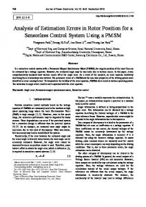
Direct torque control (DTC) for induction motor drives was first proposed in the 1980s by Depenbrock [1] and Takahashi [2]. This concept was also applied to interior permanent magnet synchronous machines (IPMSM) in the late 1990s [35]. When compared to conventional Field Oriented Control (FOC) drives, DTC possesses several advantages, which include fast torque and stator flux dynamics, the elimination of the dq-axis current controllers, associated coordinate transformation, the rotor position sensor requirement and separate voltage pulse width modulator [6]. However, DTC has its own drawbacks, which include high torque, flux and current ripples, variable switching frequency behavior and difficulty to control torque and flux at very low speed. As the switching state of the inverter is updated only once in every sampling interval, this affects the control resolution which results in higher ripples in torque and flux when compared to those of vector control drives. This problem can be solved by using multiple level inverters [7] to generate more control voltage space vectors, thus improving control resolution to reduce torque and flux ripples. However, the increased number of power switches needed increases the system cost and complexity. Switching losses inevitably increase too, thus decreasing system efficiency. Fig. 1 shows the system diagram of the classical DTC drive. The torque and flux controllers are two level hysteresis comparators which generate discrete signals as inputs to the switching table, based on the torque and flux errors. There is
no PWM involved in a DTC drive as the VSI inverter switching signals are directly produced by the switching policy. Another advantage of DTC over FOC is the elimination of the requirement for continuous position information as the DTC algorithm is conducted in the stationary reference frame. DTC algorithms using space vector modulation (SVM) for IPMSM were investigated in [6] and [8], both of which have reduced torque and flux ripples significantly, with a fixed switching frequency. The method in [6] utilizes a proportional-integral (PI) controller and the scheme in [8] uses a variable structure controller. This paper employs the variable structure direct torque controller (VS-DTC) in [8] for IPMSM drives. The reference voltage vectors are generated by the SVM unit. When compared to the classical DTC scheme, the VS-DTC method suppresses the torque and flux ripples significantly. Furthermore, with the adoption of the SVM technique, a constant switching frequency is obtained. However, akin to the conventional DTC, the low speed performance is still an issue to be resolved. To achieve sensorless operation of an IPMSM drive at extremely low speeds and at standstill, high frequency signal injection offers a reliable solution. However, this method cannot be used at higher speeds and other forms of observers have to be adopted. Numerous high frequency signal injection techniques for vector controlled IPMSM drives have been reported in recent literature [9-11]. Similar approaches for direct torque controlled IPMSMs are still scarce. This paper presents a VS-DTC IPMSM drive which is capable of handling zero speed. The drive uses high frequency signal injection techniques only at low speeds to extract the machine position information. This position information is then used to estimate flux and torque at low speeds using the current model. Flux and torque estimation at higher speeds is performed using position information obtained from a sliding mode observer. The effects of forward voltage drop and deadtime across power devices in the three-phase inverter are compensated for using a look-up table, based on direction of current, to further improve the performance of the drive at low speeds.
2008 Australasian Universities Power Engineering Conference (AUPEC'08)
Paper P-267 page 1
Hystersis Switching Controllers Table
T*
λ*
Inverter
IPM
1 +-
Tˆ
-1 1
+-
0
θˆ | λˆ |
Voltage vectors
λˆ = λˆα2 + λˆβ2
λˆ∠θˆ ˆ θˆ = arctan λα λˆ β
Tˆ
vdc
Stator currents
λˆα = ∫ (vα − Riα )dt +λα 0 λˆβ = ∫ (vβ − Riβ )dt +λβ 0
λˆ , λˆ α
β
3P Tˆ = (λˆα iβ − λˆβ iα ) 2
Initial rotor position
Flux and torque estimator Fig. 1 System diagram of a VSI inverter fed DTC IPM drive.
The VS-DTC technique and its control law are discussed in the next section, followed by an explanation of the high frequency signal injection method implemented for low speed operation. The handover of position extraction methods for flux and torque estimation at low and high speeds is also explained briefly. Experimental results to examine the capability of the proposed high frequency signal injection algorithm in accurately estimating rotor position and speed of a VS-DTC drive at very low speeds including standstill are presented. II. IPM MACHINE EQUATIONS The equations of the IPM synchronous motor on the rotating d-q rotating coordinates are
⎡ vd ⎤ ⎡ R + pLd ⎢v ⎥ = ⎢ ω L ⎣ q ⎦ ⎣ re d T=
−ωre Lq ⎤ ⎡id ⎤ ⎡ 0 ⎤ + R + pLq ⎥⎦ ⎢⎣ iq ⎥⎦ ⎢⎣ωreλ f ⎥⎦
3Pλs ⎡ 2λ f Lq sin δ − λs ( Lq − Ld ) sin 2δ ⎤ ⎦ 4 Ld Lq ⎣
III. VARIABLE STRUCTURE CONTROL SCHEME The variable structure control scheme is based on the design of discontinuous control signal that drives the system towards special manifolds in the state-space [8]. These switching surfaces are chosen in a way that the system will have the desired behavior as the states converge to the manifolds. A block diagram of the variable structure DTC is shown in Fig. 2. A non linear variable structure controller calculates the most appropriate stator voltage vectors to drive the flux and torque to track their references. A speed PI controller in the outer loop (not shown in figure) produces the reference torque command for the torque controller. The first step in the variable structure control (VSC) design is to design or set a switching surface so that the system state restricted to this surface has desired behaviours such as stability, tracking or regulation. The second step is to design a switching control law that will drive the state trajectories to the switching surface and retain them on the surface upon interception, which is achieved using a Lyapunov approach. The control objectives are to track desired torque and flux T trajectories. The switching surface is set as S = [ S1 S2 ] , t
S1 = eT (t ) + K1 ∫ eT (τ )dτ − eT (0)
(3)
S2 = eλ (t ) + K 2 ∫ eλ (τ )dτ − eλ (0)
(4)
0 t 0
where eT = Tref – T and eλ = λref – λ are the errors between the references and the estimated values of torque and square of flux. K1 and K2 are positive control gains. Torque regulation is represented by S1=0 and tracking of square of flux magnitude by S2=0. When the system states reach the sliding manifold •
•
•
and stay on the surface, then S1 = S2 = S1 = S2 = 0 , where S is the derivative of S. From (3) and (4), when the derivatives of S are equal to zero, (5) and (6) are obtained.
d eT = − K1eT dt d eλ = − K 2 eλ dt
(1)
(5) (6)
(2)
where R stator armature resistance, Ω: Ld, Lq direct and quadrature inductance, H; wre electrical rotor speed, rad/s; T electromagnetic torque, Nm; P number of pole pairs; λs, λf stator and rotor flux linkage; p differential operator; δ load torque angle; vd, vq, id and iq are voltages and currents in the rotor reference frame. Fig. 2 System diagram of the variable structure direct torque controlled IPM drive.
2008 Australasian Universities Power Engineering Conference (AUPEC'08)
Paper P-267 page 2
For the derivatives of the errors (eT and eλ) to converge to zero, K1 and K2 need to be positive constants and are chosen according to the desired system dynamics as the amplitudes determine the convergence rates of error dynamics. The design task is then reduced to enforcing sliding mode in the manifolds S1 = 0 and S2 = 0 with discontinuous stator voltage space vectors. A VSC law is then required to be designed for the state trajectories to be driven to the intersection of the above switching surfaces and for them to remain on the surfaces for all subsequent time upon interception. To fulfill this requirement, a VSC controller is designed to generate the stator voltage vector for the SVM modulator. The state equations obtained after transformation of the IPMSM system equation (1) from d-q coordinate to α-β coordinate are shown in [8] and the resulting torque and flux are given by (7) and (8). 3P (7) T= (λα iβ − λβ iα ) 2 λ = λα 2 + λβ 2 (8) where T is the estimated torque, P is the number of pole pairs and λ is square of stator flux linkage norm. The motion projection of the system equations on S subspace are derived by differentiating vector S. •
•
•
•
S1 = eT + K1eT = (Tref − T ) + K1 (Tref − T ) •
•
•
(9)
•
S 2 = eλ + K 2 eλ = K 2 (λref − λ ) + (λref − λ )
(10) Substituting for T, λ and their derivatives using (7) and (8) results in
0⎞ ⎛µ where K = ⎜ 1 ⎟ and µ1 and µ2 are positive control ⎝ 0 µ2 ⎠ gains. A Lyapunov approach is used for deriving conditions on the control law that will drive the state orbit to the equilibrium manifold. (16) shows the Lyapunov function selected for design of discontinuous control.
V=
1 T S ⋅S ≥ 0 2
(16)
The time derivative of V on the state trajectories of (11) is given by •
V = − S T K sgn( s )
(17)
To ensure (17) is negative definite, for errors to converge to zero, the control gains µ1 and µ2 have to be chosen to satisfy (18). µ1µ2 > 0 (18) The stator voltage vectors in the variable structure control strategy are adaptive to error amplitudes. The VSC scheme also allows more voltage vectors to be applied during each sampling interval which is divided into more sub-intervals, thereby increasing control resolution and significantly reducing torque and flux ripples. This control scheme produces better results for transient, steady state and dynamic operations due to better control resolution.
•
S = F + D.u
⎡ 3 ⎛ λβ ⎞ ⎞⎤ 3 ⎛ λα ⎢ − P ⎜ iβ − ⎟ − P ⎜ − iα ⎟ ⎥ 2 ⎝ Ld Ld ⎠ D=⎢ 2 ⎝ ⎠⎥ ⎢ ⎥ 2 2 − − λ λ α β ⎣ ⎦
(12)
⎛ ⎛ ⎞ ⎞ R 1 Eβ ⎟ − ⎟ ⎜ λα ⎜ ωre ( Ld − Lq ) / Ld ⋅ iα − iβ − Ld Ld 3 ⎝ ⎠ ⎟ F1 = − P ⎜ + K1eT 2 ⎜ ⎛ R ⎞⎟ 1 ⎜ λβ ⎜ − iα − ωre ( Ld − Lq ) / Ld ⋅ iβ − ⎟ E α ⎟⎟ ⎜ Ld ⎠⎠ ⎝ ⎝ Ld
F2 = K 2eλ + 2λα Riα + 2λβ Riβ
i
S = F + Du = − K sgn( s )
Several high frequency injection methods can be found in the literature. These methods can be classified into α-β frame rotating injection [9], d-q frame pulsating injection [10] and dq frame rotating injection [11]. In this paper, the d-q frame persistent HF rotating carrier injection is implemented, where an alternating voltage is used for injection. A carrier excitation signal fluctuating at angular frequency ωc, and having amplitude Vc, as shown in (19), is superimposed on the d component of the stator voltage in the estimated rotor reference frame. Vhf = Vc cos(ωc t )
(13)
By setting u as in (14), equation (11) can be re-written as (15). u = − D −1[ F + K sgn( s )]
IV. HIGH FREQUENCY SIGNAL INJECTION
(11)
where
(14) (15)
(19)
A system diagram of the VS-DTC IPMSM drive system with the integration of the high frequency signal injection algorithm for rotor position and speed estimation at very low speed including standstill is shown in Fig. 3. The frequency of the injected voltage carrier, ωc, should be high enough to ensure sufficient spectral separation between itself and the fundamental excitation to reduce the requirements of the bandpass filters.
2008 Australasian Universities Power Engineering Conference (AUPEC'08)
Paper P-267 page 3
iabc +
eλ
Te
ω*
+
*
+
-
Variable Structure Controller
eT
-
PI
Vhf , f c
ω
T
λs
Flux and Torque Estimator
id iq
HF Signal Injection
λ
*
Vα * Vβ *
SVM & FVD, DT Compensation
IPM SM
V dc
Inverter ia
dq
ab
θ
ib
1 s
ωs BPF + LPF PI Position & Speed Estimator Fig. 3 VS-DTC IPM drive system with high frequency signal injection
An alternating HF current response is detected in the q direction of the estimated rotor reference frame with its amplitude modulated by the rotor position estimation error. The method of the demodulation process is shown in Fig. 4. The high frequency component of measured current in the q direction, iqc, is obtained by band-pass filtering (BPF) of the q component of measured current. The HF current signal is then demodulated and low-pass filtered (LPF) to extract an error signal given by (20).
ε = LPF {iqc sin(ωc t )}
(20)
This error signal is ideally
ε = Kε sin(2θ re ) where Kε =
Vc Lq − Ld
ωc 4 Ld Lq
(21) , and θ re = θ re − θˆre is the estimated
error of the rotor position. Instead of using a band-pass filter to obtain the high frequency component of iq, the algorithm shown in (22) is used. This algorithm can be interpreted as a high-pass filter and is chosen due to its lower computational cost than relevant band-pass filters. 1 iqc = iq − Tc
n=k
∑i n=0
qn
⋅ ∆T
angular frequency ωc and its multiples effectively with only a short time delay, while the first order low-pass filter reduces stochastic noise more effectively than the moving-average filter. A PI controller cascaded with an integrator is then used to drive the error signal to zero and to obtain the estimated rotor position signal. The HF signal injection method to obtain information of rotor position becomes difficult to apply at high speed mainly because the alternating exciting frequency must be completely off a fundamental wave frequency as a prerequisite. Rotor position information from a sliding mode observer is used for flux calculation at high speed and the speed estimated using a Kalman filter is then used to complete the speed loop. The change of algorithms at low and high speeds has been realized by using weight coefficients W1 and W2 to determine the input to the flux controller. In this case, W1 represents the weighting for flux obtained using position information extracted by high frequency signal injection method while W2 is the weighting of flux obtained using position from sliding mode observer. This is shown in Fig. 5 where W1 fully dominates below 100rpm and W2 above 500rpm. The crossover of algorithms does not affect the estimated position as W1 + W2 = 1.
iq
BPF
iqc
LPF
X
ε
(22) where Tc = 2π / ωc is the period of the high frequency carrier Tc −1. ∆T The low-pass filtering, shown in Fig. 4, is implemented using two filters, namely a moving-average filter and a firstorder low-pass filter. The moving-average filter eliminates the
signal, ∆T is the sampling period and k =
2008 Australasian Universities Power Engineering Conference (AUPEC'08)
sin(ωct) Fig. 4 Demodulation scheme used to obtain error signal
Paper P-267 page 4
0 -200 5
10
15
20
25
30
5
10
15
20
25
30
5
10
15
20
25
30
0
5
10
15
20
25
30
-100 0
5
10
15 Time(sec)
20
25
30
200 0 -200 0 8 6 4 2 0 -2 0
0.6 0.5 100 0
Fig. 7 Speed (estimated and actual), torque, flux and speed estimation error during application and removal of full load at standstill.
Spd Error(rpm)
Fig. 6 Experimental Setup.
200
0
Flux(Wb)
The performance of the proposed sensorless VS-DTC scheme with high frequency signal injection was tested experimentally. The experimental setup is shown in Fig. 6. A DS1104 DSP card was used to carry out the real-time algorithm. A three-phase insulated gate bipolar transistor (IGBT) intelligent power-module is used for an inverter. Coding of real-time control software was done using C language. The PWM signals were generated on a DS1104 board. A dc machine whose armature current is separately regulated is used to emulate the load. The parameters of the IPM machine used are shown in Table 1. An incremental encoder was used to obtain the position signal which was solely used for comparison and not for control purposes. Fig. 7 shows the operation of the VS-DTC IPM drive at zero speed where full load is applied at t = 8.8s and subsequently removed at t = 19.3s. The subplots in Fig. 7 (from top to bottom) show the estimated speed, actual speed obtained from the incremental encoder, estimated torque, estimated flux and speed estimation error. It can be seen that the estimated speed tracks the actual speed very well with an average mechanical speed estimation error of 0.32 rpm. An increase in the amplitude of the ripples is seen in the estimated quantities due to the injection of high frequency signal. The response of speed, torque and flux of the fully loaded DTC IPM drive when the speed reference is changed from 23.9 rpm to -23.9 rpm is shown in Fig. 8. A smooth transition from positive to negative speed with full load is seen with a very small average mechanical speed estimation error of 0.02 rpm. The average position (electrical) estimation error during the full load speed reversal is 4.03 degrees (0.07 radians), indicating the accuracy at which the estimated rotor position tracks the actual position illustrated in Fig. 9. These results prove the capability of the proposed high frequency signal injection algorithm in accurately determining the rotor position and speed at very low speeds without a speed sensor.
Act Spd(rpm)
V. EXPERIMENTAL RESULTS
Est Spd(rpm)
Weighting coefficients for changeover of algorithms
Torque(Nm)
rev/min
Flux(Wb)
500
Spd Error(rpm)
100
Est Spd(rpm)
Fig. 5
W2
Act Spd(rpm)
0
W1
50 0 -50 0 50
2
4
6
8
10
12
14
2
4
6
8
10
12
14
2
4
6
8
10
12
14
2
4
6
8
10
12
14
2
4
6 8 Time(sec)
10
12
14
0 -50 0
Torque(Nm)
1
Fig. 10 demonstrates extremely low speed performance of the SVM DTC drive at 7 rpm with full load. The estimated speed tracks the actual speed very well with an average speed estimation error of just 0.037 rpm. The estimated and actual rotor position during this steady-state operation is shown in Fig. 11, where the average rotor position (electrical) estimation error was 4.72 degrees (0.082 radians). From the experimental results shown in Fig. 7 – Fig. 11, it can be said that the high frequency signal injection algorithm enables sensorless operation of the VS-DTC IPM drive at very low speeds including standstill.
5 0
0
0.6 0.5 0 40 20 0 -20 -40 0
Fig. 8 Speed (estimated and actual), torque, flux and speed estimation error during speed reversal from 23.9 rpm to -23.9 rpm with full load
2008 Australasian Universities Power Engineering Conference (AUPEC'08)
Paper P-267 page 5
Est pos(rad)
2
The performance of the VS-DTC IPM drive without any speed sensor at very low speeds including standstill has been investigated in this paper. High frequency signal injection is used to extract rotor position information at very low speeds below 100rpm while a sliding mode observer is used to obtain position information at speeds greater than 500 rpm. The handover between these two methods is performed using a weighting algorithm which takes place when the drive is operating between 100 and 500rpm. Results show that the proposed sensorless VS-DTC IPM drive is able to estimate rotor position and speed accurately at very low speeds including standstill during both steady-state and dynamic operation.
0 -2 -4 0
2
4
6
8
10
12
14
2
4
6
8
10
12
14
2
4
6 8 Time(sec)
10
12
14
Act pos(rad)
4 2 0 -2 -4 0
Pos error(rad)
VI. CONCLUSIONS
4
0.5 0 -0.5 0
TABLE I - PARAMETERS OF IPM MOTOR
30 20 10 0 -10 0 30 20 10 0 -10 0 8
Spd Error(rpm)
Flux(Wb)
Torque(Nm)
Est Spd(rpm) Act Spd(rpm)
Fig. 9 Rotor position estimation during speed reversal from 23.9 rpm to -23.9 rpm with full load
2
2
4
6
4
8
6
10
8
[2] 2
4
6
8
10
0.6
[3]
0.5 0
2
4
6
8
10
[4]
20 0
[5]
-20 0
2
4
6
8
10
Time(sec)
Est pos(rad)
Fig. 10 Speed (estimated and actual), torque, flux and speed estimation error of sensorless IPM drive at 7 rpm with full load 4
[7]
0 -2
Act pos(rad)
2
4
6
8
10
[8]
4 2 0
[9]
-2 -4 0
Pos error(rad)
[6]
2
-4 0
2
4
6
8
10
0.5
[10] 0 -0.5 0
[11] 2
4
6
8
2
R
5.8 Ω
Magnet flux linkage d-axis inductance
λf Ld
0.533 Wb 0.0448 H
q-axis inductance
Lq
0.1024 H
Phase voltage
V
132 V
Phase current
I
3A
Base speed
wb
1260 rpm
Rated torque
Tb
6 Nm
REFERENCES [1]
0
P
Stator resistance
10
6 4
Number of pole pairs
10
Time(sec)
Fig. 11 Estimated position, actual position and position estimation error at 7 rpm with full load
M. Depenbrock, “Direct self-control of inverter-fed machine,” IEEE Trans. Power Electron., vol. 3, pp. 420-429, Oct 1988 I, Takahashi and T. Naguchi, “A new quick-response and high-efficiency control strategy of an induction motor,” IEEE Trans. Ind. Applicat., vol. IA22, pp. 820 – 827, Sept./Oct. 1986. C. French and P. Acarnley, “Direct torque control of permanent magnet drives,” IEEE Trans. Ind. Applicat., vol. IA-32, pp. 1080-1088, Sept./Oct. 1996. L. Zhong, M. F. Rahman, W. Y. Hu and K. W. Lim, “Analysis of direct torque control in permanent magnet synchronous motor drives,” IEEE Trans. Power Electron., vol. 12, pp. 528-536, May 1997. M. F. Rahman, L. Zhong and K. W. Lim, “A direct torque controlled interior permanent magnet synchronous motor drive incorporating field weakening,” in Conf. Rec. IEEE-IAS Annual Meeting, vol. 1, 1997, pp. 67-74. L. Tang, L. Zhong, M. F. Rahman and Y. Hu, “A Novel Direct Torque Controlled Interior Permanent Magnet Synchronous Machine Drive with Low Ripple in Flux and Torque and Fixed Switching Frequency,” IEEE Transactions on Power Electronics, vol. 19, pp. 346-354, March 2004. C. A. Martins, X. Roboam, T. A. Meynard and A. S. Carvalho, “Switching frequency imposition and ripple reduction in DTC drives by using a multilevel converter,” Power Electronics, IEEE Transactions on, vol. 17, pp. 286-297, March 2002. Z. Xu and M. F. Rahman, “Direct Torque and Flux Control of an IPM Synchronous Motor Using Variable Structure Control Approach,” the 30th Annual Conference on the IEEE Industrial Electronic Society (IECON 2004), Paradise Hotel, Busan, Korea, 2-6 November 2004. IEEE Catalog Number: 04CH37609C, ISBN: 0-7803-9731-7. Spiteri, C. Cilia, J. Michallef, B. and Apap, M. “Sensorless Vector Control of Surface Mount PMSM using High Frequency Injection”, Power Electronics Machines and Drives, 16-18 April 2002, Conference Publication No. 487, IEE2002 Jung-Ik Ha, and Seung-Ki Sul, “Sensorless Field-Orientation Control of an Induction Machine by High-Frequency Signal Injection”, IEEE Transaction on Industry Applications, Vol. 35, No. 1, January/February 1999. C. Caruana, G. M. Asher, K. J. Bradley and M. S. Woolfson, “Flux Position Estimation in Cage Induction Machines using Synchronous Injection and Kalman Filtering, “IEEE Transactions on Industry Applications, Vol. 39, No. 5, September/October 2003, pp 1372-1378.
2008 Australasian Universities Power Engineering Conference (AUPEC'08)
Paper P-267 page 6