inductance frequency characteristic â simulation studies. Abstract. The estimation methodology of induction motor angular velocity and rotor flux space vector ...
Grzegorz UTRATA1, Jarosław ROLEK2, Andrzej KAPŁON2 Czestochowa University of Technology, Institute of Environmental Engineering (1), Kielce University of Technology, Faculty of Electrical Engineering, Automatic Control and Computer Science (2) doi:10.15199/48.2015.12.62
Speed and rotor flux estimation based on the induction machine inductance frequency characteristic – simulation studies Abstract. The estimation methodology of induction motor angular velocity and rotor flux space vector has been presented in the paper. The estimation algorithms are based on the motor inductance frequency characteristic and the machine secondary multi-loop equivalent circuit, approximating this characteristic in the considered frequency range. The characteristic reproduces variability of rotor electromagnetic parameters, resulting from the skin effect in rotor conductive elements, which constitutes the main cause of these parameters’ variability in the case of induction motors with deep-bar cage or solid rotors. Given the above, during an estimation process of induction motor specified state variables, the simultaneous reconstruction of instantaneous values of rotor electromagnetic parameters is not required. The waveforms of angular velocity and rotor flux space vector magnitude reconstructed with the use of the proposed estimation algorithms have been compared with the corresponding waveforms reconstructed by means of the classical model reference adaptive system (MRAS)-type estimator. Streszczenie. W artykule została przedstawiona metodyka estymacji prędkości kątowej oraz wektora przestrzennego strumienia wirnika silnika indukcyjnego. Algorytmy estymacji oparte są o częstotliwościową charakterystykę indukcyjności silnika oraz wieloobwodowy po stronie wtórnej schemat zastępczy maszyny, aproksymujący tę charakterystykę w rozpatrywanym zakresie częstotliwości. Charakterystyka ta odwzorowuje zmienność parametrów elektromagnetycznych wirnika, wynikającą ze zjawiska wypierania prądu w przewodzących elementach tego wirnika, stanowiącego główną przyczynę zmienności tych parametrów w przypadku silników głębokożłobkowych lub z litym wirnikiem. Biorąc powyższe pod uwagę, w trakcie procesu odtwarzania określonych zmiennych stanu silnika indukcyjnego, nie jest wymagana równoczesna estymacja chwilowych wartości parametrów elektromagnetycznych wirnika. Przebiegi prędkości kątowej oraz modułu wektora przestrzennego strumienia wirnika odtworzone przy użyciu proponowanych algorytmów estymacji zostały porównane z przebiegami odpowiednich wielkości odtworzonymi za pomocą klasycznego estymatora typu MRAS. (Estymacja prędkości kątowej oraz strumienia wirnika maszyny indukcyjnej w oparciu o jej charakterystykę częstotliwościową indukcyjności – badania symulacyjne).
Keywords: estimation, equivalent circuits, frequency characteristic, induction motors, motor drives. Słowa kluczowe: estymacja, schematy zastępcze, charakterystyka częstotliwościowa, silniki indukcyjne, układy napędowe.
Introduction The frequency domain analysis is one of the fundamental methods for specifying of dynamic system properties. A system frequency characteristic determines the response of the system excited by a sine wave whose frequency changes in a specified range. In the case of an induction motor (IM), the inductance frequency characteristic, which is determined through measurement [1], [2] or derived from an electromagnetic field analysis carried out using analytical [3] or numerical methods [4], can be considered as motor spectral transmittance of some kind. Therefore an IM operation analysis, realized with the use of a mathematical model based on that characteristic, can be carried out at varying supply voltage parameters as well as at fastchanging electromechanical transients. The IM inductance frequency characteristic is well approximated by a machine secondary multi-loop equivalent circuit (SML-EC) with constant lumped parameters [2]-[5]. Taking the above arguments into account, it is advisable to use the IM inductance frequency characteristic or the machine SML-EC in algorithms reconstructing motor electromechanical state variables [6], [7] – e.g. angular velocity, rotor flux space vector – constituting the integral element of a sensorless AC motor drive [8]-[17]. IM inductance frequency characteristic A frequency characteristic of the IM inductance associated with the magnetic flux in the motor air gap can be used for an estimation of machine SML-EC constant lumped parameters as well as in a reconstruction process of IM angular velocity and rotor flux space vector. In the presented approach, the characteristic is determined on the basis of instantaneous values of motor angular velocity and stator voltages and currents measured in the considered range of motor slip changes. The instantaneous values of stator voltages and currents, after conversion to the voltage U1(ω1) and current I1(ω1,s) space vectors, respectively
240
(expressed in the reference frame rotating at an arbitrary speed ωx), are used for the IM impedance slip characteristic Z1(ω1,s) determination. The impedance Z1(ω1,s) can be described as a series connection of the stator phase winding resistance R1 and the IM reactance jω1L1(ω1,s):
(1)
Z 1 1 ,s
U 1 1
I 1 1 ,s
R1 j1 L1 1 ,s
R1 j1 L1σ L1δ 1 ,s
where: ω1 – stator supply angular frequency, ω1 = 2πf1, f1 – stator supply frequency, s – motor slip, L1σ – stator leakage inductance related to the winding overhang, stator slots and tooth-tops, L1(ω1,s) – inductance associated with the magnetic flux in the motor air gap, j – imaginary unit, j2=-1. The reactance jω1L1(ω1,s) in the equation (1) can be represented in the form of a parallel connection of the magnetizing reactance jω1Lμ and the rotor impedance Z2(ω2) [3], [5]: (2)
1
j1 L1δ 1 ,s
1 1 j2 j1 Lμ j1 Z 2 2
where: ω2 – rotor current angular frequency, ω2=2πf2 and ω2=ω1s, f2 – rotor current frequency. With the maintenance of the magnetic flux constancy, and in consequence the constancy of machine magnetic circuit parameters, the magnetizing inductance Lμ is constant and independent of stator supply voltage frequencies f1, which leads to the notation of the equation (1) in the following form:
(3)
Z 1 1 ,sR1 j1
1
1 j L1σ 2 L1δ 2 L μ Z 2 2
PRZEGLĄD ELEKTROTECHNICZNY, ISSN 0033-2097, R. 91 NR 12/2015
where: R•2(n), L•2(n) – lumped parameters of the n–th branch of a machine secondary equivalent circuit referred to the primary side, n = 1, 2, …, N0, N0 – number of parallel connected two-terminals composed of R•2(n), L•2(n) elements of an approximate machine SML-EC.
I 1 R1
L1σ
I
2
I 2 1 2 1
j x Ψ 1
Lμ
22 2 2
2 N 0
Measurement SML-EC T-EC
0.45 0.35 0.25 0.15
I R
I R
R
L21
L22
L2 N 0
E 22
E 2 N0
0.05
0
5
10
15
20
2 N0
U1
E 2 1
a)
0.55
N0 1 1 1 j 2 L1δ ( 2 ) Lμ n 1 R 2n j 2 L 2 n
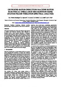
Fig. 1. The induction motor SML-EC. The symbols denote the following electromechanical quantities: Ψ1 - stator flux space vector, E•2(n), I•2(n), Ψ•2(n) – rotor electromotive force, current and flux space vectors respectively, related to the n-th two-terminal of the machine SML-EC, E•2(n)=j(ωx-ωr)Ψ•2(n), ωr - rotor electrical angular velocity, ωr=ppωm, ωm - rotor mechanical angular velocity, pp - number of pole • pairs; superscript denotes rotor quantities referring to the stator side (the remaining symbols are denoted in the text)
The analysis has been conducted for the four-pole induction motor of Sg 132S-4 type with a solid rotor manufactured from the magnetic material S235JR, that is, for a machine characterized by a significant skin effect occurring in the rotor solid conductive structure. The investigated IM rated parameters and the considered rotor dimensions are listed in the table 1. Table 1. Investigated induction motor rated parameters and considered rotor dimensions 400 V ∆ Rated line voltage 5.25 A Rated line current 50 Hz Rated frequency 1450 rpm Rated speed 114 mm Rotor width 133,3 mm Rotor diameter Thickness of the S235JR 42,65 mm material 0,35 mm Thickness of the air gap
During the experiment, the measurement of instantaneous values of rotor speed and stator voltages and currents has been carried out at the motor slip changing in
25
30
35
40
45
50
f 2 [Hz]
b)
0
arg{ L _ 1(2)} [deg]
(4)
the range of s=(0÷1) and at the specified frequency of stator supply voltages. Moreover, the measurement of instantaneous values of the investigated IM electromechanical quantities has been performed at the reduced supply voltage in relation to the motor rated voltage to keep the IM operating point on the linear region of the motor magnetisation characteristics. Consequently, the impact of magnetic saturation on machine magnetic circuit parameters has been eliminated and therefore not taken into account in the analysis. In the next stage, according to the presented methodology, the inductance frequency characteristic L1δ(ω2) of the tested IM has been determined (Fig. 2). The estimation of electromagnetic parameters R•2(n), L•2(n) of machine SML-EC particular two-terminals has been performed in line with the procedure described in [5] by means of the genetic algorithm in the Matlab-Simulink environment [18], while the magnetizing inductance has been determined in pursuance of the following relationship Lµ=L1δ(ω2=0).
L _ 1 (2) [H]
The representation of the rotor impedance Z2(ω2) occurring in the equation (3) by a sequence of parallelconnected two-terminals composed of R•2(n), L•2(n) elements (4) leads to an approximation of the actual IM inductance L1δ(ω2) frequency characteristic by means of the machine SML-EC (Fig. 1) [2]-[5]. In this way, the approximate representation of a machine with distributed parameters by an equivalent circuit with lumped parameters is achieved. The number N0 of parallel connected R•2(n), L•2(n) twoterminals of an approximated SML-EC results from required accuracy of the actual inductance frequency characteristic representation by the equivalent circuit in the considered frequency range [5]. Stator phase winding parameters R1, L1 are determined analytically or through measurement. The parameters R•2(k), L•2(k) and Lµ are subjected to an estimation process, which can be conveniently carried out using evolutionary algorithms.
Measurement SML-EC T-EC
-10 -20 -30 -40 -50 -55
0
5
10
15
20
25
30
35
40
45
50
f 2 [Hz]
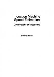
Fig. 2. The measured IM inductance frequency characteristic L1δ(ω2) and its approximation by the machine SML-EC: a) modulus; b) argument
A strong convergence between the investigated IM inductance L1δ(ω2) frequency characteristic calculated with the use of the machine SML-EC and the one determined on the basis of conducted measurement can be observed (Fig. 2). As demonstrated in [7], the characteristic unequivocally reproduces, in the motor considered operating range, the rotor electromagnetic parameters’ variability resulting from the skin effect occurring in rotor conductive elements, at any frequency of stator supply voltages. In view of the above, the mathematical model basing on the machine SML-EC has been used in electrodynamic state simulations of the tested IM variable-frequency speed control system. Based on specified IM state variables derived from these simulations, the operation reliability and accuracy of the proposed IM angular velocity and rotor flux space vector estimation algorithms have been verified. Estimation of IM angular velocity and rotor flux space vector In the study, simulations of selected operating conditions of the investigated IM variable-frequency drive with scalar control have been performed. The mathematical
PRZEGLĄD ELEKTROTECHNICZNY, ISSN 0033-2097, R. 91 NR 12/2015
241
model of the IM speed control system has been constructed with the assumption that the motor velocity measurement is available. It has also been established, that the mathematical model of an IM state variable estimator is supplied by signals derived from the scalar-controlled IM drive simulation model and operates in an open-loop system. Hence state variables being determined during an estimation process have not been used in the IM variablefrequency speed control system. The investigated IM angular velocity and rotor flux space vector have been subjected to the estimation process. The waveforms of these state variables have been determined, with the use of the scalar-controlled IM drive simulation model with the machine SML-EC, at predefined angular velocity changes (0.05ωN→ωN→0.5ωN→0.05ωN, ωN – rated angular velocity) and a constant load torque equal to the tested IM rated torque. Evaluation of operation accuracy of the considered state variables’ estimators has been made on the basis of the instantaneous relative errors (5) between the values of specified motor state variables derived from the scalar-controlled IM drive simulation model and the values of corresponding state variables determined through an estimation process. In addition, the root mean squared errors (6) of the examined state variables’ reconstruction have been calculated in the strictly defined time intervals resulting from the considered electromechanical transients. (5)
x i
x i x ie 100 % xi k
(6)
x
xi xie
L1
2
i 1
U 1
k 1
dΨ 2 L2 dI U R1 I 1 L1 1 dt Lμ 1 dt
R1
I 1
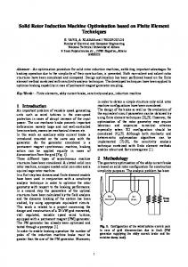
Mathematical model of the classical MRAS-type estimator In the classical MRAS-type estimator presented in [8], two independent simulators of the rotor flux space vector Ψ•2 (7) and (8) (expressed in the stationary reference frame ωx=0) are used. Since the quantity ωr is not involved in the equation (7), this simulator is regarded as a reference model of the rotor flux space vector Ψ•2, whereas the simulator (8), which does involve the rotor angular velocity, is regarded as an adjustable model. The output signals of the two models are compared with each other and an error between their states is supplied to the input of a suitable adaptation mechanism, which generates the angular velocity estimate ωre for the adjustable model (8) in accordance with the block diagram presented in figure 3 [8].
242
where: L1, L•2 – stator and rotor self-inductance, L1=L1+Lµ, L•2=L•2+Lµ, L•2 – rotor leakage inductance, σ – motor leakage coefficient, σ=1-Lµ2(L1L•2)-1, R•2 – rotor phase winding resistance, superscript e refers to estimated state variables. The mathematical model of the classical MRAS-type estimator is based on the IM T-type equivalent circuit (TEC) with constant parameters. In figure 2, the inductance L1δ(ω2) frequency characteristic calculated by means of the mathematical model founded on the machine T-EC with constant parameters has also been presented. The equivalent circuit parameters have been determined on the basis of instantaneous values of stator voltages and currents measured during the standard no-load and shortcircuit tests. The machine mathematical model of this type does not represent correctly the actual inductance L1δ(ω2) frequency characteristic of the tested IM, thereby the variability of rotor electromagnetic parameters resulting from the skin effect occurring in the rotor solid conductive structure. Therefore, the application of a mathematical model basing on the machine T-EC with constant parameters in a state variables’ estimation process of IMs with cage or solid rotors introduces greater reconstruction errors, a more intense skin effect occurs in rotor conductive elements. I 1
where: x, xe – instantaneous values of a specified state variable determined from the scalar-controlled IM drive simulation model with the machine SML-EC and an estimated one, respectively. For the purposes of comparison, the waveforms of the investigated IM angular velocity and rotor flux space vector magnitude obtained by the estimation process and also the instantaneous relative errors of these state variables’ reconstruction curried out by means of the classical MRAStype estimator [8] have been presented. In the estimator mathematical model, a three-level hysteresis regulator has been used.
(7)
dΨ 2e R2 Lμ I 1 Ψ 2e jωre Ψ 2e dt L2
(8)
L2 Lμ
Ψ 2
L1
U 1 I 1
R1
Lμ
L2 Regulator
R2
L2
L2 Lμ
Ψ 2
Ψ 2e
R2
ω re
L2 R2
I 1
Lμ
R2 L2
Ψ 2e
Fig. 3. The block diagram of the classical MRAS-type estimator [8]
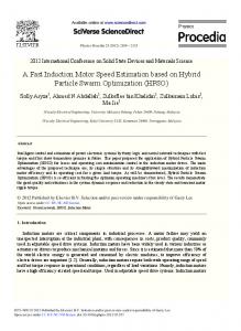
In figures 4 and 5, the waveforms of the tested IM angular velocity ωm and rotor flux space vector magnitude calculated by means of the scalar-controlled IM drive simulation model with the machine SML-EC are put together with the appropriate waveforms of these quantities, reconstructed with the use of the classical MRAS-type estimator. The motor state variables presented in the aforementioned and the subsequent figures are expressed in the per unit (pu) system. The base quantities are listed in the table 2 [17].
PRZEGLĄD ELEKTROTECHNICZNY, ISSN 0033-2097, R. 91 NR 12/2015
Table 2. Base quantities. The symbols U1Nph, I1Nph, f1N denote the following stator rated quantities: phase voltage, phase current and frequency respectively Ub=√2U1Nph Base phase voltage Ib=√2I1Nph Base phase current ωb=2πf1N Base angular frequency ωbm=ωb/pp Base angular velocity Sb=3/2UbIb Base power Tb=ppSb/ωb Base torque Ψb=Ub/ωb Base flux Lb=Ψb/Ib Base inductance Zb=Ub/Ib Base impedance
The instantaneous relative errors of the IM angular velocity Δω and rotor flux space vector magnitude ΔΨ estimation, determined according to the equation (5), can be observed in figure 6. In figure 7, the waveforms of the α – and β – axis components of the rotor flux space vector derived from the simulation model of the tested IM variablefrequency drive and the waveforms of this vector components estimated by means of the classical MRAStype estimator have been presented for the selected time interval.
Algorithmic methods for an IM electromechanical state variables’ estimation, which use mathematical models basing on the machine T-EC with constant parameters, are characterized by a certain sensitivity to the variability of motor electromagnetic parameters or their incorrect identification. In the case of the classical MRAS-type estimator, this sensitivity appears mostly in the low-speed range (5 percent of the tested IM rated velocity), then the instantaneous relative errors of considered state variables’ reconstruction are the highest. The literature proposes a number of MRAS-type estimator modifications [9]-[14], the use of which makes it possible to reduce the estimation process sensitivity to the variability or the incorrect identification of motor electromagnetic parameters, which in turn increases the reliability and accuracy of estimator operation. The neutralization of the influence of rotor electromagnetic parameters’ variability on the quality of an IM state variables’ estimation process is also obtained by simultaneous reconstruction of these parameters’ variability [15]-[16]. 1.4 1.0 0.6
m
0.8
m [pu]
2 [pu]
1
e
m
0.6 0.4
0.2 -0.2 -0.6
__ 2
-1.0
e __ 2
-1.4 1.8
1.9
2
2.1
2.2
2.3
2.4
2.5
2.6
2.7
2.8
t [s]
0.2 1.4 0
0
2
4
6
8
10
12
14
1.0
t [s]
1.4
0.2 -0.2 -0.6
__ 2
-1.0
e __ 2
-1.4 1.8
1 0.8
0
2
4
6
8
10
12
14
t [s] •e
2
rotor
50
0
40
-8
30
-16
20
-24
10
-32
0
0
2
4
6
8
10
12
[%]
•
[%]
2.1
2.2
2.3
•
e __ 2
Fig. 5. The waveforms of calculated Ψ 2 and estimated Ψ flux space vector magnitude
-10
2
2.4
2.5
2.6
Fig. 7. The waveforms of calculated Ψ 2 and estimated Ψ space vector components
__ 2
0.6 0.4
1.9
2.7
2.8
t [s]
__ 2 [pu]
1.2
0.6
2 [pu]
Fig. 4. The waveforms of calculated ωm and estimated ωem angular velocity
-40
-48 14
t [s]
Fig. 6. The waveforms of angular velocity ∆ω and rotor flux space vector magnitude ∆Ψ estimation relative errors
•e
2
rotor flux
Mathematical models of the estimators based on the machine inductance frequency characteristic The operation of the proposed algorithm for an IM angular velocity estimation is based on determining instantaneous values of the motor inductance L1δ(ω2,t), which are subsequently compared with the selected reference frequency characteristic of the IM inductance L1δ(ω2) (Fig. 2a or Fig. 2b) in order to estimate the frequency f2 of currents induced in rotor conductive elements. Examining the IM inductance variation as a function of the rotor current frequency (Fig. 2), it is worth noting that both the components of the characteristic L1δ(ω2), i.e. modulus and argument, are monotonic in the considered frequency range. Thus, the specified value of the inductance L1δ(ω2) modulus or argument corresponds to the specified frequency of currents induced in rotor conductive elements. Taking into account the above property of the analysed IM inductance frequency characteristic, a motor angular velocity estimation process can be carried out based on the selected component of the inductance L1δ(ω2). The stator inductance L1δ(ω2,t) instantaneous values are determined according to the relationship (3) with the use of electrical waveforms obtained from the scalar-controlled IM drive simulation model with the machine SML-EC. Basing
PRZEGLĄD ELEKTROTECHNICZNY, ISSN 0033-2097, R. 91 NR 12/2015
243
3
4
2
2
1
0
0
-2
-1
-4
-2
L2 res
n 1 L2 n
0
2
4
6
8
10
-5 14
12
1.2 0.8
The waveforms of the investigated IM angular velocity and rotor flux space vector magnitude derived from the scalar-controlled IM drive simulation model with the machine SML-EC and the corresponding waveforms of these quantities estimated in line with the above described methodology have been shown in figures 8 and 9. The instantaneous relative errors of these state variables’ reconstruction can be seen in figure 10.
0.4 0 -0.4
__ 2
-0.8 -1.2 1.8
e __ 2
1.9
2
2.1
2.2
2.3
2.4
2.5
2.6
2.7
2.8
t [s] 1.2
1
m
0.8
0.8
2 [pu]
e m
0.6 0.4
0.4 0 -0.4
__ 2
-0.8
0.2
0
2
4
6
8
10
12
14
t [s]
Fig. 8. The waveforms of calculated ωm and estimated ωem angular velocity 1.4 1.2
1 0.8 __ 2
0.6 0.4
-4
Fig. 10. The waveforms of angular velocity ∆ω and rotor flux space vector magnitude ∆Ψ estimation relative errors
I R j1 L1σ U 1 I 2e 1 1 f1 n 1 R j1 L2n 2 n f2
0
-3
-8
t [s]
N0
(12)
-6
-10
1
2 [pu]
N0
1
(11)
m [pu]
4
6
Ψ 2e Lμ I 1 Lμ L2res I 2e
(10)
__ 2 [pu]
5
8
2π f1 f 2 pp
The estimated rotor current frequency f2 together with the mathematical model resulting from the machine steadystate SML-EC can be used to estimate the rotor flux space vector Ψ•e2 in pursuance of the following formulas:
e __ 2
0
2
4
6
8
10
12
14
t [s] •
Fig. 9. The waveforms of calculated Ψ 2 and estimated Ψ flux space vector magnitude
•e
2
rotor
In figure 11, the waveforms of the α – and β – axis components of the rotor flux space vector obtained as a result of the conducted simulations of the tested IM variable-frequency drive operation and the waveforms of this vector components estimated by means of the proposed algorithms have been presented for the same time interval as in figure 7. The root mean squared errors of the IM angular velocity σω and rotor flux space vector magnitude σΨ estimation,
244
10
[%]
me
(9)
determined according to equation (6) in strictly defined time intervals, are put together in the Table 3.
[%]
on the knowledge of estimated rotor current frequencies f2 and these of stator supply voltages f1, the motor angular velocity is reconstructed according to the following equation [7]:
-1.2 1.8
e __ 2
1.9
2
2.1
2.2
2.3
2.4
2.5
2.6
2.7
2.8
t [s] •
Fig. 11. The waveforms of calculated Ψ 2 and estimated Ψ flux space vector components
•e
2
rotor
Table 3. Root mean squared errors of the investigated IM angular velocity and rotor flux space vector magnitude estimation 2≤t