Round Reduction Using Faults Hamid Choukri1 and Michael Tunstall1,2 1
2
Gemplus Card International, Applied Research & Security Centre, Avenue des Jujubiers, La Ciotat, F-13705, France.
[email protected],
[email protected] Royal Holloway, University of London, Information Security Group, Egham, Surrey TW20 0EX, UK.
[email protected]
Abstract. This paper presents a practical implementation of a fault attack implemented on a Silvercard (a freely available smart card based on a PIC16F877 produced by Microchip). The aim of the fault attack is to effectively reduce the number of rounds of a secret key algorithm. The simplest case of reducing the number of rounds to one was chosen to facilitate subsequent cryptanalysis. The fault injection method used is a glitch on the power supplied to the smart card. The manner in which this changes the functioning of the smart card is described, followed by how this effect can then be used to produce the desired result. A description of how this was applied to an AES implementation is given. Lastly, Various generic countermeasures are discussed to show how this type of attack can be prevented.
1
Introduction
Secret key cryptographic algorithms such as DES and AES are based on a function that is computed iteratively as a series of rounds to provide a high level of security. This function is referred to as the round function. In [2] the idea was put forward to implement a fault attack that would effectively reduce the number of rounds of a secret key cryptographic algorithm to enable the key to be derived. In this paper an attack on AES is demonstrated which effectively reduces the number of rounds of an AES to one. The cryptanalysis of the resulting algorithm is simple and only requires two plaintext/ciphertexts pairs. The method used to characterise the fault injection technique and then how such an attack can be achieved in practice. A transient glitch is used that produces a provisional fault within the chip. The actual effect of the fault within the chip cannot be described accurately without reverse engineering the chip, but some hypotheses are proposed as to what impact the fault may have. It should be noted that the Silvercard contains no sensors that test the smart cards environment. This is a standard feature of all modern smart cards and are designed to thwart fault attacks such as that presented in this paper. The research was more oriented towards the possible effects of fault injection and fault analysis rather than the possible effects on actual smart cards.
The AES algorithm implementation used is a naive one, in the sense that no countermeasures are present against any sort of attack. The implementation will be vulnerable to power analysis and other forms of fault attacks. The aim being to show that precise faults can be induced within a chip that can lead to theoretically simple attacks.
2
Fault Injection
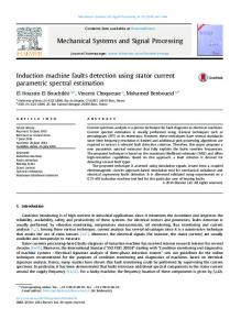
There are various different ways in which a fault can be induced in a microcontroller. These include methods such as a particle accelerator [3], a laser [8] or light [10]. These types of fault injection need the chip to be decapsulated so that the surface of the chip can be accessed. A simpler method of fault injection is to insert a glitch on the power supply pin, so that the processor misinterprets an instruction or a variable. A description of the different types of glitches that can be applicable to a microcontroller can be found in [1]. Figure 1 represents a SPICE (a general-purpose circuit simulation program [12]) simulation of an inverter’s response to a transient variation on the power supply voltage. The goal is to give an example of a glitch’s effect on the chip. An inverter was chosen as this is the basic building block from which logical gates can be created. When the inverter output is set to 0 the glitch has no noticeable effect. However, when the output is switched to 1 the glitch changes the output value quite considerably. This shows that a glitch will produce an effect within the chip but unfortunately we cannot predict exactly what this will be. Similar effects can be produced using a laser [6]. In order to find a glitch that would have this type of impact on a smart card, an implementation of AES was used as a way of detecting a glitch. Numerous different glitch configurations were applied to AES, with no effort made to produce any particular effect. Every time an erroneous result was produced, the configuration that produced that result was recorded. The external clock speed was varied between 1 MHz and 5 MHz in steps of 1 MHz. The size of the glitch varied between 1 clock cycle and 10 clock cycles in steps of 1 clock cycle. The applied voltage started at 3 volts and was incremented in steps of 0.5 volts to 5 volts. All the possible combinations of these three parameters were tested at 200 different positions in the computation of an AES. The voltage applied during the glitch was determined by dichotomy by finding the voltage limit at which the smart card did not respond correctly. The boundaries set for the dichotomy were between 0.25 volts and the voltage applied during the normal functioning of the smart card. The corrupt responses were used to determine the different glitch configurations that succeeded in inducing a fault. Various different configurations that worked with an external clock set to 5 MHz. The smallest glitch size that created a fault was chosen to give as much precision as possible when an attempt is made to use this in a fault attack. In this implementation this was one clock cycle. The voltage applied to the card was chosen arbitrarily amongst those configurations
Fig. 1. The upper image shows the response of the inverter to a glitch when its output should be 0. The lower image shows the response when the output should be 1. In each case, a glitch has been applied to the supply voltage of the inverter. The effect can clearly be seen in the lower image.
that worked. The voltage level of the glitch itself was not deemed to have any importance, as it was assumed to be variable given the chip’s behaviour would change as it heats up. This process took approximately 24 hours.
3
The Fault Target
The model used to try and imagine the effect of a fault during the execution of AES was that of a fault producing a change in the code executed, as described in [1]. For this reason the code executed was examined to determine where a fault could be injected. In general, the implementation of a secret key cryptographic algorithm in the PIC assembly language will have the following format. movlw movwf RoundLabel
0Ah RoundCounter
call
RoundFunction
decfsz goto
RoundCounter RoundLabel
The RAM variable (RoundCounter) is set to the number of rounds required, which for the example that is described in this paper (AES) the value loaded into the counter is 0A in hexadecimal. The round function is executed, which has been represented by a call to the function RoundFunction. The RoundCounter variable is then decremented, and the round is repeated until RoundCounter is equal to zero, at which point the loop exits. It is this loop that we are trying to change so that it exits earlier than expected. The target of the fault is the decfsz step, which consists of a decrement, a test, followed by a conditional jump. The conditional jump is present as jump of one instruction when the test is positive; otherwise the next instruction is executed. The aim of the attack is to reduce the algorithm to one round. It is not possible to remove the first round entirely as the first conditional test is after the first round. The instruction can be broken down into three different tasks, the first being the decrementation: Decrement task: RoundCounter