Sep 3, 2012 - that contain both wired networks and wireless mesh networks. Routing is ... internetwork as a whole brings several advantages. In this realm ...
Routing Across Wired and Wireless Mesh Networks: Experimental Compound Internetworking with OSPF Juan Antonio Cordero Fuertes, Matthias Philipp, Emmanuel Baccelli
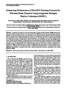
Abstract— As wireless mesh networks are deployed, a new concept emerges: compound internetworks, i.e., internetworks that contain both wired networks and wireless mesh networks. Routing is one of the key challenges that arises in compound internetworks: indeed, while specific routing protocols are typically used for wired networks on one hand, and for wireless mesh networks on the other hand, it has been observed that operating a single routing protocol to manage a compound internetwork as a whole brings several advantages. In this realm, the IETF has thus standardized protocol extensions to Open Shortest Path First (OSPF, the routing protocol used by more than 50 % of the wired routers in today’s Internet), enabling OSPF to operate simultaneously on wired networks, and on wireless mesh or moderately mobile ad hoc networks (MANETs). This paper evaluates the performance of OSPF coupled with such a protocol extension for MANETs on an experimental compound internetwork testbed. This paper reports on experiments carried out with OSPF operating simultaneously over Ethernet and 802.11b. Despite the limitations of the testbed, these experiments provide both a proof-of-concept and complementary results compared to prior work in the domain, which was mostly based on simulations, and focused on wireless ad hoc network scenarios only.
I. I NTRODUCTION The advent of packet radio networks and lead to new concepts such as Mobile Ad hoc Networks (MANETs) or wireless mesh networks. Since the late 1990’s, several research efforts have focused on enabling communication in such wireless multi-hop networks in which topology is spontaneous and dynamic. This resulted in different routing protocols being designed for wireless mesh networks and MANET operation, the most prominent to date being OLSR [13] and AODV [15]. OLSR is for instance deployed in many urban wireless community mesh networks around the world [21]. In practice, the interconnection of wired networks with wireless mesh networks in the Internet gives birth to Autonomous Systems (AS) containing both mesh and fixed networks – such an AS is hereafter denominated compound AS. An approach for routing in a compound AS consists in splitting the AS into several routing domains, and then to use a separate routing protocol for each domain: on one hand MANET-specific protocols in wireless mesh networks, and on the other hand, routing protocols designed for wired networks. An alternative approach consists in using a single routing protocol for the whole compound AS. The former approach requires the presence in the AS of routers with specific hardware and software capabilities, denominated gateways, in order to provide connectivity between different routing domains. The latter approach, explored in this paper,
reduces the cost of network maintenance and operation as no such gateways are needed [2], and naturally avoids bottlenecks created by such gateways. This is, however, at the expense of increasing the complexity of the employed routing protocol, which thus needs to handle the diverse characteristics of wireless mesh and wired networks with the same core mechanisms. In today’s Internet, IGP routing [16] is essentially provided by two protocols based on the link state algorithm : OSPF [17] [10], and ISIS [18]. This paper explores the use of OSPF to provide routing in compound ASes, and evaluates its performance on a compound internetwork testbed. A. Related Work Leveraging the commonality between OLSR and OSPF (both based on the link state algorithm), operation of OSPF on MANETs has recently been considered. This approach may indeed be cost-effective concerning the integrating of wireless mesh networks in existing infrastructure, as more than 50% of routers in the Internet already run OSPF. Early studies and proposals such as [14] [19] paved the way to IETF standardizing several OSPF protocol extensions for operation over ad hoc networks [9] [6] [8]. Various studies have evaluated and compared the performance of these extensions in mobile ad hoc scenarios [7], [12], [20], essentially via simulations. Further improvements of these extensions have been proposed in [3], [4], still comparatively evaluated via simulations in MANET only scenarios. In contrast, this paper evaluates OSPF on a real testbed that consists of a wireless mesh network interconnected with a fixed wired network. II. T HE OSPF P ROTOCOL AND ITS MANET E XTENSION OSPF [10], [17] is a link-state routing protocol for IP networks. This implies that each router maintains a local instance of the Link-State Database (LSDB), representing the full network topology – with the objective of the protocol being that each router should have the same information in its local instance of LSDB and, thus, the exact same view of the network topology. Paths to every possible destination are derived from the Shortest Path Tree (SPT) that every router computes, by way of Dijkstra’s algorithm. Although OSPF supports network partitioning in several routing areas, the work described in this paper explores the use of a single area for routing in the whole internetwork. Routers acquire local topology information and advertise their own presence by periodically exchanging Hello messages with all their 1-hop neighbors (i.e., neighbor sensing).
With such signaling, each router becomes aware of its immediate network topology, i.e. its 2-hop neighborhood. This also allows verification of bidirectional connectivity with 1-hop neighbors (then called bidirectional neighbors). Each router also explicitly synchronizes its local instance of LSDB with a subset of its bidirectional neighbors. Links between a router and its synchronized neighbors are called adjacencies, and are required to form a network-wide connected backbone, connecting all routers in the network, in order to ensure paths can be computed correctly. Finally, routers also acquire remote topology information by way of receiving Link State Advertisements (LSA). Each such LSA lists mainly the current adjacencies of the router which generated the LSA. LSAs are disseminated through the entire network in reliable fashion (explicit acknowledgements and retransmissions) via the backbone formed by adjacencies; this operation is called LSA Flooding. Thus, any router which has formed adjacencies must advertise this periodically by way of originating an LSA and performing LSA flooding. Remote topology information is then used for the construction of the Shortest Path Tree: each router computes the shortest paths over the network graph described in the set of received LSAs it, by way of Dijkstra’s algorithm. A. Packet Types Routers in OSPF use five types of messages and packets to exchange topology information over the networks, some of them have been already mentioned in this section: Hello packets are used for neighbor sensing, Database Description (DBDesc) packets are exchanged for LSDB synchronization and Link State Advertisements (LSAs) are used for topology reliable flooding and update. After the exchange of DBDesc packets, a router in process of LSDB synchronization may request to its synchronizing neighbor the retransmission of particular LSAs – these requests are sent by way of Link State Request (LSReq) packets. Several LSAs may be sent in a single Link State Update packet (LSU). Several LSA acknowledgements may also be grouped in a single Link State Acknowledgment (LSAck) packet. B. Interface Types for Wired Links Rules for flooding and adjacency handling vary for the different interface types supported by OSPF. In broadcast and non-broadcast multiple access (NBMA) interfaces, the flooding procedure is mainly managed by Designated Routers (DRs). A Designated Router is elected among routers whose interfaces are connected to the same link. Such a DR forms adjacencies with all the routers connected to the same link, and it becomes responsible for flooding of LSAs, originated by routers on that link. In point-to-point and pointto-multipoint interfaces, all links are synchronized and all interfaces participate in LSA flooding. C. MANET Interface Type The MANET interface type is defined in the extension of OSPF for operation over MANETs. Three different extensions have been standardized by the IETF [6], [8], [9],
each of which specifies mechanisms to optimize topology description, flooding and LSDB synchronization in wireless ad hoc environments. The experiments carried out used RFC 5449 [9]. Wireless interfaces following this specification select a set of MultiPoint Relays (MPRs) among its bidirectional neighbors [13]. The set of MPRs selected by the wireless interface of a router must ensure that every packet received from the router reach all 2-hop neighbors of the selecting interface in 2 hops (MPR coverage criterion). A link between a router and one of its MPRs is denominated MPR link. LSA flooding is then performed through MPRs, meaning that an LSA transmitted (originated or forwarded) by an interface is retransmitted by the MPRs of such interface. Links between interfaces and their MPRs are synchronized and thus become adjacent. Moreover, each interface describes in its LSAs the set of MPRs and MPR selectors. As the set of adjacencies based on MPR selection may not provide a connected subgraph, links from one additional router in the network (denominated synch router) are also declared adjacent to ensure adjacency set connection [5]. The Shortest Path Tree is then constructed over the set of adjacencies. III. T ESTBED D ESCRIPTION This section describes the characteristics of the employed networking testbed. Section III-A presents the distribution of computers in the testbed and the network topology that they form. Section III-B details the implications of such topology in OSPF routing. A. Interfaces Configuration and Network Topology The testbed is composed of 6 fixed computers (routers/hosts) attached to two interconnected networks: a wired network and a wireless network. Table I indicates the network interfaces of each computer. For more details about computers’ hardware, see the Appendix. Computer server hybrid1 hybrid2 wless1 wless2 wless3
Abbr. S h1 h2 w1 w2 w3
Wired ifs. eth1, eth2 eth1 eth1 – – –
Wireless ifs. – wlan0 wlan0 wlan0 wlan0 wlan0
TABLE I N ETWORK INTERFACES OF TESTBED COMPUTERS .
1) Physical Topology: The internetwork connecting these computers was deployed in the Computer Science Lab (Lab´ oratoire d’Informatique, LIX) of Ecole Polytechnique, in Paris (France). Three scenarios –I, II and III– were configured over the resulting internetwork. These scenarios permit to test the communication between computers wless3 and server, for different situations. The physical distribution of computers at LIX is displayed in Figure 1. Positions of computers do not change, except for the case of wless3, which has a different position for scenario I and for scenarios II and III, as shown in Figure 1.
Interface hybrid1:wlan0 hybrid2:wlan0 wless1:wlan0 wless2:wlan0 wless3:wlan0
(II, III)
w3
h1 S h2
(I)
w2
w1 w3 10 m
Fig. 1.
II w1 w2 w2 w1 w1
III – w2 w2 w1 w1
TABLE II MPR S SELECTED BY EACH WIRELESS INTERFACE , FOR EACH SCENARIO .
Computers position over the plan of LIX.
2) Logical Internetwork Topology: Each scenario corresponds to a specific internetwork topology. Figure 2 indicates the internetwork topology graphs for scenarios I, II and III. In the wired network, computers communicate through the IEEE 802.3 (Ethernet) standard protocol, server is connected with hybrid1 by way of interface eth1 and with hybrid2 by way of interface eth2, as shown in Figure 2. In the wireless network, interfaces communicate through the IEEE 802.11b WLAN standard protocol, and all wireless routers (hybrid1, hybrid2, wless1, wless2 and wless3) use their wireless interface wlan0. The topology that results from wireless reachability among computers hybrid1, hybrid2, wless1, wless2 and wless3 is modified by means of MAC filtering in order to disable links h1 ←→ h2 , w1,3 ←→ w2 , w1,3 ←→ h2 and w2 ←→ h1 . In scenario III, link h1 ←→ w1 is suppressed by disabling interface wlan0 at computer hybrid1. eth1 S eth2
eth1 S eth2
eth1 S eth2
eth1
eth1
eth1
eth1
eth1
h1
h2
h1
h2
h1
wlan0
wlan0
wlan0
w3 wlan0
h2 wlan0 wlan0
wlan0
w1
w2
w3 wlan0
I
eth1
wlan0
wlan0 wlan0 w2
Fig. 2.
I w1 w2 – w3 w2
wlan0
w1
w2
w3 wlan0
II
III
Considered topologies for scenarios I, II and III.
B. OSPF Routing Configuration All interfaces use the extended OSPFv3 routing protocol, wired and wireless interfaces using different interface types. Wired interfaces are configured as point-to-point interfaces, as specified in RFCs 2328 [17] and 5340 [10]. Wireless interfaces are configured as MANET interfaces, as specified in the MPR-OSPF MANET extension (RFC 5449 [9]). 1) OSPF Adjacencies and MPRs: According to the specification of OSPF and MPR-OSPF extension, all links in any of the considered topologies for scenarios I, II and III are adjacent. Within the wired network, every point-to-point link is an adjacency. In the wireless network, wireless links are adjacent if they are MPR links. The list of MPRs of every wireless interface, for each scenario, is displayed in Table II. It can be observed that all links are MPR links, and therefore all are adjacent. In this topology, the presence of a
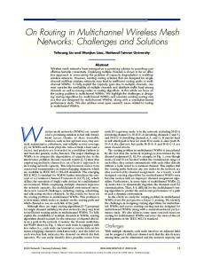
synch router (see section II-C) is thus redundant. 2) OSPF Flooding: Flooding in the wired network is performed through adjacent links, i.e. S ←→ h1 and S ←→ h2 . In the wireless network, flooding is performed: • through the MPR links (from a wireless router towards its MPR), and • through all links connecting an interface to a hybrid router (hybrid1 and hybrid2). IV. E XPERIMENTS AND R ESULTS For each scenario (I, II and III), communication between wless3 and server is tested by way of two experiments: • Transmission of ICMPv6 [11] requests (pings) from wless3 to server. The measure of time between the transmission of an ICMP request and its reply corresponds to the Round Trip Time (RTT) of the ping through the evaluated path. • Transmission of a constant bit rate data UDP flow from wless3 to server. Comparison between packets sent and packets received permits to test the quality of the traversed paths and the wireless links that compose them in each scenario. For a detailed description of these UDP flows, see Table III in the Appendix. Displayed results in this section show the most prominent averaged measurement values over tens of samples (see the Appendix for details); a complete description of the obtained results can be found in [1]. The three considered scenarios (I, II and III) are complemented by another scenario in which information is transmitted and measured through the wired link h1 ←→ S. Results on this scenario are added for completeness. Section IV-A presents the results obtained in both experiments, for each scenario, in terms of quality of wireless links. Section IV-B examines the amount and structure of OSPF control traffic. A. Wireless Mesh Communication Figures 3.a and 3.b display the results of the performed experiments, in particular the delay for ICMP requests (pings) and the packet delivery ratio of CBR UDP data flows. Figures 3.a and 3.b indicate the degradation of the quality of communication between routers wless3 and server as the number of wireless links between them increases. As expected, the wired link h1 ←→ S has an almostideal behavior: 100% PDR and no significant delay. The negative impact of wireless links in the path from source to destination is close-to-linear with the number of traversed
With 95% confidence interval
1.2
use wired links than wireless links, whenever possible, even if it means more hops in the end. This observation confirms that metrics used should indeed be able to track link quality, and that OSPF sepcifications such as [9] [6] [8] should be completed with a standard way to do that in MANETs.
1.0
PDR
0.8 0.6
B. OSPF Control Traffic Pattern
0.4 0.2 0.0
900
0
1 2 Number of wireless hops
700
(a) Packet Delivery Ratio (PDR)
600
With 95% confidence interval Bytes
60
LS-Request LS-Update LS-Ack Hello Database Description
800
3
50
500 400 300
40 ms
200
30
100 0 0
20
50
100
150 200 Seconds
250
300
10
Fig. 4. 0
0
1 2 Number of wireless hops
3
(b) Round Trip Time (RTT) Fig. 3. PDR of UDP flows and RTT of ICMP requests, depending on the number of wless hops.
wireless links, as shown in Figure 3.a: more than 30% of transmitted packets are lost in the first wireless link, and such percentage increases about a 15% per additional wireless link included in the path. Figure 3.b shows that such degradation is also evident in terms of round trip time (RTT). Replies to ICMP requests are immediately delivered through a wired link, but the average and the variation of delays grow with the number of wireless links involved – is in the order of tens of miliseconds for 2 and 3 wireless links. While the impact on communication due to the use of wireless links depends on the specific topology and the network technology that is used, two conclusions can be drawn from these experimental results. As each additional wireless hop in the route of data packets in the network implies a significant degradation of the quality of communication, routing in wireless networks should preserve the principle of shortest (wireless) paths, meaning that the number of wireless links traversed by data packets should be minimized. This confirms the conclusions of simulationbased studies such as [20] which highlights the importance of not sacrificing path optimality for less control traffic. Moreover, in the context of compound internetworks with both wired and wireless links, it is obvious that ’optimal’ does not necessarily mean ’the least number of hops’, as implicitly used in previous work such as [7], [12], [3], [4]. Indeed, in compound internetworks, it is better for a path to
Control traffic overhead at server:eth1.
Figures 4, 5 and 6 display the evolution of OSPF control traffic transmitted by wireless interfaces wless3:wlan0 and hybrid1:wlan0, on one side, and the wired interface server:eth1, on the other. The five packet formats used in OSPF (Hello, LSUpdate, LSRequest, LSAck and DBDesc, see section II-A) can be distinguished in these figures. Measurements were taken with the topology of scenario I, each point indicating the number of bytes sent within an interval of 5 seconds. The traffic load of the internetwork was composed of a CBR UDP data traffic flow from wless3 towards server (see Table III), and OSPF control traffic. The figures show the structure of such control traffic, in terms of number of bytes, during the first 335 seconds of network operation, i.e., after routers’ startup. All interfaces are configured with the same OSPF parameters (see Table IV), in order to facilitate the comparison between control traffic patterns of each of them. 1) Hello Packets: The amount of Hello packets sent by each interface is kept constant along the monitored time. As HelloInterval = 2sec, interfaces transmit 2.5 Hello packets per interval of 5 seconds. The length of an average Hello packet is significantly longer in wireless interfaces (Figures 5 and 6) than in wired interfaces (Figure 4). For the same number of neighbors, Hellos from server:eth1 have 40 bytes while those from hybrid1:wlan0 have 75.34 bytes (average values). This is due to the fact that Hello packet format in RFC 5449 [9] includes additional information about link costs, adjacencies and MPR selection, which is added to the format specified in OSPF [17] and OSPFv3 [10]. 2) LSDB Synchronization: The existence of ongoing LSDB synchronization processes during the monitored time interval can be noticed in the OSPF control traffic structure
900
LS-Request LS-Update LS-Ack Hello Database Description
800 700
Bytes
600 500 400 300 200 100 0 0
Fig. 5.
50
100
150 Seconds
200
250
300
Control traffic overhead at wless3:wlan0.
by way of the presence of Database Description (DBDesc) packets. The fact that these packets are only present, for wired interfaces, in the first part of the monitored interval (from t = 0sec to t = 10sec, as shown in Figure 4 indicates that links become synchronized only when the routers are switched on. In contrast, DBDesc are transmitted in the whole monitored interval for wireless interfaces. This is consistent with the fact that wired links are mostly stable and therefore there is no need to repeat synchronization process after the first LSDB exchange. Wireless links, in contrast, are more prone to packet losses and link failures, and need thus to be synchronized several times during the network lifetime, even in the absence of router mobility. The same phenomenon can be observed with LSRequest packets, which can only be sent during the last phase of the LSDB synchronization process, when the synchronizing neighbors have completed the exchange of DBDesc packets. These observations are also consistent with simulation-based studies such as [20] which have studied the impact of link quality on OSPF control traffic.
900
LS-Request LS-Update LS-Ack Hello Database Description
800 700
Bytes
600 500 400 300 200 100 0 0
Fig. 6.
50
100
150 200 Seconds
250
300
Control traffic overhead at hybrid1:wlan0.
3) Link State Updates, Requests and Acknowledgements: LSUpdate packets contain one or more Link State Advertise-
ments (LSAs). Such LSAs can be either originated by the sending interface, either originated by another interface and flooded (forwarded) by the sending interface. Transmission of LSUpdate packets follows a common pattern in all the interfaces in the internetwork. Thus, pattern consists of periodic peaks followed by time intervals (valleys) in which the number and size of LSUpdate transmissions is lower and roughly constant. Despite the common pattern in the LSUpdate traffic, several differences can be observed between wired and wireless interfaces. This section concentrates on three particular aspects: peak width, height of valleys between consecutive peaks and transient state (after routers are switched on). a) Transient state: Immediately after switching on, wireless interfaces transmit a high number of packets – mostly, LSUpdate packets sent in response to LSRequest packets received during the first LSDB synchronization processes in all wireless links (Figures 6 and 5, between t = 0sec and t = 50sec). This amount of transmissions involves traffic rates above 220Bps (1.1kB per interval of 5sec), then decreases and stabilizes in a slightly lower level (maximum peak of 130Bps). The opposite behavior is found in wired interfaces (Figure 4), in which the initial transient period of low LSUpdate traffic rate (about 26Bps = 130B 5sec for server:eth1) is followed by a steady period in which the minimum LSUpdate rate is slightly higher (about 29Bps = 145B 5sec for server:eth1). These different behaviors can be explained by the different roles that flooding has over wired and wireless links. Due to their stability, packets sent over wired links are mostly forwarded packets – that is, they come from other interfaces than those involved in the links. In the first instants in which there is no flooding over the network because adjacencies have not been formed in the network and flooding links have not yet been identified, the overall traffic traversing such wired links is temporarily low. The opposite is observed in wireless links. b) Peak width: Peaks are narrower in wired interfaces (∼ 10sec for server:eth1) than in wireless interfaces (∼ 25sec for hybrid1:wlan0, ∼ 30sec for wless3:wlan0). For interfaces attached to wireless links, there is a high probability that a topology change causes a new topology update before the LSRef resh interval – therefore, intervals between consecutive transmission of interfaces’ topology descriptions are shorter than LSRef resh and the width of the peak increases. In stable wired links, in contrast, intervals between consecutive transmissions are closer to the LSRef resh parameter and, therefore, LSUpdate transmission events are less spread in time. c) Depth of valleys: Besides the peaks caused by transmission of its own topology description, either periodic or as a reaction to a topology change, two other events may lead an interface to transmit LSAs: (i) forwarding of LSAs originated by other interfaces in the internetwork, and (ii) retransmission of LSAs not acknowledged by their intended destinations. Both additional events explain the presence of valleys with significant traffic rate, i.e., a non-zero minimum level of LSUpdate transmissions in the monitored interfaces. In wired (reliable) links such as server:eth1, such trans-
missions are caused by flooding, and involve about 25Bps (127B per interval of 5sec). Wireless interfaces such as wless3:wlan0 have a minimum LSUpdate transmission rate of about 16Bps (80B per interval of 5sec) caused by LSA retransmissions and flooding.
•
•
V. C ONCLUSION This paper addresses routing with OSPF across compound Autonomous Systems, i.e., internetworks combining wired networks and wireless mesh networks. Compound internetworks are bound to become a common phenomenon as wireless mesh networks are being deployed and coexist with wired networks. This paper reports on experiments carried out on a compound internetwork testbed confirm prior simulation-based studies analyzing OSPF control traffic over wireless links. We observed that even without mobility and a small number of wireless neighbors, link synchronization involves a continuous and substantial amount of traffic. This observation confirms that reducing the number of synchronized links is a priority when using OSPF over ad hoc networks. Furthermore, data path quality was observed to significantly decrease with each additional wireless hop involved in the path. This observation suggests that wired links should be preferred to wireless links whenever possible, and highlights the need to complement current OSPF specifications with a standard way to track link quality in compound internetworks. The importance of leveraging every possible wired connection indicates that all links in the compound AS should be taking into consideration for route computation. As this implies a large number of gateways between routing domains when several routing protocols are used in the AS, and this is costly, a single routing protocol is prefered in order to avoid gateways.
Name Value HelloInterval 2 sec DeadInterval 10 sec RxmtInterval 5 sec AckInterval 2 sec MinLSInterval 5 sec MinLSArrival 1 sec LSRefreshInterval 60 sec TABLE IV OSPF PARAMETERS .
R EFERENCES [1] [2]
[3] [4] [5] [6] [7] [8]
A PPENDIX •
•
•
Testbed Hardware – Wired interfaces: DECchip 21140. – Wireless interfaces: Broadcom BCM4306 WLAN. Testbed Software – Operating System: Ubuntu v.10.04 with kernel 2.6.32. – Routing Protocol Implementation: ospf6d daemon of Quagga/Zebra routing suite v.0.99.15. ∗ Wired interfaces: Point-to-point. ∗ Wireless interfaces: MANET (RFC 5449 [9]). Setup for PDR and RTT Measurements – Routers were switched on within [0, 2]sec. – PDR results averaged over 84 iterations. – ospf6d daemon NOT restarted in each iteration. – UDP flows, started 60sec after ospf6d daemon switchon: Nominal sender bit rate Packet payload CBR real traffic rate Flow duration
100 pkts/s 1024 bytes ∼ 300 kbps 5 min/flow
TABLE III
[9] [10] [11] [12] [13] [14] [15] [16] [17] [18] [19] [20]
C HARACTERISTICS OF TRANSMITTED UDP FLOWS . [21]
– RTT results averaged over 60 iterations.
– ICMPv6 requests did not overlap with UDP flows. Setup for Control Traffic Measurements – Routers were switched within [0, 2]sec. – Results averaged over 84 iterations. – ospf6d daemon restarted in each iteration. – UDP flows: see Table III. OSPF Parameters: see Table IV.
Cordero, J. A.; Philipp, M.; Baccelli, E. (2011). Compound Wired/Wireless Internetworking with OSPF, Research Report # 7642, INRIA, Jun. 2011. Cordero, J. A.; Baccelli, E.; Clausen, T.; Jacquet, P. (2011). Wired/Wireless Compound Networking. In: Wang, X. (Ed.). Mobile Ad-Hoc Networks: Applications, InTech Publishers, ISBN 978-953307-416-0. Cordero, J. A.; Clausen, T.; Baccelli, E. (2011). MPR+SP – Towards a Unified MPR-based MANET Extension for OSPF. Proc. HICSS’44, Hawaii (US). Baccelli, E.; Cordero, J. A.; Jacquet, P. (2010). Optimization of Critical Data Synchronization via Link Overlay RNG in Mobile Ad Hoc Networks. Proc. MASS’44, San Francisco (US). Cordero, J. A. (2010). MPR-based Pruning Techniques for Shortest Path Tree Computation. Proc. 18th SoftCOM, Split (Croatia). Roy, A.; Chandra, M. (2010). RFC 5820, Extensions to OSPF to Support Mobile Ad Hoc Networking, IETF, Mar. 2010. Baccelli, E.; Cordero, J. A.; Jacquet, P. (2009). MPR Techniques with OSPF on Ad Hoc Networks. Proc. 4th ICSNC, Porto (Portugal). Ogier, R.; Spagnolo, P. (2009). RFC 5614, Mobile Ad Hoc Network (MANET) Extension of OSPF Using Connected Dominating Set (CDS) Flooding, IETF, Aug. 2009. Baccelli, E.; Jacquet, P.; Nguyen, D.; Clausen, T. (2009). RFC 5449, OSPF Multipoint Relay (MPR) Extension for Ad Hoc Networks, IETF, Feb. 2009. Coltun, R.; Ferguson, D.; Moy, J. (2008). RFC 5340, OSPF for IPv6, IETF, Jul. 2008. Conta, A.; Deering, S.; Gupta, M. (2006). RFC 4443, Internet Control Message Protocol (ICMPv6) for the Internet Protocol Version 6 (IPv6) Specification, IETF, Mar. 2006. Henderson, T.; Spagnolo, P.; Pei, G. (2005). Evaluation of OSPF MANET Extensions, Tech.Report D950-10897-1, Boeing, Jul. 2005. Clausen, T.; Jacquet, P. (2003). RFC 3626, Optimized Link State Routing Protocol (OLSR), IETF, Oct. 2003. Henderson, T. et al. (2003). A Wireless Interface Type for OSPF, Proc. MILCOM’03, pp. 137-145, IEEE ComSoc, Boston (US). Perkins, C.; Belding-Royer, E.; Das, S. (2003). RFC 3561, Ad hoc On-Demand Distance Vector (AODV) Routing, IETF, Jul. 2003. Halabi, S.; McPherson, D. (2000). Internet Routing Architectures, 2nd Edition, Cisco Press, ISBN 1-57870-233-X. Moy, J. (1998). RFC 2328, OSPF Version 2, IETF, Apr. 1998. Oran, D. (1990). RFC 1142, OSI IS-IS Intra-domain Routing Protocol, IETF, Feb. 1990. F. Baker et al. (2003). Problem Statement for OSPF Extensions for Mobile Ad Hoc Routing, IETF Internet Draft, Sept. 2003. Baccelli, E.; Cordero, J. A.; Jacquet, P. (2010). OSPF over MultiHop Ad Hoc Wireless Communications, In: IJCNC, Vol.2, No.5, Sept. 2010. Urban Wireless Community Mesh Networks: Freifunk Berlin www.freifunk.net, GUIFI Barcelona www.guifi.net, OPEN AIR Boston www.openairboston.net