Hariom Agrawal et al./ International Journal of Computer Science & Engineering Technology (IJCSET)
Routing protocols in underground coalmine environment: A Review Hariom Agrawal M.E. student, CSED Thapar University Patiala, India
[email protected]
Dr. A. K. Verma Associate Professor, CSED Thapar University Patiala, India
[email protected] Abstract- Researchers have worked on routing issues for adhoc-networks, VANET’s, and Wireless Sensor Networks in a normal scenario; recently there has been a recent trend towards the study on underground wireless networks and proposals for design and development for Wireless Underground Sensor Networks. This paper highlights the concept of wireless underground sensor network in the coal mine environment, its application and various protocols related to underground coal mine environment have been studied. The focus is on various issues, routing protocols and parameters used for comparison of their performance with an insight into the applications of underground wireless sensor network. No doubt, the WUSN has its own share of challenges and the research has just started. Keywords: Wireless Underground Sensor Networks; coal mine environment monitoring; Routing Protocols.
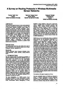
I. Introduction This work focuses on the concept of a Wireless Underground Sensor Network (WUSN). WUSNs can be used to monitor the underground environment, such as soil properties and mineral density for agricultural applications and toxic substances for environmental monitoring. Current technology to monitoring underground conditions uses buried sensors connected via wire to the surface. WUSN devices are deployed under the ground and do not require any wired connections. Each sensor device contains all necessary components such as sensors, memory, a processor, a radio, an antenna, and a power source. As this technology doesn’t require any wired connection, so the deployment of sensor is relatively easy as compared to existing technology. Underground environment is harsh such as soil, rock or coal mine, so the wireless communication is significantly more challenging than through air. Absence of solar resources, replacement of battery and recharging is not possible in the underground environment and a single communication will lead the sensor node to the death. So there is a need to save the power at each level of communication. [1, 2]. The technology used to monitor the underground environmentuses a buried sensor, such as that shown in Figure 1, and connect it to a data-logger via wired connection, on the surface which stores sensor readings for later retrieval. Data logger is shown in figure 1. Data logger may be connected to a centralized sink via a wired connection, but often data is manually retrieved by physically visiting the data logger [3]. All of these existing solutions require sensor devices to be deployed at the surface and wired to a buried sensor [2]. The WUSNshas various advantages over the existing technology, such as – Concealment, Real time data processing, Reliability, Scalability, Easy maintenance and many more.
ISSN : 2229-3345
Vol. 3 No. 6 June 2012
179
Hariom Agrawal et al./ International Journal of Computer Science & Engineering Technology (IJCSET)
Figure 1 A Sensor Device and a Data Logger [4]
A. Applicationof Underground Wireless Network Agriculture monitoring:Sensors can be used in agriculture to monitor underground soil conditions, such as water and mineral content, and to provide data for appropriate irrigation and fertilization. Sensors can be deployed more densely to provide local detailed data or about a particular plant rather than irrigating an entire field in response to broad sensor data. So the focus can be applied to a sprinkle level. Border patrolling and security monitoring:WUSNs can be used to monitor the aboveground presence and movement of people or objects. It requires the use of various types of sensors, such as pressure, acoustic, or magnetic. This application is very useful for home and commercial security, where sensors could be deployed underground around the perimeter of a building in order to detect intruders. As the sensor is placed underground, intruders would be less likely to know about the presence of any security mechanism. On a larger scale, WUSNs can be very useful for border patrol. Wireless pressure sensors deployed at a low depth along the length of a border could be used to monitor the intrusion of any person and object and can alert to responsible authority. Each sensor would be programmed with location information as it is deployed, allowing the exact location of an illegal crossing to be easily determined and giving a general area in which to deploy authorities for a search. WUSNs can be useful for military applications where an underground infrastructure exists, such as minefield monitoring [4]. Earthquake prediction: WUSNs can be used to monitor the movement of land at a deep level for early detection of earthquake. Earthquake monitoring and prediction can also be facilitated by WUSN technology. Unlike landslide prediction, where soil movement near the surface is of interest, useful data for earthquakes comes from multiple depths below the surface. The multi-hop nature of WUSNs will allow data to be routed back to an aboveground sink through a multi-depth topology. Underground coal mine monitoring: sensor can be used in underground coal mine to measure the environmental parameter in the coal mine such as density of coal gases and early fire detection. It can improve the security in the coal mine.
ISSN : 2229-3345
Vol. 3 No. 6 June 2012
180
Hariom Agrawal et al./ International Journal of Computer Science & Engineering Technology (IJCSET)
B. Topology design for underground wireless sensor deployment: The design of a suitable topology for WUSNs is of critical importance to network reliability and power conservation. WUSN topologies would be significantly different from open airsensor network. Deployment of node is not a low cost operation. For many applications multi-depth deployment is mandatory. So a three dimensional topologies would be used in WUSNs. The application of WUSNs will play a crucial role in deciding their topology, however, power usage minimization and deployment cost should also be considered in the design. a.
Underground topology
Underground topology consists of all sensor node deployed underground. Only the base station would be above ground. It is shown in Fig. 2.Base station is the sink node which is responsible to collect all data. This topology can be of single-depth that means all sensor devices are at the same depth, or multi-depth, i.e. the sensor nodes are at varying depths.
Figure: 2. Underground Topology [4]
Devices deployed at a shallow depth may be able to make use of a ground–air–ground path for thechannel, which should produce lower path losses than a ground-ground channel. b.
Hybrid Topology
In this topology a mixture of underground and aboveground sensor devices are used as shown in figure 3.The loss in the communication through the air would be less than through soil.So this topology uses the above ground node to save the energy consumption. A hybrid topology allows data to be routed out of the underground in fewer hops. Additionally, terrestrial devices are more accessible in the event that their power supply requires replacement or recharging. Thus, given a choice, power expenditures should be made by aboveground devices rather than underground devices.
Figure: 3 Hybrid Topology [4]
ISSN : 2229-3345
Vol. 3 No. 6 June 2012
181
Hariom Agrawal et al./ International Journal of Computer Science & Engineering Technology (IJCSET)
The disadvantage of a hybrid topology is that the network is not fully concealed as with a strictly underground topology. A hybrid topology could also consist of underground sensors and a mobile terrestrial sink which moves around the surface of the underground network deployment area and collects data from the underground sensors or terrestrial relays. Mobile sinks have already been used successfully for an aboveground WSN used for agricultural monitoring. c.
Chain Type Topology for underground coal mine environment
Underground coal mines are long narrow tunnels which has a width of 6-8 meter and a length of several hundred meters. So the monitoring area can be seen as a linear area as shown in figure 4. A chain type arrangement of nodes would be useful in this particular environment. In this topology nodes are placed in a linear architecture and the base station is placed far from sensor node. Multi-hop transmission channel is used for communication.
Figure: 4 Chain Type Topology[5]
II.
Routing Protocolsfor Underground Coal Mine Environment
An emerging communication technology that uses Impulse Radio Ultra Wide Band (IR-UWB) can potentially provide high data rate, highly accurate ranging, and strong resistance to multi-path and interference. So it becomes the ideal choice of underground communication in coal mine [holistic]. Protocols for the underground coal mine environment have been discussed in the following section. A. GEAR routing protocol for coal mines GEAR (geographical and energy aware routing)protocol[6] obtain location information through GPS. It is based on the DDalgorithm, and has made some improvements. It adds Interest information to the message, and according to its interest to spread to the specific direction replacing the original flooding algorithm, thus significantly saving energy consumption.Each node N maintains state h(N,R) which is called learned cost to region R and each node infrequently updates its neighbour cost. When a node wants to send a packet, it checks the learned cost to that region of all of its neighbours. If the learned cost of a neighbour to a region is not available, the estimated cost is computed as follows: c(Ni, R) = xd(Ni, R) + (1-x)e(Ni) Where,x = tunable weight, d(Ni, R) = normalized distance of neighbour to region e(Ni) = normalized consumed energy at node i Andwhen a node wants to forward a packet to a destination, it checks to see if it has any neighbour closer to destination than itself. In case of multiple choices it aims to minimize the learned cost h(Ni,R), It then sets its own cost to: h(N, R) = h(Ni, R) + C(N, Ni) Where,C(N, Ni) = combination of remaining energy of N and Ni and the distance between them. Incase there are no neighbours closer to destination than itself, the node forwards to the neighbour with the least learned cost. And it updates its own cost accordingly so the next time it would not lie in the route to that region.
ISSN : 2229-3345
Vol. 3 No. 6 June 2012
182
Hariom Agrawal et al./ International Journal of Computer Science & Engineering Technology (IJCSET)
Figure: 5 Example of GEAR protocol [6]
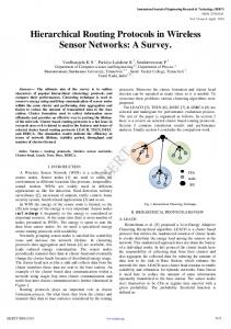
B. GEAR-R routing protocol for coal mine GEAR-R focuses on hybrid mobile network model on the base of GEAR protocol. To the power supply node in the tunnel, assuming that they are static and the location is known, can be directly used GEAR routing protocol. To the node of coal face, assuming that the nodes on the hydraulic support are static and the nodes on the mining machine can move and the number is more than one. The mobile node is responsible for collecting sensor data[6]. C. BRIT routing protocol BRIT (Bounce Routing in Tunnels) is an on–demand routing protocol and its route discovery scheme is similar to AODV [7] and DSR [8]. It integrates physical propagation models, tunnel geographic models and location information to provide the near optimal routing paths. It uses a location based route discovery and routing message suppressionfor data forwarding in underground tunnel environments. To determine the optimal path, a parameter forwarding metric is used, that is applicable in location-based routingschemes [9]. D. Data Aggregation Model for underground coal mine (DAM) In this model, all sensor nodes were divided into different grid clusters by geographical information and the network topology was composed of two levels [10]. The lower level including all ordinary nodes was responsible for environment monitoring and delivered the data to the upper level, all the upper level nodes took charge of local data collection and establishment of the routing paths to sink through the direct diffusion scheme. E. Energy Efficient sensor placement for underground coal mine (EESP) In this scheme Wireless sensor nodes, deployed along two sides of tunnel, first collect information on the environment and then send to the Base Station through the multi-hop way. The BS, placed at the junction of branch tunnel with main tunnel and powered by wired power source [11]. To reduce the energy dissipation the node are placed as shown in figure 6.
Figure: 6 Node Arrangements in Tunnel [11]
In this multi-hop architecture nodes which are near to base station have a bulk of messages to send. So to balance the energy dissipation, the distance between nodes gets decreased in the direction of base station.
ISSN : 2229-3345
Vol. 3 No. 6 June 2012
183
Hariom Agrawal et al./ International Journal of Computer Science & Engineering Technology (IJCSET)
F. A Multi-Hop Recursive routing Algorithm (MHRR) This algorithm uses a recursive approach to find a best possible path through different hopes. The algorithm uses routing request order frame (RROF) and routing reply state frame (RRSF). A node first broadcast a RROF, when neighbour receives RROF, the hop count will be increased by 1 and receiver’s address and RSSI will be inserted into the original frame for a new frame. Before neighbour nodes forming the new RROF, firstly, algorithm check whether the received RROF contains their self-address and Hop is greater than a certain value Hm, if one of them happens, the operation should be stopped and no longer transmit RROF. By this recursive approach it will find the path to the destination. III.
Comprehensive Analysis of Routing Protocols
The protocols which are effective or efficient in ad-hoc routing or in wireless sensor network may or may not be useful for WUSNs as there are several environmental differences between WSN and WUSN. The differences are shown in table 1. In the WUSNs, most sensors will be deployed by drilling a hole for each one, and thus, detailed location information can be recorded at the time Table: 1- comparison between WUSN and other Wireless Sensor Networks
Parameter Establishment Frequency Application Environment Power consumption Deployment Cost Protocol
WUSN 2004 Impulse Radio Ultra Wide Band (IRUWB) Agriculture, Coal Mines Soil, rock and narrow Coal mines More Difficult More GEAR, GEAR-R
WSN 1990 Radio waves Environment Monitoring Open and Terrestrial Less Easy Less AODV, DSR etc.
of deployment. So in this case, geographical routing protocols may be efficient. But if the node is randomly scattered then these routing protocol may not be efficient. Some protocols consider the remaining energy in deciding the path whereas several protocols consider each node equal for the path determination. It may be more energy efficient to route data to a terrestrial device, which could relay it through a series of terrestrial links rather than the high-cost underground links. For a WUSN deployed within and around an underground mine, it will be more power-efficient to route data through sensors in open-air mine tunnels than through those devices embedded in the soil and rock. Additionally, link costs will vary over time as soil conditions, such as water content, and depth etc. protocols must be aware of the unique challenges of the underground environment in order to maximize the power efficiency and thus, the network lifetime. The comparative analysis for the protocol used for underground mine are given in table 2. Table: 2 Comparison of routing protocol of underground coal mine
Protocol/ model
Update destination
Structure
Route computation
GEAR BRIT
Neighbor Neighbor
DAM
Cluster-head
Flat Flat/ cylindrical Hierarchical
EESP
Neighbor
MHRR
Multi-hop Neighbor
ISSN : 2229-3345
Flat/ type Flat
Chain
Recursi ve
Route metric
Reactive Reactive
Hello message required No Yes
Yes No
Proactive
Yes
No
Reactive
No
No
Reactive
Yes
yes
Energy Forward metric Shortest distance Shortest distance Shortest distance
Vol. 3 No. 6 June 2012
184
Hariom Agrawal et al./ International Journal of Computer Science & Engineering Technology (IJCSET)
IV.
Conclusion
Researchers all over the world are working on different areas such as- routing, application, power management, security and deployment etc. This paper focuses on the concept of WUSNs in which sensor devices are deployed completely underground. There are various applications of underground sensing, such as soil monitoring for agriculture. There are significant benefits of WUSNs over current sensing solutions including complete network concealment, ease of deployment, and improved timeliness of data. These benefits enable a new and wider range of underground sensing applications, from sports field and garden monitoring. Various routing protocols have been studied and compared on several parameters such as – structure, route metric, recursive and the update destination.
REFERENCES [1]
Erich P. Stuntebeck, Dario Pompili, TommasoMelodia, Wireless underground sensor networks using commodity terrestrial motes, Proc. Wireless Mesh Networks, 2nd IEEE Workshop, Virginia, USA, 2006, pp. 112-114, 2006. [2] Ian F. Akyildiz, Weilian Su, YogeshSankarasubramaniam, and ErdalCayirci, “A survey on sensor networks”, IEEE Communication magazine, 2002. [3] Campbell Scientific, Inc. Available from: . [4] I. Akyildiz and E. Stuntebeck, “Underground wireless sensor networks: research challenges”, ad Hoc Networks, June 2006. [5] Haifeng Jiang, JianshengPeng, Wei Peng, “Nonuniform clustering routing protocol for tunnel wireless sensor network in underground mine”, International Conference on Wireless Communications & Signal Processing, 2009. [6] Yu Y, Govindan R, Estrin D, “ Geographical and energy aware routing: A recursive data dissemination protocol for wireless sensor networks.,” UCLA Computer Science Department Technical Report UCLA/CSD-TR-01-0023, May 2001 [7] C. Perkins, E. Belding-Royer, and S. Das.RFC 3561 - Ad hoc on-demand distance vector (AODV) routing.Technical report, Internet Engineering Task Force (IETF), Jul. 2003. [8] D.B. Johnson, D.A. Maltz, and Y.C. Hu.The Dynamic source routing Protocol for mobile ad-hoc networks (DSR), Technical report, IETFMANET Working Group, Jul. 2004. [9] Di Wu, Renfa, Li LichunBao “AHolistic routing protocol design in undergroundwireless sensor networks” The 4th International Conference on Mobile Ad-hoc and Sensor Networks, Wuhan, China, IEEE Computer Society 2008, ISBN 978-0-7695-3457-2, December 10-12, 2008. [10] T.Minming , N Jieru , W Hu , Liu Xiaowen “A Data aggregation model for underground wireless sensor network” Vol-1, pp344-348 , WRI world congress on computer science and information engineering, 2009 . [11] Haifeng Jiang, JianshengQian, Wei Peng, “Energy efficient sensor placement for tunnel wireless sensor network in underground mine” Power Electronics and Intelligent Transportation System (PEITS), 2nd International Conference, 01/2010
ISSN : 2229-3345
Vol. 3 No. 6 June 2012
185