RTL Formal Verification of Embedded Processors P. Bavonparadon and P. Chongstitvatana Department of Computer Engineering Chulalongkorn University Phayathai road, Bangkok, 10330, THAILAND E-mail:
[email protected],
[email protected] Abstract This paper presents a technique for formal verification of processors. The verification process is performed at the RTL level of implementation, which has the advantage of being synthesizable by a synthesis tool. Cadence SMV is used as the verification tool. It employs the symbolic model checking technique. A stepwise verification method is proposed where the details of design are increased in each step. This method facilitates the error finding process. The proposed technique can reduce the complexity of the verification process and enables it to be completed in a reasonable time. The technique is illustrated on a simple processor used in an embedded web server. The design is verified successfully. Keywords: Formal Verification, RTL (Register Transfer Level), Cadence SMV, Processor Verification, Symbolic Model Checking, Stepwise Verification Method 1. Introduction This paper presents a formal verification of a processor, which is designed for an embedded web server [1]. The verification process is applied to the implementation of the processor at RTL (Register Transfer Level). The RTL implementation can be synthesized by synthesis tools. This makes the method suitable for practical use. Cadence SMV [2] is used as a verification tool. This tool is based on symbolic model checking [3,4] which is a technique in model-based verification [5]. In recent years, there are many applications of formal verification for processor validation such as [6,7,8,9,10,11]. Many works verify the commercial processors [6,7,8]. Proof-theoretic approaches [5] are the most popular techniques for verifying processors [8,9,10,11] as they are suitable for verifying large circuits. However, these approaches have some drawbacks. It requires mathematical expertise and it is not yet easy to automate. Therefore, these approaches are only used in research or in companies which have expert formal verification team. In addition, many works on processor verification do not verify a whole processor but they verify only some parts [6,9,11]. This is because the size of the whole processor in full details is too large to be verifiable. Other approaches are model-based approaches. These approaches are often used to verify control circuits [12,13,14], protocols [15], and asynchronous control circuits [16]. Although there is an application of these approaches for verifying processors [17] but it is the verification at behavior level. There are only a few
research that apply model-based approaches to verify processors and there are only few works which verify a whole processor. There is no research that uses modelbased approaches to verify processors at RTL because it has too many details. This paper uses symbolic model checking technique to verify the processor at RTL level. This design level has sufficient detail for synthesizing a real chip. The advantage of this technique is that it is highly automated hence it does not require a mathematician to perform the verification. Therefore, small group of researchers or small size companies can apply this technique in their verification process. This paper proposes the stepwise verification that divides the verification process into many steps. The first step has the least detail and the last step has the most detail. This method makes the error finding easier. Some abstraction techniques which speed up the verification process are also presented. The rest of this paper is organized as follows. Section 2 introduces symbolic model checking technique. Section 3 describes the processor. Section 4 presents the detail of formal verification of the processor. Section 5 concludes the paper. 2. Symbolic Model Checking Symbolic Model Checking [3,4] is a technique belongs to model-based approaches. This technique is suitable for verifying finite state systems. The task of symbolic model checking can be broken down into three phases: modeling, specification, and verification. The first task is to represent system under consideration in a precise model that can be accepted by a model checking tool. Often we need to use abstraction to eliminate irrelevant or unimportant details from the design to reduce the amount of resource required by the verification tool. Cadence SMV (Cadence Symbolic Model Verifier) [2] is used. It is a symbolic model checking tool based on binary decision diagram (BDD) [18]. This tool accepts SMV language which is designed for the verification task. SMV language is similar to a hardware description language so it suits for representing hardware circuits. This language can express the specification in a temporal logic Computation Tree Logic (CTL) [19]. CTL is used to express temporal properties such as the absence of deadlock etc. Cadence SMV tool creates state transition graphs from SMV language source codes. It uses binary decision diagram to represent state transition relations and performs the verification process by using these relations. The use of binary decision diagram is an
important factor in the success of symbolic model checking technique. The second task is to write the specification using CTL. The CTL properties are composed of atomic propositions, boolean connectives, and temporal operators. Atomic propositions are used to represent state variables in the system. Boolean connectives consist of conjunction operators (∧), disjunction operators (∨), and negation operators (¬). Temporal operators are path qualifiers (A or E) and temporal modalities (F, G, X, or U). Path qualifiers define that the property should be true for all execution paths or some execution paths. Temporal modalities specify the sequence of events on the execution path. Each temporal modalities have specific meaning as follows: 1.
2. 3. 4.
F ϕ (“ϕ holds sometime in the future”) is true of a path if there exits a state on the path for which the formula ϕ is true. G ϕ (“ϕ holds globally”) means that ϕ is true at every state on the path. X ϕ (“ϕ hold in the next state”) means that ϕ is true in the second state on the path. ϕ U ψ (“ϕ holds until ψ holds”) means that there exists some state on the path for which is ψ true, and for all states preceding this one, ϕ is true.
An atomic proposition is true when the corresponded state variables have suitable values. The truth values of propositions connected by boolean operators depend on the truth value of each atomic proposition. The propositions with universal path quantifiers (A) are true when the properties are true for all execution paths. The propositions with existential path quantifier (E) are true when the properties are true for some execution paths. Furthermore, the properties of verified system are true when these properties are true for all initial states. The examples below are some examples of CTL, which show the expressiveness of this logic. • • • •
AG(Reg → AF Ack): it is always the case that if the signal Reg is true, then eventually Ack will also be true. AG AF DeviceEnabled: DeviceEnabled holds infinitely often on every computation path. AG EF Restart: from any state, it is possible to get to the Restart state. AG(Send → A(Send U Recv)): if Send holds, then eventually Recv is true, and until that time, Send remains true.
The third task is verification (after modeling and specification). The verification process is fully automatic. When some properties are false, Cadence SMV tool will produce the counterexamples of the problem cases. These counterexamples can be used to find sources of the errors. 3. Embedded Processors The processor verified in this paper is designed for an embedded web server [1]. This processor is sufficiently
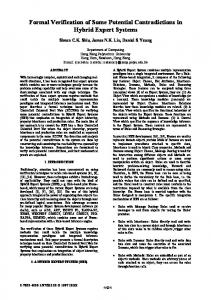
small and can be used in remote control systems via Internet. It is a 16-bit load/store architecture that the computation performs only with the registers and there are only load and store instructions which can communicate to the memory. The memory address bus and memory data bus are 16-bit wide. The program memory and data memory are separated. Figure 1 shows the datapath of the processor. This processor does not use pipeline and does not support interruption signals. The processor is designed at RTL level. It has sufficient detail of the processor such as transitions of the internal control signals and internal structure of the processor etc. The design is written in Verilog hardware description language. The instructions of this processor is divided into 3 groups: computation instructions, jump instructions, and load/store instructions. There are four 16-bit registers and two flags: carry and zero. Table 1 shows instruction set of this processor. 4. Processor Verification The verification in this paper, means the refinement verification [2] that verifies the functional equivalence between the implementation and the specification. It verified that the important signals of the implementation have the same values as the corresponding signals of the specification. The refinement verification can be performed using both simulation method and formal verification. However, formal verification can guarantee the correctness of verification result better than simulation method. The verification is divided into several incremental steps, where the details of the processor are increased at each step. The first step has the least detail and the last step has a full detail. Each step contains only the necessary detail for verifying the goal of that step. This stepwise technique also helps in locating and correcting the errors in the design that are discovered during the verification process. The verification process is composed of the following steps: 1. Verify that the processor fetches instructions from the program memory correctly. The verification goal of this step is that the value of IR (Instruction Register) in the specification and the implementation are the same. 2. Verify that the value of opcode is correct. This signal is the output of uninterpreted function. This function defines the relation between IR and opcode. The detail of uninterpreted function is described in Section 4.2. 3. Verify that the values of registers in the register file are correct (there are 4 registers) and verify that the values of flags are correct (carry flag and zero flag). This step verifies only computation instructions. 4. Verify that the value of PC (Program Counter) is correct. This step verifies jump instructions. 5. Verify that the values of registers in the register file, flags, and PC are correct. This step verifies load/store instructions.
Data Bus
Instruction Code
16 16
ir_load
Instruction Address PC
opcode
IR
PC Decoder offset
immediate 11
pc_load
pc_sel
mem_sel
pc_sel1
16
reg_sel ld_sel reg_load
opcode
16
Register File
8
a_out
b_out
ALU
Data Bus 16
Sign Extension
C
Z
op_sel
mem_sel1 d_data_out Address Bus
16
Figure 1. Datapath of the processor Table 1. Instruction set of the processor (r = register[A,B,T,SP], i = immediate, ad = address) Instruction ADD r ADDI r, i SUB r SUBI r, i AND r ANDI r, i ORR r ORRI r, i XOR r XORI r, i COM r ROL r ROR r NOP 6.
Description [r] = [r] + [T] [r] = [r] + immediate [r] = [r] - [T] [r] = [r] - immediate [r] = [r] & [T] [r] = [r] & immediate [r] = [r] | [T] [r] = [r] | immediate [r] = [r] ^ [T] [r] = [r] ^ immediate [r] = ~[r] Rotate left [r] by c flag Rotate right [r] by c flag No Operation
Verify that the values of registers in the register file, flags, and PC are correct. This step verifies every instructions.
4.1 Specification and Implementation of Processor The specification of the processor is written in SMV language. This specification describes the instruction set architecture (ISA) of the processor. It is a behavioral level description of the processor. It describes a sequential circuit and its signals such as IR, PC, register file, flags, RAM, and ROM etc. The state transition function of the specification has the same transition as the control unit of the implementation. The specification
Instruction LUI r CLC STC JNZ ad JNC ad JMP ad LDB r LDS r STB STS LPC SPC R2T r
Description Load upper immediate to [r] Clear carry flag Set carry flag Jump if not zero Jump if not carry Unconditional jump Load from mem[B] to [r] Load from mem[SP] to [r] Store [T] to mem[B] Store [T] to mem[SP] Load from mem[SP] to [PC] Store [PC] to mem[SP] Move [r] to [T]
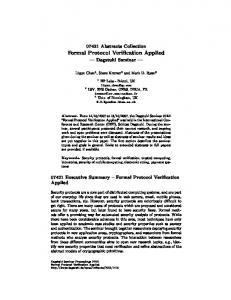
and the implementation will start and finish the execution of every instruction in sync. For this reason, it is possible to compare the value of signals in the specification and the implementation. The implementation is also written in SMV language. It describes the detail of the processor designed at RTL. The SMV language implementation has the same module and hierarchy of the processor as in the Verilog implementation. Figure 2 shows some part of datapath with respect to IR. From this figure PC value becomes the address of ROM. The data port of ROM connects with the input of IR. In the fetch state IR will save the present instruction
from ROM following the clock that control signals set to active. This is an example of the SMV source code of the specification and the implementation. In the state that fetches an instruction from ROM (program memory) the code of the specification is: next(ir_ab) := rom_mem_ab[pc_ab];
The IR value is assigned with ROM data, and the address of ROM is equal to PC value. The implementation code is: prog_en:=0; ir_ld:=1;
The prog_en is a chip enable signal of ROM. In the other states its value is '1' (disable ROM) but in this state its value is '0' (enable ROM). The ir_ld is the load signal of IR module in this state its value is '1' (load to IR). This example shows that the behavior model of specification is more understandable than the RTL model of implementation. next_pc_1
pc_out
...
Furthermore, the specification and the implementation use the same uninterpreted function. Data size reduction: The data size is abstracted to 1 bit to reduce the number of possible states. The use of uninterpreted functions is appropriate as it is necessary to consider only that the data in the specification and the implementation are the same or not. Not verify the effect of carry flag to ALU: The uninterpreted function representing ALU depends on both the input of ALU and the carry flag. The possible state is too large for the tool to handle. By omitting the carry flag, 24 state variables can be eliminated. The possible state is reduced 224 times. This allows the tool to verify the whole design successfully. In addition, the connection line between the carry flag and ALU can be verified by simulation method later, because the possible state of this line is small. 4.3 The Detail of Verification Figure 3 shows a part of SMV language source code which define the relations between signals in the specification and the implementation. These assertion are automatically converted to CTL by Cadence SMV tool. These assertions are:
PC
1.
WORD pc_ld
2. WORD rom_data
ROM
ir_out IR WORD
3.
WORD prog_en
ir_ld
Figure 2. Some part of datapath with respect to IR 4.2 Abstraction Technique in Specification and Implementation By the nature of symbolic model checking technique, it has state explosion problem. The execution time and memory used in the verification process increase exponentially with the complexity of the verified system. Therefore, some abstraction techniques must be used to reduce the complexity of the processor. These abstractions are: Uninterpreted function: To reduce the complexity, the detail of combinational logic is not verified. Uninterpreted functions [2] are used to represent this detail. Uninterpreted functions are multi-dimension arrays that are not initialized. Any function value can be assigned to uninterpreted functions. The combinational logic circuits represented by uninterpreted functions are arithmetic logic unit (ALU) and adder circuit for PC. In addition, uninterpreted functions are used for defining the relations between IR and many signals such as opcode, inst_mode (instruction mode), rs (source and destination register) and imm (immediate value) because the actual data width has been abstracted away.
4.
5.
The lemma1 declares that IR value of the implementation (ir_out) must equal to IR value of the specification (ir_ab). This assertion must hold in every state. The lemma2 declares that opcode value of the implementation (opcode) must equal to opcode value of the specification (opcode_ab). This assertion must hold in every state. The lemma3 declares that register values in the register file of the implementation (regfile.ra, regfile.rb, regfile.rsp, regfile.rt) must equal to register values in the register file of the specification (ra_ab, rb_ab, rsp_ab, rt_ab). This assertion holds only in the FETCH0 state, which the processor fetches a new instruction from program memory. In this state, the results of last instruction were stored and the processor did not start to execute a new instruction. The lemma4 declares that carry flag and zero flag of the implementation (c, z) must equal to carry flag and zero flag of the specification (c_ab, z_ab). This assertion only holds in the FETCH0 state. The lemma5 declares that PC value of the implementation (pc_out) must equal to PC value of the specification (pc_ab). This assertion must holds in the FETCH0 state.
4.4 Verification Result During the verification process, we discover an error in the implementation of the processor. There is a mistake in the COM (Complement) instruction. The specification defines that this instruction affects value of the zero flag, but the verification tool indicates that this instruction of the implementation does not affect the zero flag. This error has escaped the test by simulation method which the processor has been subjected to extensively before the formal verification.
The Cadence SMV tool works on computer that uses Linux operating system. It has Pentium III 1 GHz processor and 2 Gbytes memory. The tool finishes verification process in 30 minutes and uses memory about 1 Gbytes. layer lemma1: ir_out := ir_ab; layer lemma2: opcode := opcode_ab; layer lemma3: if (pstate=ST_FETCH0) { regfile.ra := ra_ab; regfile.rb := rb_ab; regfile.rsp := rsp_ab; regfile.rt := rt_ab; } layer lemma4: if (pstate=ST_FETCH0) { c := c_ab; z := z_ab; } layer lemma5: if (pstate=ST_FETCH0) pc_out := pc_ab;
Figure 3. The relation between the implementation and the specification 5. Conclusion This work shows the application of formal verification to verify the processor designed for an embedded web server. The verification performs at the level of RTL which has the sufficient details for synthesizing to physical circuits. Cadence SMV is used as the verification tool. It is based on symbolic model checking technique. The verification of the implementation at RTL by symbolic model checking technique has never been done before because of the state explosion problem. This paper presents many techniques to reduce the complexity of the processor so that the verification process can be completed. Furthermore, this paper proposes the stepwise verification, which divides the verification process into several incremental steps that details are increased from the first step to the last step. Some error has been detected which has not been discovered by the previous test by simulation. It demonstrates the application of formal verification to an RTL implementation of processors. Because the symbolic model checking method can be largely automated, it is applicable to the real world industry. The future work will be to create a tool for translating an implementation in SMV language into Verilog HDL that can be used for synthesizing circuits. Another work is to create a tool for translating the specification, which describes ISA, in SMV language into a simulator program. These tools will allow the formal verification process to be integrated into the development cycle of real world applications. 6. Acknowledgement
Prapon Bavonparadon is supported by Chulalongkorn University's scholarship given in H.M. King Rama IX 72nd Anniversary. References [1] K. Piromsopa, Development of A Reconfigurable Embedded Web Server, Master Thesis, Chulalongkorn University, 2000. (in Thai) [2] K. L. McMillan, Getting started with SMV, http://www-cad.eecs.berkeley.edu/~kenmcmil/ tutorial.ps, 1999. [3] K. L. McMillan, Symbolic Model Checking, Ph.D. Thesis, Carnegie Mellon University, 1992. [4] J. R. Burch, E. M. Clarke, K. L. McMillan, D. L. Dill, L. J. Hwang, "Symbolic Model Checking: 10^20 states and beyond", Information and Computation, Vol. 98, No. 2, June 1992, pp. 142-170. [5] T. Kropf, Introduction to Verification, Springer, 1999.
Formal
Hardware
[6] A. Biere, E. Clarke, R. Raimi, and Y. Zhu, "Verifying safety properties of a PowerPC microprocessor using symbolic model checking without BDDs", Proceedings of the 11th International Conference on Computer Aided Verification (CAV'99), 1999. [7] D. P. Appenzeller, and A. Kuehlmann, "Formal Verification of a PowerPC Microprocessor", Proceedings of the International Conference on Computer Design (ICCD'95), 1995. [8] S. P. Miller, and M. Srivas, "Formal Verification of the AAMP5 Microprocessor: A Case Study in the Industrial Use of Formal Methods", Proceedings of the Workshop on Industrial-Strength Formal Specification Techniques (WIFT'95), 1995. [9] R. Hosabettu, M. Srivas, and G. Gopalakrishnan, "Proof of Correctness of a Processor with Reorder Buffer using the Completion Functions Approach", Proceedings of the 11th International Conference on Computer Aided Verification (CAV'99), 1999. [10] P. J. Windley, "Formal modeling and verification of microprocessors", IEEE Transactions on Computers, Vol. 44, No.1, January 1995, pp. 54--72. [11] J. R. Burch, "Techniques for Verifying Superscalar Microprocessors", Proceedings of the 33rd Design Automation Conference (DAC'96), 1996. [12] A. A. Mir, S. Balakrishnan, and S. Tahar, "Modeling and Verification of Embedded Systems using Cadence SMV", Proceedings of the 2000 Canadian Conference on Electrical and Computer Engineering, 2000. [13] H. Choi, B. Yun, Y. Lee, and H. Roh, "Model Checking of S3C2400X Industrial Embedded SOC Product", Proceedings of the 38th Conference on Design Automation Conference (DAC'2001), 2001.
[14] A. Goel, and W. R. Lee, "Formal Verification of an IBM CoreConnect Processor Local Bus Arbiter Core", Proceedings of the 37th Conference on Design Automation Conference (DAC'2000), 2000. [15] L. Barakatain, S. Tahar, J. Lamarche, and J. Gendreau, "Practical Approaches to the Verification of a Telecom Megacell using FormalCheck", Proceedings of the 2001 Conference on Great Lakes Symposium on VLSI, USA, March 2001. [16] V. Vakilotojar, and P. A. Beerel, "RTL Verification of Timed Asynchronous and Heterogeneous Systems using Symbolic Model Checking", Proceedings of the Asia and South Pacific Design Automation Conference (ASP-DAC'97), 1997. [17] R. Jhala, and K. L. McMillan, "Microarchitecture Verification by Compositional Model Checking", Proceedings of the 13th International Conference on Computer Aided Verification (CAV'2001), 2001. [18] R. E. Bryant, "Graph-Based Algorithms for Boolean Function Manipulation", IEEE Transactions on Computers, Vol. 35, No. 8, August 1986, pp. 677-691. [19] P. Chauhan, E. M. Clarke, Y. Lu, and D. Wang, "Verifying IP-Core based System-On-Chip Designs", Proceedings of the 12th International ASIC/SOC Conference, 1999.