what object- oriented software development methodol- ... Well-known database development tools, which .... application of previously defined functions.
Programming and Computer Software, Vol. 25, No. 5, 1999, pp. 276–281. Original Russian Text Copyright © 1999 by Terekhov, Romanovskii, Koznov, Dolgov, Ivanov.
RTST++: Methodology and a CASE Tool for the Development of Information Systems and Software For Real-Time Systems A. N. Terekhov, K. Yu. Romanovskii, D. V. Koznov, P. S. Dolgov, and A. N. Ivanov St. Petersburg State University, Bibliotechnaya pl., 2, St. Petersburg, 198904 Russia Received January 29, 1999
Abstract—Recently, two largest-scale branches of software development, where CASE tools are efficiently used—information systems and real-time control systems— are observed to close in. In large information systems, a software response rate problem arises when servicing a big number of clients. As a rule, real-time control systems not only control specific equipment, but also work with a database. In this paper, the RTST++ object-oriented methodology is presented, which is created on the basis of UML, SDL, and ROOM, with certain elements of the structured approach (basically, for the convenience of relational database development) and reflects the tendencies mentioned above. Along with this, a CASE tool implementing this methodology, RTST++, is presented.
INTRODUCTION The increasing complexity of modern software caused the development of a special branch of science, Software Engineering, whose main goal is to create efficient methods for complex software development. Object-oriented methodologies for software development have been intensively developed beginning from the end of the 1980s. In 1997, OMG acknowledged the UML standard [1] that appeared as a result of merging a number of well-known methodologies. Up to the present moment, several companies offered UMLimplementing CASE tools. Another object-oriented approach used in the design of RTST++ is the ROOM methodology [2], designed for real-time system development. On the other hand, for 20 years the ITU international committee has been developing standards for telecommunication system development: SDL [3], MSC [4], etc. A large number of companies, mostly in Europe, produce software that implements these standards. From the third point of view, the structured methodologies for software development—SADT [5, 6], the Yourdon method [7], etc.—have been developed beginning from the 1970s. At the present time, these methodologies have taken their place in the field of information system development. They are efficient for the overall analysis of systems and, besides, are successfully used to design relational databases and automatically generate forms, reports, and the like. These three branches exist independently and apart: with different methodological bases, different producing companies, etc. However, some integration of these approaches is observed nowadays.
Within the SDL world, a certain opinion dominates what object- oriented software development methodologies may be used for system analysis, but its further specification is to be done using SDL. A formal specification of translation rules (OMT) [9] was designed within the framework of the INSYDE international project [8]. Many companies have implemented this idea to this or that extent in their SDL products. Well-known database development tools, which were created on the basis of the structured approach to the software development and now constitute an autonomous branch, offer ways to be integrated in CASE tools implementing the UML. The fact that diagrams of the UML classes are extensions of the entity–relationship diagrams used for database structure specification provides the basis for such integration. In this work, we describe the RTST++ object-oriented methodology and the CASE tool with the same name, which implements it. The RTST++ methodology is chiefly based on the UML [1], SDL [3], and ROOM [2], and reflects the integration tendencies mentioned above. Along with features that are standard for the object-oriented approach, additional opportunities are added to the RTST++ aimed at two special fields: software for information systems and software for realtime systems. Such an approach often spares the additional adjustment of a CASE tool to be applicable in this domain; if, however, such an adjustment is needed, it will be much easier and cheaper than, for instance, the adjustment of CASE tools implementing the UML. RTST++ does not claim to be able to cover all functions of program products in the corresponding fields. At the same time, taking into account the modern maturity level of local- and wide-area information networks and the increasing complexity of software, the client/server technology becomes more and more popular
0361-7688/99/2505-0276$22.00 © 1999 åÄàä “ç‡Û͇ /Interperiodica”
RTST++: METHODOLOGY AND A CASE TOOL
in information systems; i.e., many information systems become dramatically event-driven; this aspect is extensively investigated in real-time system development methodologies. On the other hand, large distributed real-time systems, as a rule, need to store, access, and transfer large amounts of data, for example, traffic and authentication information and not only control signals and traffic data. Thus, RTST++ is suitable for software development in both fields; however, it is the most efficient for their intersection. RTST++ (the methodology and the CASE tool1 is a descendant of the RTST [12, 13]. It has been developing for the last ten years at the Mechanical and Mathematical Department of St. Petersburg State University. In the present paper, we present the RTST++ methodology basics (process and models2; then, the corresponding tools are described. After that, specific features of RTST++ (the methodology and CASE tools), designed for information system and real-time system development, are discussed. BASICS OF THE RTST++ METHODOLOGY Considering no general aspects of the software development process here (see it in, e.g., [16]), we now list models used in RTST++ to describe the system being developed: • System requirement model: (i) descriptive model describes some system requirements in a text form; (ii) utilization model describes requirements for the system imposed by its environment, i.e., answers the question, “how and for whom must the system operate?”; (iii) functional model classifies situations in which the system is used and describes the decomposition of functions into subfunctions. Answers the question, “how should system functions be implemented in terms of their subfunctions?”. • Dynamic model: (i) object model describes roles of system objects; answers the question: “which objects interact during the execution of the system functions?”; (ii) interaction model describes scenarios of object interactions with each other and with users; answers the question: “how do objects interact with each other while performing system functions?”; (iii) behavior model describes system object behavior algorithms; answers the question “how should an object behave to implement the system functions?”. • Static model: class model describes the system’s internal structure and the structure of the data used; answers the question: “how should the system be organized inside?”. 1 The previous version is described in [10, 11]. 2 One can find a more formal definition of RTST++ models in [14].
PROGRAMMING AND COMPUTER SOFTWARE
Vol. 25
277
In RTST++, significant attention has been payed to the connectivity of the models, the control of project information integrity both within the same model or different models. METHODOLOGY Requirement Model The work over a system in RTST++ begins with the construction of a descriptive model containing, first of all, the customer’s primary requirements. Among these requirements, both functional and any other requirements (e.g., efficiency, cost, etc.) may be present. The descriptive model is stored in RTST++ as a plain text and formally is not connected with other models. This model may be used also for the final specification of nonfunctional requirements. On the basis of the customer’s requirements, the full list of functional requirements to the system is formed. It is presented in terms of the utilization model and the functional model. The final technical specification of the system can be generated in accordance with the RTST++ requirement model in a form needed by the customer (an international or corporate standard, etc.). The utilization model is designed in RTST++ to describe the integration of the system in its environment. In terms of this model, all users of the system and all its functions (utilization cases) are described in a form in which they are distinguished by these users. Then, classes may be associated with users; for utilization cases, diagrams of the same type can be generated. Further decomposition of the system functions is performed using the functional model. The functional model consists of a set of function trees; the roots of these trees are utilization cases. A tree may contain nodes of two types: a function itself and an application of previously defined functions. In addition, a function may have a group property, which means that its child functions, in fact, are located instead of it at the same position. The connection of an ancestor node with descendant nodes may have a label describing its behavior [14, 15]. The utilization model in RTST++ is a subset of the UML model with the same name. The job that is done in the UML by the part of the utilization model which is not included in RTST++ is to be done here using the functional model, which is a variant of the functional model used in structured methodologies of software development. The RTST++ functional model is based on the functional model from [15]; however, some details were removed and others were added to it. In RTST++, there is no need to use the functional model as often as in [15], since we do not want to urge the developer to use an algorithmic method of system development. Added features are the use of functions, function groups, and connection with the utilization model. No. 5
1999
278
TEREKHOV et al.
Dynamic Model The dynamic model describes the system behavior; that is, the interaction of its different components with each other, the interaction of the system with its environment, and the behavior of those components. In the first stages of development, one may follow one of two strategies. The first one is to specify system classes at first, and then objects and interaction scenarios. The second strategy suggests the reverse order of the development (see [16] for more detail). The first strategy is used more often when the developer is familiar with the subject domain; the second strategy is used, if the developer should study the unfamiliar subject domain at the stage of the analysis. The main goal of the object model is to describe different roles that the instances of system classes may play. Each function from the functional model of RTST++ may be assigned an object diagram whose purpose it is to describe the typical “configuration” of objects involved in the implementation of the function, along with relations among these objects. When using the object-oriented approach, the implementation of system functions is a result of the cooperation of several objects. The main elements of this cooperation are objects– roles and relations among them. The relation between the object model and the scenario model is the same as in the UML. An automatic class diagram generation using an object diagram is provided. When implementing a function, it is convenient to represent the dynamics of object interaction in the form of scenarios. In these scenarios, objects–roles, defined on the object diagram for the given function or its calling functions, take part. A scenario is a sequence of events sorted by time, typically, these messages are sent and received by objects. The construction of scenarios for a given function is begun with the definition of “straight paths,” i.e., paths of the ideal execution of the function. At this stage, the boundary, erroneous situations, special cases, etc. are excluded from the consideration. Later scenarios are constructed for these cases as well, or they are specified by other means. The behavior model describes the behavior of the system constituent classes using an extended finite automaton and is introduced in RTST++ in two notations: in STD [2] or SDL [3] style. In practice, the behavior model defines processes in the system in terms of states,3 events,4 and actions.5 Further, we shall discuss the behavior model of a separate class. It is possible to begin the construction of such a model with the 3
State is a stable state of an object, when it is ready to receive interaction requests from other objects. Some activity of the object (e.g., input and output) may be associated with a state. A state may be complex; i.e., it may contain substates. 4 Event is an act of a message receiving or timer expiration. 5 Action is a message sending, timer, setting; a block of the code in a target language.
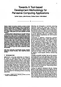
analysis of all scenarios in which objects–roles of the given class take part. The design of the system behavior (the behavior of all its classes) on the basis of scenarios (rather than directly) allows one to represent common processes in the software in a more visual form and proceed from it to the construction of the internal behavior of these process participants. For the scenario model, we use a variant of the MSC notation [4, 17]. Moreover, RTST++ enables binding this model with the model of classes in a different way than it is done in UML: In RTST++, one may choose messages in scenarios (and also in the behavior model) from interfaces described in the class model. Note also that no formal relation between SDL and MSC is presumed in the SDL methodology; for example, in such a well-known product as SDT [19] this relation is exclusively dynamic. Static Model After the basic system scenarios have been created, one may proceed to the specification of their members—objects; i.e., to the class model construction. The class model is built during the entire software development process (see [16] for more detail). In RTST++, the class model may contain the following entities: • class is the description of a group of similar objects; • template is a parameterized class with the possibility to derive from it a normal class by substituting parameter values; • interface is a description of class interaction rules; • representation is an analogue of the VIEW construct in the SQL. An example of a class diagram depicting classes, ports, and interfaces is shown in Fig. 1. The RTST++ class model implements a rather complete subset of the UML classes. In addition, it includes interfaces and ports adopted from ROOM and significantly extended. The RTST++ class model also contains database scheme modeling means. Tools RTST++ is a package of interdependent editors, combined in an integrated development environment. It includes: • text editor; • utilization cases editor; • function editor; • class editor; • object editor; • STD diagram editor; • SDL diagram editor; • interaction scenario editor;
PROGRAMMING AND COMPUTER SOFTWARE
Vol. 25
No. 5
1999
RTST++: METHODOLOGY AND A CASE TOOL
• script editor; • open library for the repository access. All project data are stored in a single database, the repository, which may be located in any relational DBMS. Besides, there is a library of OLE objects for accessing the repository from both the RTST++ built-in script editor and from any environment supporting OLE automation. RTST++ uses VBScript, a subset of Visual Basic, as the script language. INFORMATION SYSTEM DEVELOPMENT RTST++ supports the development of the traditional levels of information systems: database schemes, business logic, user interface (screen forms). For the creation of a database scheme, we use the class model containing an extension for databases. In the class model, there are several elements aimed directly at the database design. First of all, this is a special attribute type index with the possibility to multiply indices by associations (foreign keys). The second item is an analogue of the VIEW construct of the SQL; it is designed for visual editing of complex queries. Note that these opportunities are not available in UML, SDL, and ROOM. If a database scheme does not extend beyond the traditional relational DBMS, then the further generation of the database itself and the provision of access to it are obvious. If, on the contrary, certain elements of the object-oriented approach (firstly, inheritance) were used in the database scheme, then either an object-oriented dedicated DBMS or special means for the work with data are required. However, it may be convenient to work with a relational database in terms of the class model. For this purpose, RTST++ provides a generator of class library that assumes the main part of the interaction with the database without using SQL queries. The standard RTST++ set up package includes the script generating the database scheme using SQL DDL and an object-oriented library for accessing the database in the form of C++ classes and OLE Automation objects. Tools for the creation of screen forms in RTST++ are now under construction, but their main ideas are already clear. Basically, the user interface in information systems consists of different screen forms, most of which are similar to each other. It is either editing of the fields of a single database record and/or dependent records or editing a uniform element list, etc. One may perform the form generation automatically in accordance with the class model, allowing for relations among classes and their properties. Note that many CASE tools include built-in means for work with screen forms; e.g., Designer/2000 and Case/4/0. However, the tendency of integrating CASE tools with well-known rapid application development environments (Visual Basic, PowerBuilder, Delphi) PROGRAMMING AND COMPUTER SOFTWARE
Vol. 25
279
becomes more and more popular, since in this case there is no need to repeat the corresponding subsystems of these environments (screen form editors, in our case). It is this approach that is implemented in the ErWin CASE tool (see [18] for information about the screen form generation). RTST++ moves in the same direction: the work on the integration with Visual Basic is now in progress; in the future we plan to integrate with PowerBuilder and Deplhi. Differences between RTST++ and ErWin are the following: We store forms as separate elements of the class model, while ErWin only generates them. With the ErWin approach, if the database structure changes, the developer will have to either re-generate forms with the loss of all the changes made outside the CASE tool, or correct these forms so that they correspond to the changed data scheme. In our approach, keeping all the form information in the repository makes it possible, during its re-generation (e.g., after the database scheme modifications), to take into account all the changes done in Visual Basic. To specify the business logic, we use the behavior model, which we plan to extend for the specification of business processes. REAL-TIME SYSTEM SOFTWARE DEVELOPMENT The main goal of RTST++ as applied to real-time systems is to design a complex control logic with the subsequent possibility of automatic code generation. Note that RTST++ is not oriented in any special way to the development of the hardware and software that directly communicates with hardware (device drivers, etc.); neither is it designed for developing low-level network protocols. However, we believe that RTST++ is applicable for these tasks approximately to the same extent as the UML. As seen in practice, it is convenient and desriptive to define direct paths of complex algorithms using scenarios. At the beginning stages of the system development, one should accurately define the logic of all interactions. The rules of the system behavior in erroneous situations may be designed later. Using scenarios, one can generate STD or SDL diagrams and continue to construct specifications in this style, taking into account all possible variants of the system behavior. In terms of RTST++, the basic unit of a real-time system is an object. Objects interact with each other via interfaces. By interaction, we mean sending messages, calling methods, and accessing the interface attributes. Since more and more real- time systems become distributed and operate in a network environment, the concept of the interface becomes more important. Earlier, the situation was different; for example, earlier versions of the SDL language did not include interfaces. RTST++ interfaces strongly differ from SDL gates (in contents and methods of relation to classes), UML interfaces (in contents, methods of relation to classes, No. 5
1999
280
TEREKHOV et al. Employee
Registrar
Chief
Document registration
Order approval
Registered
Approved To revision
Document
Order Fig. 1. Class diagram.
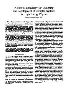
Employee
Registrar
Chief
Document registration Document
Order approval
Order Fig. 2. Class diagram with ridged interface notation.
and the representation method), and ROOM interfaces (in contents and the representation method). In real-time systems, the abstraction of entry and exit points of different software components plays an important role. That is why a port, a special element from ROOM, was added to RTST++. RTST++ provides several ways for port and interface representation. The example shown in Fig. 1 may be represented in an abbreviated form in RTST++ (see Fig. 2). In addition, there is the following variant available: ports are not shown at all, while interfaces are depicted as associations; it is convenient, when objects of a given class may be linked with objects of another class through the given port in only one way.
A software component defined as a class with ports and interfaces may have a finite-automaton behavior, described in terms of the behavior model of RTST++. The behavior model, in turn, can be represented in two alternative notations: based on the STD variant used in ROOM or based on the extended SDL finite automaton. Using the STD notation, it is convenient to define the behavior of the system components on the early stages of the development: numerous minor details may be temporarily excluded from view. At the same time, SDL diagrams make it possible to represent the smallest details of algorithms. This possibility becomes useful at the late stages of the design. The information shown on STD diagrams, may be “loaded” onto SDL diagrams; i.e., the results obtained at the earlier stages will not be lost during the transition to a more formal specification. In the framework of RTST++, STD and SDL notations are used to describe the unified behavior model; thus, the reverse is always possible; i.e., one can load the results of the work with the SDL editor onto an SDL diagram. Such an approach differs from that used in INSYDE [8], where STD diagrams are simply translated into SDL, the reverse translation and the integrity of two of the representations of the same information are not supported. SDL/PLUS [20] has sufficiently affected the RTST++ behavior model: we do not use SDL data types and expressions either. Instead, we use a more flexible strategy of connection with implementation languages [14] rather than a fixed language, as in [20]. CONCLUSION The main characteristic feature of RTST++ is the integration of an information system and real-time system development tools. Now we briefly list the parts of RTST++ which we paid the most attention to: • component software development tools; • finite-automaton approach to the specification of the system behavior; • database (object-oriented and relational) design tools; • connectivity of models and special means to keep them consistent. We note also that the RTST++ tool, which implements the methodology with the same name, will be released in the near future, and everything we spoke about in this paper will be implemented in it. REFERENCES 1. UML semantics, version 1.1, http://www.rational.com/uml, 1977. 2. Selic, B., Gullekson, G., and Ward, P.T., RTST++ Time Object-Oriented Modeling, Wiley, 1994. 3. ITU Recommendation Z.100: Specification and Description Language (SDL-96), Geneva: ITU General Secretariat, 1996.
PROGRAMMING AND COMPUTER SOFTWARE
Vol. 25
No. 5
1999
RTST++: METHODOLOGY AND A CASE TOOL 4. ITU Recommendation Z.120: Message Sequence Chart (MSC-97), Geneva: ITU General Secretariat, 1997. 5. Marca, D.A. and McGowan, C.L., SADT: Structured Analysis and Design Techniques, New York: McGrawHill, 1988. 6. Vendrov, A.M., CASE-tekhnologii. Sovremennye metody i sredstva proektirovaniya informacionnykh sistem (CASE Technology: Modern Methods and Tools for Information System Design), Moscow: Finansy i statistika, 1998. 7. Yourdon, A., Modern Structured Analysis, Prentice Hall, 1989. 8. Wasowski, M., Witaszek, D., Verschaeve, K., Wydaeghe, B., Holz, E., and Jonckers, V., Methodology (the Comlete OMT*). Report 1.4, 1995. 9. Rambaugh, J., Blaha, M., Premerlani, W., Eddy, F., and Lorensen, W., Object-Oriented Modeling and Design, Prentice Hall, 1991. 10. Dolgov, P., Ivanov, A., Koznov, D., Lebedev, A., Murasheva, T., Parfenov, V., and Terekhov, A., ObjectOriented Extension of the RTST Technology, Zapiski seminara kafedry sistemnogo programmirovaniya “CASE-sredstva RTST++” (Proc. System Programming Dept. Seminar on CASE tools of RTST++), St. Petersburg: St. Petersburg Univ., 1998, no. 1, pp. 17–36. 11. Ivanov, A., Koznov, D., and Murasheva, T., RTST++ Behavior Model, Zapiski seminara kafedry sistemnogo programmirovaniya “CASE-sredstva RTST++” (Proc. System Programming Dept. Seminar on CASE tools of RTST++), St. Petersburg: St. Petersburg Univ., 1998, no. 1, pp. 37–49.
PROGRAMMING AND COMPUTER SOFTWARE
Vol. 25
281
12. Parfenov, V.V. and Terekhov., A.N., RTST: A Technology for Technique Programming Embedded Real-Time Systems, Sistemnaya informatika (System Informatics), no. 5: Architectural, Formal, and Programming Models, Novosibirsk, 1997, pp. 228–256. 13. Terekhov, A.N., RTST: A Technology for Programming Embedded Real- Time Systems, Zapiski seminara kafedry sistemnogo programmirovaniya “CASE-sredstva RTST++” (Proc. System Programming Dept. Seminar on CASE tools of RTST++), St. Petersburg: St. Petersburg Univ., 1998, no. 1, pp. 3–17. 14. RTST++ Methodology Notation Reference, Technical Report. www. 15. ITU SDL Methodology Guidelines and Bibliography. Appendix I to Recommendation Z.100, Geneva: ITU General Secretariat. 16. Booch, G., Object-Oriented Analysis and Design with Application, 2nd edition, Benjamin/Cummings, 1994. 17. Andersson, M. and Bergstrand, J., Formalizing Use Cases with Message Sequence Charts, Master thesis, Dept. of Communication Systems, Lund Institute of Technology, EFD LTH, 1995, http://www.efd.lth.se/~d87man/ EXJOBB/ps.html. 18. Toshchev, A., ERwin and automatic client application code generation, Komp’yuter Press Moscow: 1998, no. 10. 19. SDT 3.1, Technical Presentation, Telelogic, 1997. 20. Bardzin’, Ya.M., Kalkin’sh, A.A., Strods, Yu.F., and Sytsko, V.A., Yazyk spetsifikatsii SDL/PLUS i ego primeneniya (The SDL/PLUS Specification Language and Its Applications), Riga: 1998.
No. 5
1999