Email: {rubing, radu, tf}@dps.uibk.ac.at. Abstract. The execution of workflow applications on the Grid is a com- plex issue because of its dynamic and ...
Run-time Optimization for Grid Workflow Applications Rubing Duan, Radu Prodan, Thomas Fahringer Institute of Computer Science, University of Innsbruck Email: {rubing, radu, tf}@dps.uibk.ac.at
Abstract The execution of workflow applications on the Grid is a complex issue because of its dynamic and heterogeneous nature. While the Grid provides good potential for achieving high performance, it also introduces a broad set of unpredictable overheads and possible failures. In this paper we present new methods for scalable and fault tolerant coordination of workflows in dynamic Grid environments, including partitioning, static and dynamic optimization, as well as Virtual Single Execution Environment, incorporated into the ASKALON distributed workflow Enactment Engine. We demonstrate the effectiveness of our methods on a material science workflow application executed in a real-world Grid environment.
1 Introduction Workflows today play a very important role in the scientific and business communities. Grid applications are not monolithic entities anymore, but rather complex workflows that need to be distributed and executed efficiently in a highly heterogeneous and dynamic environment like the Grid which is a challenging problem. Although good workflow scheduling is the foundation of good performance, the dynamic nature of Grid environments opens a great potential for run-time steering, optimization, and fault tolerance. To address these problems, we propose a distributed Enactment Engine for performance-oriented and fault tolerant execution of scientific workflow applications within the ASKALON Grid application development and computing environment [9]. ASKALON gives the user the opportunity to express workflow applications as a set of activities interconnected through control flow and data flow dependencies using two high-level abstractions: a graphical UML modelling tool and an abstract XMLbased specification language. So called composite activities that include sub-workflows and parallel loops allow the user to express large-scale workflows consisting of hundreds to thousands of activities in a compact form. The XML representation of a workflow represents the input to the Enactment Engine that interacts with a Scheduler for appropriate mapping of the workflow activities onto the Grid resources, based on information provided by a Performance Prediction service (using historical data). Based on the hands-on experience with several real-world applications in a real Grid environment, we have identified three major types of performance overheads. (1) The first type is related with the implementation of the individual workflow activities and is essentially independent of distributed nature of the
workflow application (i.e. it is a sequential and parallel processing problem, rather than a Grid problem). For example, we observed that pre-compiled static binaries are often used by scientists as a convenient (but short sighted) way to deploy legacy applications on newly available Grid sites with compatible processors and operating systems but different parallel architectures. (2) The second type of overheads is related to the workflow structure and distributed nature of the Grid application, and includes in principal job submission and file transfer latencies or inappropriate scheduling due to various unpredictable factors such as external load in dynamic Grids or simply inaccurate prediction information used in the mapping process; (3) The third type of overheads is introduced by the ASKALON middleware services to realize their internal functionality and includes fault tolerance (i.e. checkpointing, retry, replication) and online monitoring functionality which we described in [9]. In this paper we aim to devise methods that address and reduce the second type of performance overheads related to the distributed execution workflow applications. The contributions of this paper are both theoretical and experimental. We propose: (1) a distributed service-oriented Enactment Engine with a master-slave architecture for de-centralized coordination of scientific workflows; (2) an algorithm for partitioning a scheduled workflow for distributed coordination among several slave Enactment Engine services; (3) two phase control and data flow optimization process for transforming and simplifying the workflow structure to further reduce its execution cost in geographically distributed Grid environments; (4) a new mechanism and algorithm that significantly simplifies the definition of workflows and reduces the cost of communication for compute intensive scientific workflows with large numbers of small sized data dependencies. The paper is organized as follows. Section 2 overviews the architectural design of the Enactment Engine. Section 3 presents a formal approach to workflow partitioning, followed by several techniques for optimizing workflow executions in Section 4. Section 5 evaluates our methods for a real-world material science application executed in a real Grid environment. Section 6 discusses the related work. Section 7 concludes the paper with a summary and a short discussion of future research.
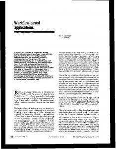
2 Architecture We designed the Enactment Engine using a distributed service-oriented architecture organized in a master-slave communication model which includes three types of services (see Figure 1). (i) One master engine receives the XML representation of the workflow and interacts with the Scheduler for ap-
handles the case of special workflows whose structure is statically unknown or may change during the execution; (iii) Virtual Single Execution Environment Optimizer within the master engine for optimizing special case of scientific workflows characterized by a large set of small data dependencies. In our approach, the run-time optimization of workflow executions is performed in a four phase procedure, as shown in Figure 1. In the first step, the XML-based workflow specification is delivered to the Scheduler for appropriate mapping onto the Grid resources. Once the concrete workflow schedule has been received, the master engine starts partitioning the workflow, followed by the static optimization which transforms and simplifies the workflow for a light-weight execution control with reduced Grid service access latencies and data transfer communication overheads. After all these optimizations have been performed, the master engine sends each partition to a slave engine for execution. During run-time, the workflow execution is dynamically improved by the dynamic optimizer.
3 Workflow Partitioning
Figure 1. Enactment Engine architecture.
The basis for distributed execution of workflows in our approach is the workflow partitioning which needs to be performed such that the communication between the master and the slave engines that coordinate the individual partitions is minimized. Determining the number of partitions of a set of n numbers is a classical problem of combinatorial mathematics called the n-th Bell number, which is an NP-hard problem. Some related partitioning algorithms are proposed to solve this problem, although their algorithms have different goals [1, 8].
propriate mapping onto the available Grid resources. The master engine monitors the execution of the entire workflow and the state of the slave engines. (ii) Several slave engines (usually one for each Grid site) monitor the execution of individual workflow partitions and report to the master whenever individual activities change their state or when the partitions produce some intermediate output data relevant to other partitions or to the overall execution. (iii) If the master engine crashes, a random backup engine (chosen by the master beforehand) becomes the master and immediately selects another backup slave randomly. Such a distributed architecture increases the fault tolerance of the engine and offers improved scalability through decentralized orchestration of large numbers of activities characteristic to scientific workflows. To support run-time optimization of workflow executions in Grid environments, we enhanced the Enactment Engine with the following two additional components.
Definition Let W = (AS, CF D, DF D) denote a workflow application, where AS = {A1 , . . . , An } is the set of activities, CF D = {(Asource δ c Asink ) | Asource , Asink ∈ AS} is © the set d of control flow dependencies, and ª DF D = (Asource δ Asink , Data) | Asource , Asink ∈ AS is the set of data flow dependencies, where Data denotes the I/O data (i.e. parameters or files) to be transferred between the Asource and Asink activities. We define a workflow partition as the largest sub-workflow with the following properties: (1) all activities are scheduled on the same Grid site; (2) there must be no control flow and data flow dependencies to / from activities that have predecessors / successors within the partition.
Workflow Partitioner (see Section 3) resides within the master engine and distributes the workflow into smaller partitions that can be executed more efficiently and with smaller overheads by individual slave engines, usually one for each Grid site. We define a Grid site as a collection of compute units (usually a parallel computer) accessible through access policies established by local administration authorities, usually through a local job queuing system (e.g. see Table 3 in Section 5).
Goal The goal of the partitioning algorithm presented in this section is to generate a partitioned workflow WP = (P SP , CF DP , DF DP ) from a workflow W = (AS, CF D, DF P = {P1 , . . . , Pn } is the Tn D), where P SS n set of partitions ∧ i=1 Pi = φ ∧ i=1 Pi = AS, and n is minimum. We base our partitioning algorithm on graph transformation theory [2] as the formal background to rigourously express it. We define several rules for defining valid workflow partitions that aim to decrease the complexity of the algorithm (to polynomial) and create the set of cooperating workflow partitions. Let (W, R) denote a workflow transformation system, where R denotes the set of graph transformation rules. We approach the workflow partitioning problem using a four step transformation
Workflow Optimizer (see Section 4) performs transformations within workflow partitions, such as grouping of activities to composite activities to reduce the (remote job submission or file transfer) Grid service latencies and optimizing the control and data flow for different types of workflow applications. The workflow optimizer has three components: (i) Static Optimizer simplifies the workflow structure within the master engine before the workflow execution; (ii) Dynamic Optimizer provides support for workflow run-time steering within the slave engine to cope with situations when the execution no longer follows the optimized plan computed by the Scheduler. Additionally, it also 2
sequence: ³ ´ RCF RDF RM 1 RM 2 W =⇒ WCF , W =⇒ WDF =⇒ W 0 =⇒ WP ,
P1
A1:M1 A2:M1 A3:M2
where WCF = (P SCF , CF DCF , DF DCF ), WDF = (P SDF , CF DDF , DF DDF ), W 0 = (P S 0 , CF D0 , DF D0 ), and WP are partition sets generated using different transformation rules that preserve the control and data flow dependencies of the original workflow W .
A4:M2
P2
A6:M2
A4:M2
A11:M3
P6
A12:M3
A7:M3 A8:M3 A9:M3
A3:M2
A10:M3
P3
A1:M1
A2:M1
A8:M3 A9:M3
IF
A5:M2
P1
P4 A7:M3 While
A6:M2
P5 Sequence
A12:M3 A13:M2
A13:M2
P1
A1:M1
R
A2:M1
P2
1. Every activity of the workflow must belong to exactly one partition: ∀ A ∈ AS, ∃ P ∈ P SCF ∧ A ∈ P ∧ A ∈ / P 0 ∧ ∀ P 0 ∈ P SCF − P ;
A4:M2
A2:M1 A3:M2
A10:M3
A5:M2
A11:M3
P6
A12:M3
P7
A13:M2
A4:M2
P2
A7:M3
A8:M3 A9:M3
IF A10:M3
A6:M2
P5
P1
While
A5:M2
P3
(c) Merge two partitions. Composite activity A:M
A1:M1
P4 A7:M3
A6:M2
2. Every partition is one composite or atomic activity. Currently we perform this step by using information provided by the user in the XML-based workflow representation and mapping one composite activity (e.g. parallel activity consisting of a set of independent atomic activities) to one partition;
(b) Data-flow based partition.
A8:M3 A9:M3
P3
A3:M2
P3
A11:M3
P2
(a) Control-flow based partition.
CF Step 1: W =⇒ WCF . Partition the original workflow according to three control flow dependency rules RCF :
A10:M3
A5:M2
A11:M3
P5
A12:M3
P6
A13:M2
P4
(d) Partitioned workflow. Partition
Data and control flow dependency
Activity A scheduled on the Grid site M
Figure 2. Workflow partitioning example.
3. No control flow dependencies between intermediate activities in different partitions are allowed: ∀ A1 ∈ P1 ∈ P SCF ∧ (pred(A1 ) ∈ P1 ∨ succ(A1 ) ∈ P1 ) ∧ (@ (A1 δ c A2 ) ∈ CF DCF ∧ @ (A2 δ c A1 ) ∈ CF DCF , ∀ A2 ∈ P2 ∈ P SCF ), where pred and succ denote the predecessor, respectively the successor of an activity in the workflow;
R
M1 Step 3: (WCF , WDF ) =⇒ W 0 . Merge the two sets P SCF and P SDF of control flow and data flow based partitions computed in Sthe previous two steps into one partition set, as follows: W 0 = ∀P Si ∈P SCF {P Si ∩ P Sj }, while preserving the control
∀P Sj ∈P SDF
and data flow dependencies and the partitioning goals formally described in the beginning. For our example in Figure 2(c) we obtain: P S 0 = {{A1}, {A2}, {A3, . . . , A6}, {A7, . . . , A10}, {A11}, {A12}, {A13}}.
4. The number of activities inside one composite activity must be more than the average processor number on one Grid site. We introduce this rule to avoid too fine-grained partitions in the workflow that would start slave engines on sites with little workload.
R
M2 Step 4: W 0 =⇒ WP . Since the partitioning may have been done too fine grain, we merge the partitions connected through control flow dependencies using the following two merge rules:
For example, in Figure 2(a) we partition all atomic activities of the composite activities IF, While, and Sequence into one partition, respectively, which produces the following control flow partitioning: P SCF = {{A1}, {A2}, {A3, . . . , A6}, {A7, . . . , A10}, {A11}, {A12, A13}}.
1. Merge the partitions that are connected through control flow dependencies but have no data flow dependencies (i.e. they are scheduled on the same site): [ P SP = {{Pi ∪Pj }−{Pi }−{Pj } | ∀ A1 ∈ Pi
R
DF Step 2: W =⇒ WDF . Partition the original workflow according to three data flow dependency rules RDF :
∀ Pi 6=Pj ∈W 0
∧ ∀ A2 ∈ Pj ∧ @ (A1 δ d A2 ) ∈ DF D ∧ (Pi δ c Pj ) ∈ CF D0 };
1. Each activity of the workflow must belong to exactly one partition: ∀ A ∈ AS, ∃ P ∈ P SDF ∧ A ∈ P ∧ A ∈ / P 0 , ∀ P 0 ∈ P SDF − P ;
2. In the final partition, there must be no control and data flow dependencies to / from activities that have predecessors / successors within the partitions. This is achieved by iteratively applying the following formula within fixed point algorithm until nothing changes anymore and the largest partitions are achieved: [ P SP = {{Pi ∪ Pj } − {Pi } − {Pj } |
2. Eliminate the data dependencies between activities scheduled on the same Grid site: DF DDF = DF D − (A1 δ d A2 , Data), ∀ A1 , A2 ∈ AS ∧ schedule(A1 ) = schedule(A2 ); 3. Activities scheduled on the same Grid site belong to the same partition: ∀ A1 ∈ P ∈ WDF ∧ ∀ A2 ∈ P ∧ schedule(A1 ) = schedule(A2 ).
∀ Pi 6=Pj ∈W 0
¬(Pi δ d Pj ∈ DF D0 ) ∧ (Pi δ c Pj ∈ CF D0 ) ∧ ((@ Px 6= Pj ∈ W 0 | (Pi δ c Px ∈ CF D0 )) ∧
Figure 2(b) displays the result of the data flow partitioning according to the schedule of the activities: P SDF = {{A1, A2}, {A3, . . . , A6, A13}, {A7, . . . , A11, A12}}.
(@ Px 6= Pi ∈ W 0 | (Px δ c Pj ∈ CF D0 )))}. 3
Therefore, P SP = {{A1}, {A2}, {A3, . . . , A6}, {A7, . . . , A11}, {A12}, {A13}}. The partitioning of a workflow helps the slave engines execute the workflow partitions independently with little asynchronous communication among themselves. The partitioning of the workflow also contributes to the reduction of the latency and coordination overheads of large numbers of activities characteristic to our scientific workflows.
A1
A2
An
A1
A2
An
B1
B2
Bn
B1
B2
Bn
CP1
Parallel
CP2
Parallel
Parallel
(c) control flow optimized workflow
(b) control flow optimization analysis
(a) original workflow
CPn
Figure 3. Static control flow optimization.
4 Workflow Optimization A1
The workflow optimizer focuses on further simplifying the sub-workflows produced in the partitioning phase to achieve an easier and faster execution on the Grid. There are two phases in the optimization process: static optimization performed by the master engine before sending the partitions to the slave engines, and dynamic optimization performed by the slave engines during the execution of a workflow.
4.1
A2
A3
An
A1
A2
A3
An-1 An
An-2
P1
Parallel
Pk Parallel
B
A1
A2
B
A3
P1:M1
Static Optimization
A4
A5
Pb
An-2
A6
P2:M2
An-1 An Pk:Mk
Archive
Archive
Parallel
According to our previous experiences [9], one remote job submission to a Grid site with a batch queuing system has about 10−20 seconds of overhead mainly due to mutual authentication latency and polling for status change. This overhead may be significantly larger if the access to Grid sites is performed through batch queuing systems and becomes critical for large workflows comprising hundreds to thousands of activities like in the case of our real-world workflows. Similarly, the (GridFTP) file transfer latency is of about one second which is rather critical for the large numbers of small files that are produced by our applications. The objective of the static optimization is simplify and reduce the workflow structure and size by merging atomic activities and data dependencies that reduces the Grid latencies and other sources of execution overheads.
Pb:M1 P:M
Partition P scheduled on the Grid site M Data flow dependency
Composite activity
Figure 4. Static data flow optimization.
which groups activities Ai and Bi in one single composite activity that simplifies the workflow and, therefore, reduces the job submission latencies to half in this particular example (see Figure 3(c)).
4.1.1 Static Control Flow Optimization
4.1.2 Static Data Flow Optimization
This optimization step aims to wrap the atomic activities defined by the user into composite activities that can be executed as one single remote job submission on a Grid site, which reduces the overall latency and also decreases the complexity of large workflows. The static workflow optimizer receives a workflow partition P and performs a transformation that produces a new partition CP that merges the activities linked through control flow dependencies but with no run-time data dependencies (i.e. since they are scheduled on the same Grid site) into composite activities are executed as an atomic unit of work (i.e. remote GRAM job submission): CP = {CP1 , . . . , CPn }, where CPi = {A} ∨ (∀ A1 ∈ CPi , ∃ A2 ∈ CPi ∧ ((A1 δ c A2 ) ∈ CF DP ) ∨ (A2 δ c A1 ) ∈ CF DP ) ∧ @ A3 ∈ CPi ∧ ((A1 δ d A3 ) ∈ DF DP ∨ (A3 δ d A1 ) ∈ DF DP )}, ∀ i ∈ [1, n]. Figure 3(a) illustrates one typical static control flow optimization in a workflow consisting of activities A1 , . . . , An and B1 , . . . , Bn , where Ai and Bi are linked through a direct control flow dependency and have been scheduled to the same Grid site, which means that any eventual data dependency has been eliminated in the second step of the partitioning algorithm. Figure 3(b) displays the analysis of the control flow optimization,
After the optimization of the control flow, the static data flow optimizer reorganizes first the input and output ports of the partitions and composite activities. Thereafter, it analyzes the data dependencies between all activities, groups them according to all dependencies involving the same source and destination Grid sites, and generates a file transfer activity of a single compressed archive whenever the source and destination sites are S different: DF S DP = ∀P1 ,P2 ∈P SP {(P1 , P2 , Archive)}, where Archive = ∀(A1 ,A2,Data)∈DF D∧A1 ∈P1 ∧A2 ∈P2 {Data} is a compressed archive of all data dependencies between partitions P1 and P2 (typically instantiated during execution by files). Figure 4(a) presents a typical example in which activity B collects data from a large number of parallel activities A1 , . . . , An . First of all, the data flow analysis packs the data output ports of all activities belonging to the same partition (i.e. scheduled on the same site – see Figure 4(b)). Afterwards, one single (GridFTP-based) file transfer activity is generated between the partitions that are scheduled on different sites which reduces the number of file transfers from n to one in this example (see Figure 4(c)). 4
4.2
Dynamic Optimization
There may occur many external factors during the execution of large workflows in dynamic Grid environments that no longer follows the plan computed by the Scheduler. Such unpredictable factors may include unexpected queueing times, external load on processors (e.g. on Grid sites that also serve as student workstation labs in our real Grid environment – see Section 5), unpredictable availability of processors on workstation networks (e.g. if a student shuts down a workstation or reboots it to Windows mode), jobs belonging to other users on parallel machines, congested networks, or simply inaccurate prediction information. Moreover, we often encountered in our real Grid environment sites that offer a limited capacity for certain resources, for example small number of I/O nodes that only allow a limited number of concurrent file transfers, otherwise generate a denial of service attack. The dynamic optimizer handles the run-time steering of the workflow execution and aims to minimize the losses due to such unpredictable factors that violate the optimized static mapping computed by the Scheduler. The scientific workflows that we use to validate our work are typically characterized by a large number of independent activities to be executed in parallel, which we model in XML as a composite activity using a parallel loop syntax. Moreover, such workflows can have a dynamic structure which is known only at run-time, for example the number of activities to be executed in parallel may depend on the value taken by some output port of a predecessor activity (see Section 5 for a real world example). The dynamic optimizer handles this situation by building the new shape of the workflow as soon as it is known and sending it back to the Scheduler for a new optimized mapping onto the Grid. In addition, executing such large numbers of parallel activities in dynamic Grid environments often produces a load imbalance (for example due to some unexpected external jobs submitted to the queue) that leaves some of the Grid sites idle, while others are overloaded with activities waiting in the queue. To handle this situation, the Enactment Engine regularly checks the load of available Grid sites based on the number of activities queued and, if an uneven distribution is detected (using execution time information provided by the Performance Prediction service), it selects some of the queued activities for migration and replicates them to the less loaded sites (e.g. with free processors). Additionally, the engine must also replicate the necessary input files as part of a data flow optimization process.
4.3
(a) Partitioned workflow and original data flow.
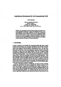
Figure 5. VSEE example. where the latency for mutual authentication to the GridFTP server (orders of seconds) clearly dominates the communication time if n is large. To handle this case, we propose a data flow optimization called Virtual Single Execution Environment (VSEE) which replaces the data dependencies between activities with the full I/O data environment, defined for a partition P as follows: [ [ VP = VP 0 {Data}. ∀(P 0 ,P,Data)∈DF DP
∀(P,P 00 ,Data)∈DF DP
Clearly, the following property holds: ∃ (P 0 , P, Data) ∈ DF DP ⇐⇒ VP 0 ⊂ VP . Another benefit of using VSEE is the fact that specifying lots of data input and output ports for activities are painful and error prone. With this technique, users can assume that activities have one single aggregated data dependency to their predecessors, which eliminates the need to specify all fine grained logical data ports explicitly. This shields the user from the complexity of the workflow definition and it gives scientists a more friendly interface to the Grid. The VSEE mechanism can also reduce the overhead of activity migration defined in the dynamic optimization process as we will show in Section 5. Upon executing a workflow partition on a Grid site, each slave engine automatically creates and removes one working directory that represents its execution environment. The VSEE mechanism transforms the complex data dependencies between activities to one environment dependency between partitions. At run-time, the engine packs the data environment which can be transferred by one single file transfer. VSEE, therefore, noticeably reduces the latency and the number of intermediate data transfers for compute intensive Grid applications that have large amounts of small sized data dependencies. Figure 5 illustrates one real world workflow (that we also use for the experiments in Section 5) to be executed on three Grid sites {M1 , M2 , M3 }. First of all, the workflow is split into seven partitions P SP = {P1 , . . . , P7 } (see Figure 5(a)) based on the algorithm presented in Section 3. Thereafter, the data flow between partitions is optimized according to the VSEE-based relationships depicted in Table 1. For example, transferring data between partitions only according to the data flow dependencies requires P6 receive the data from Vin ∪ V1 ∪ V2 ∪ V3 ∪ V4 = V4 , since Vin ⊂ V1 ⊂ V2 ⊂ V3 ⊂ V4 . Table 2 displays the final
Virtual Single Execution Environment
Certain scientific workflow applications are characterized by a large (hundreds to thousands) number of activities with complex data dependencies instantiated by a large number (hundreds to thousands) of small files (several kilobytes each). In such cases, the overhead of communication is dominated by latencies for sending individual small files where the effective data transfer is small. This effect can be easily grasped through a commonly used analytical formula that models the predicted communication time Tcomm for sending n files of aggregated size size: Tcomm = n ∗ Latency +
(b) VSEE optimized data flow.
size , Bandwidth 5
result of this VSEE data flow optimization process automatically performed by the Enactment Engine. RV
V1
V2
V3
V4
V5
V6
Vin V1 V2 V3 V4 V5 V6 V7
⊂ –
⊂ ⊂ –
⊂ ⊂
⊂ ⊂ ⊂ ⊂ –
⊂ ⊂ ⊂ ⊂ ⊂ –
⊂ ⊂ ⊂ ⊂ ⊂
–
– ⊂
V7
After lapw0 completes, the dynamic optimizer reads an lapw0 output port that indicates the number of subsequent parallel k-points, builds the complete shape of the workflow, and sends the full workflow back to the Scheduler for optimized mapping onto the Grid. We use a variation of the Heterogeneous Earliest Finish Time algorithm [13] to map the workflow activities onto the Grid sites, which proved to be the most efficient heuristic for this application in previous experiments [9] conducted in a static Grid environment (i.e. no external load) using accurate prediction information obtained from previous training runs. After receiving the full workflow schedule, the Enactment Engine can start partitioning the workflow. We chose for our experiments a WIEN2k problem size that produces 250 parallel k-points at run-time, which means a total of over 500 workflow activities. We executed this application on a subset testbed of a national Grid infrastructure [6] consisting of a set of parallel computers and workstation networks accessible through the Globus toolkit and local job queuing systems as separate Grid sites. We first executed the workflow application on the fastest site available (i.e. altix1.jku in Linz) that gives the indication of what can be achieved for this application by using only local compute resources. Then we incrementally added the next fastest sites for this application, as indicated by the rank column in Table 3, and observed the benefits or losses obtained by executing the same problem size in a larger Grid environment.
Vout
⊂
⊂ ⊂ ⊂ –
⊃
Table 1. VSEE relationships.
Transfer
P1
Vin V1 V2 V3 V4 V5 V6 V7
X
P2
P3
P4
P5
P6
X
X
P7
Output
X X X X
X
Table 2. Minimum VSEE transfer set. For certain compute intensive applications characterized by large numbers of small data dependencies, the VSEE mechanism can drastically decrease the number of file transfers up to several orders of magnitude, while increasing the data size by several factors. Considering fixed latencies of about about 1 second for every individual file transfer and the improved bandwidth utilization for transferring large data archives, this mechanism can significantly improve the communication time in scientific workflows as we will illustrate in Section 5.
Rank
Site
#
CPU, GHz
Manager
Location
1 2 3 4 5 6
altix1.jku altix1.uibk schafberg agrid1 arch 19 arch 21
16 16 16 16 20 20
Itanium 2, 1.6 Itanium 2, 1.6 Itanium 2, 1.6 Pentium 4, 1.8 Pentium 4, 1.8 Pentium 4, 1.8
Fork Fork Fork PBS PBS PBS
Linz Innsbruck Salzburg Innsbruck Innsbruck Innsbruck
Table 3. The Austrian Grid testbed. First, Figure 6(a) presents the number of WIEN2k partitions computed by the partitioning algorithm for each Grid site configuration. The number of partitions depends on the workflow structure and the execution plan computed by the Scheduler and is proportional with the number of sites. Figure 6(b) shows the execution times for running the same WIEN2k problem on different Grid size configurations ranging from one to six aggregated sites. Similarly, Figure 6(c) displays the Grid speedup computed as the ratio between execution time on multiple distributed sites and the execution time on the fastest local site available (altix1.jku in Linz). First of all, without any optimization the performance and the speedup decrease with the increase in the number of Grid sites used for scheduling and running the workflow. With static and dynamic optimization, the WIEN2k execution time improves because of the simplified data flow and balanced execution of the lapw1 and lapw2 parallel activities. We exhibit a slow down from five to six Grid sites using static optimization because of the increased communication time across six distributed sites. Figures 6(d) and 6(e) show that the number of file transfers, respectively remote job submissions, are considerably reduced when optimization is applied which explains the performance results obtained. Figure 6(f) displays the average GridFTP and GRAM latencies (i.e. measured for each job from the submission time until it becomes active) experienced in our runs, which ranges from one to 18 seconds when a queuing system is used
5 Experiments In this section, we evaluate our proposed methods using a real world scientific workflow application executed in a national Grid infrastructure. WIEN2k1 is a program package for performing electronic structure calculations of solids using density functional theory based on the full-potential (linearized) augmented plane-wave ((L)APW) and local orbital (lo) method. We have ported the application onto the Grid by splitting the monolithic code into several course-grain activities coordinated in a workflow, as already illustrated in Figure 5(a). The lapw1 and lapw2 activities can be solved in parallel by a fixed number of so-called k-points. A final activity converged applied on several output files tests whether the problem convergence criterion is fulfilled. The number of recursive loops is statically unknown. One peculiarity of this workflow is that the number of parallel lapw1 and lapw2 activities is unknown until the first activity lapw0 completes its execution. Since this number is statically unknown, the Enactment Engine assumes one serial activity in each case and performs no partitioning since the workflow only has a total of nine serialized activities that the Scheduler maps onto the same Grid site. 1 http://www.wien2k.at/
6
12 10 8 6 4 2
5000 4500 4000 3500 3000 2500 2000 1500 1000 500 0
6 5
1
2
3 4 5 Number of Grid sites
6
2000 1500 1000 500 0 5
Load Imbalance Time [s]
Data size [MB]
Without optimization Static optimization
80 60 40 20 0 5
300 200 100
Dynamic&static optimization
(g) Size of transferred files.
VSEE
6
Dynamic&static optimization VSEE
14 12 10 8 6 4 2
0
0
2 3 4 Number of Grid sites
5
altix1.jku
6
altix1
schafberg
agrid1
arch_19
arch_21
Grid site
Static optimization
GridFTP
GRAM (Fork)
GRAM (PBS)
(f) Latency of GridFTP and GRAM. 200
900 800 700 600 500 400 300 200 100 0
180 160 140 120 100 80 60 40 20 0
1
6
5
(c) Speedup.
(e) Number of job submissions.
100
Without optimization
Static optimization VSEE
400
Without optimization
120
4
18
1
Static optimization VSEE
4
3
16
6
140
3
2
Number of Grid sites
Migration Time [s]
4
Number of Grid sites
1
6
500
(d) Number of file transfers.
2
Number of Grid sites
5
600
Number of Grid sites
1
4
Latency time [s]
Number of job submission
Number of files
2500
Without optimization Dynamic&static optimization
3
(b) Execution time.
3000
3
2
Without optimization Dynamic&static optimization
3500
2
2
0
(a) Number of partitions.
1
3
1
1
0
4
Speedup
14
Execution Time [s]
Number of Partitions
16
2 3 4 Number of Grid sites
Without optimization
5
6
Dynamic optimization
(h) Overhead of load imbalance.
lapw0
lapw1
lapw2FERMI
WIEN2K activities Without VSEE
lapw2
VSEE
(i) Overhead of activity migration.
Figure 6. WIEN2k experimental results.
6 Related work
underneath. Figure 6(g) shows that the size of transferred data under VSEE is obviously larger than in the other cases, however, VSEE offers the biggest execution improvement since it reduces the number of file transfers by three orders of magnitude that drastically reduces the latencies (i.e. mutual authentication to the GridFTP service). The improvement of dynamic optimization is due to several external jobs that we submitted to the fastest Grid site which caused several lapw1 and lapw2 activities wait in the queue. The consequence is an increased load imbalance in the execution of the lapw1 and lapw2 parallel activities, which is reduced to half by dynamic optimization as shown in Figure 6(h). Figure 6(i) compares the data transfer overheads of the activity migration upon dynamic control flow optimization with and without the VSEE mechanism. One important aspect is that the data transfer overhead upon migrating a lapw1 and lapw2 activity is zero when using the VSEE mechanism. The reason is that the sequential activities lapw0 and lapw2 fermi replicate all their output to the sites where the following lapw1 and lapw2 parallel activities are scheduled. Therefore, these activities will find their inputs already prepared on the sites where they are migrated which eliminates the data transfer overhead.
The idea of distributed execution was pioneered by the INCAS [1] prototype which partitioned the workflow into independent subsets that are distributed to the nodes where execution may take place. Other research in performance-oriented distributed computing focused on partitioning algorithms for systemlevel load balancing or task scheduling [5] that aims to maximize the overall throughput or average response time of the system. The idea, however, was not yet evolved to the Grid computing field. The Pegasus system [8] uses DAGMan as enactment engine enhanced with data derivation techniques that simplifies the workflow at run-time based on data availability. Pegasus provides a workflow partitioning approach which concentrates on different phases of the execution before the scheduling takes place. Our research, in contrast, focuses on how to partition the workflow after the scheduling phase and coordinate its execution in a decentralized environment, as opposed to the centralized approach of DAGMan. Kennedy et al. [11] compared several task-based and workflow-based approaches to resource allocation for workflow 7
application based on simulation rather than real executions as in our case. They conclude that workflow-based approaches perform better for data intensive cases while task-based approaches are suited for compute intensive workflows. In this paper we present a new mechanism called VSEE suited for compute intensive workflows with large amounts of small data dependencies. Kennedy et al. also study the impact of uncertainty to the overall workflow schedule, but do not propose run-time optimization techniques as done in this paper. Taylor et al. [10] use the Grid Application Toolkit interface to access Grid services through JXTA and Web services. Triana has a distributed engine to distribute sections of a workflow to remote machines. The user has to understand the Grid and the workflow execution, while our approach partitions and distributes the workflow automatically. UNICORE [7] provides manual scheduling support by allowing the user to allocate resources and specify data transfers task though a graphical user interface. Our engine can automatically map the data between its source and sink, and optimize the data movement. Taverna [12] in my Grid follows a service-oriented Grid architecture which use Freefluo enactor as the execution engine. Taverna focuses on data integration for bio-informatics, fault tolerance, and user-friendly interfaces for biologists. The Enactment Engine and ASKALON target more generic scientific workflows and are not designed for specific domains. The GrADS [3] project aims to achieve high performance in Grid environments through dynamic adaptation and performance contract monitoring that tailors a configurable object program and defers the code generation to the target run-time environment. The work primarily focuses on Grid support for numerical libraries and parallel MPI applications. The workflow management in Gridbus [4] is driven by Grid economy requirements, which emphasizes on the use of marketbased principles and algorithms. Our work, in contrast, concentrates on performance-driven scientific workflow applications. None of these projects provide support for scientific workflows with dynamic control and data flow structure (statically unknown before the execution) that may change at run-time based on the computations performed by certain activities.
change their graph-based structure at run-time and eliminates eventual load imbalance by using idle and redundant resources during executions that do not follow the original plan computed by the Scheduler. In addition, we proposed a new optimization approach called VSEE that replaces large numbers of data dependencies between individual activities with the entire I/O data environment that significantly reduces data transfer complexity of compute intensive workflow applications. We have validated our methods for a real world material science workflow application consisting of over 500 activities executed in a national Grid testbed consisting of 104 processors geographically distributed on six sites. In the future, we plan to investigate more algorithms for partitioning and optimization of workflows for other real world workflows from the astrophysics and meteorological fields.
References [1] D. Barbara, S. Mehrotra, and M. Rusinkiewicz. Incas: A computation model for dynamic workflows in autonomous distributed environments. Technical report, May 1994. [2] L. Baresi and R. Heckel. Tutorial introduction to graph transformation: A software engineering perspective. In Proceedings of the First International Conference on Graph Transformation (ICGT 2002)., page 402C429. Springer-Verlag, 2002. [3] Francine Berman, et al. The GrADS Project: Software support for high-level Grid application development. The International Journal of High Performance Computing Applications, 15(4):327–344, 2001. [4] Rajkumar Buyya and Srikumar Venugopal. The gridbus toolkit for service oriented grid and utility computing: An overview and status report. In 1st International Workshop on Grid Economics and Business Models (GECON 2004), pages 19–36. IEEE Computer Society Press, April 2004. [5] S. Chandra and M. Parashar. Towards autonomic applicationsensitive partitioning for samr applications. Journal of Parallel and Distributed Computing, 65(4):519–531, 2005. [6] The Austrian Grid Consortium. http://www.austriangrid.at. [7] Dietmar W. Erwin and David F. Snelling. UNICORE: A Grid computing environment. Lecture Notes in Computer Science, 2150:825–??, 2001.
7 Conclusions and future work
[8] Ewa Deelman et. al. Mapping abstract complex workflows onto grid environments. Journal of Grid Computing, 1:25–39, 2003.
Executing workflow applications in dynamic Grid environments needs run-time optimization and steering techniques for achieving good performance. In this paper we described the distributed Enactment Engine of the ASKALON application development and computing environment. We proposed a partitioning algorithm for distributing a workflow application that offers improved fault tolerance and lower coordination overheads through a distributed master-slave service-oriented architecture. The engine improves the execution of large-scale workflows on multiple geographically distributed Grid sites through two run-time optimization phases. The static optimization simplifies the workflow structure before the execution by archiving and compressing multiple files and merging multiple atomic activities scheduled on the same site, which significantly reduces the huge service latencies exhibited in Grid environments (e.g. authentication latencies to GRAM and GridFTP services). The dynamic optimization handles peculiar scientific workflows that dynamically
[9] T. Fahringer, R. Prodan, R. Duan, et al. ASKALON: A Grid Application Development and Computing Environment. In 6th International Workshop on Grid Computing (Grid 2005), Seattle, USA, November 2005. IEEE Computer Society Press. [10] I.Taylor, M.Shields, I.Wang, and R.Rana. Triana applications within Grid computing and peer to peer environments. Journal of Grid Computing, 1(2):199–217, 2003. [11] K.Kennedy, et al. Task scheduling strategies for workflow-based applications in grids. In Proceedings of IEEE International Symposium on Cluster Computing and the Grid 2005 (CCGrid 2005), Cardiff, UK, May 2005. IEEE Computer Society Press. [12] T. Oinn,et al. Taverna: a tool for the composition and enactment of bioinformatics workflows. Bioinformatics, 20(17):3045–3054, 2004. [13] H.Zhao and R.Sakellariou. An experimental investigation into the rank function of the heterogeneous earliest finish time scheduling algorithm. In Euro-Par, pages 189–194, 2003.
8