International Journal of Computing & Information Sciences
108
Vol. 2, No. 2, August 2004
Running Multicast Applications Using Reconfigurable Parallel System Buhari and Hamid R. Arabnia Pages 108 - 113
Running Multicast Applications Using Reconfigurable Parallel System Buhari1, Hamid R. Arabnia2 1 King Fahd University of Petroleum and Minerals, Dhahran, Saudi Arabia 2 The University of Georgia, Georgia, Athens, USA. Emails:
[email protected],
[email protected] Abstract: In this paper we address the important problem of Multicasting using a reconfigurable network topology called the Multi-Ring network. The Multi-Ring network is shown to have a rich set of nice properties that support applications in medical imaging, scientific computing, and artificial intelligence. The most important property of the Multi-Ring topology is “scalability”. It is feasible and cost-effective to interconnect hundreds of thousands of computing notes using the Multi-Ring network topology. Efficient Multicasting operation on a platform composed of thousands of computing nodes is a challenge that is being addressed in this paper. Keywords: Reconfigurable parallel system, multicast application. Received: December 31, 2004 | Revised: April 15, 2005 | Accepted: June 1, 2005
Server
1. Introduction to Multicasting Today’s campus networks support intranet applications that operate between one sender and one receiver. In the emerging campus network, a demand is there for intranet and multimedia applications where one sender will transmit to a group of receivers simultaneously. Applications like these include transmitting all-hands messages to employees, video and audio broadcasting, interactive video distance learning, transmitting data from a centralized data warehouse to multiple departments, communication of stock quotes to brokers, and collaborative computing. With the advent of MP3s, streaming video, MPEGs, voice, and other cutting edge multimedia applications, the toll on the network infrastructure has never been greater. Reaping the benefits of these applications and integrating them into the campus network can be a challenge. High bandwidth use is the order of the day. The capability of today’s networks to combine the text, graphics, audio, and video components and effectively deliver them is increasingly difficult. The most efficient solution for transmitting multimedia is one in which a multimedia server sends one copy of each packet, addressing each packet to a special multicast address. Unlike the unicast environment, a multicast server sends out a single data stream to multiple clients. Unlike the broadcast environment, the client device decides whether to listen to the multicast address or not. Multicasting saves bandwidth and controls network traffic by forcing the network to replicate packets only when necessary. By eliminating traffic redundancy, multicasting reduces network and host processing. A multicast example or grouping is shown in Figure 1.
Multicast Group A
Multicast Group B
Figure 1. Multicast grouping
2. Characteristics of IP Multicasting 1. Facilitates transmission of an IP datagram to a multicast group comprised of zero or more hosts identified by a single IP destination address. 2. Delivers a multicast datagram to all members of the multicast group with the same “best effort” reliability as regular unicast IP datagrams. 3. Supports dynamic membership of a multicast group. 4. Supports all multicast groups regardless of the location or number of members. 5. Supports the membership of a single host in one or more multicast groups. 6. Upholds multiple data streams at the application level for a single group address.
109
International Journal of Computing & Information Sciences
7. Supports a single group address for multiple applications on a host.
3. Internet Group Management Protocol (IGMP) The Internet Group Management Protocol (IGMP) provides means to report their multicast group membership with neighboring multicast routers. IGMP manages multicast traffic throughout networks through the use of special multicast queriers and hosts. A querier is a network device, such as a router, that sends IGMP queries. A set of queriers and hosts that receive multicast data streams from the same source is called a multicast group. Queriers and hosts use IGMP messages to join and leave multicast groups. There are two versions of IGMP: IGMPv1 & IGMPv2. Like IGMPv1, IGMPv2 hosts joining a group do not have to wait for a query to join. When a host wants to join a multicast group, the host sends a host membership report to the multicast group address. IGMPv2 defines a procedure for election of the multicast querier for each network segment [Figure 2]. In IGMPv2, the multicast router with the lowest IP address on the LAN segment is elected as the multicast querier. Initially, every router on the segment believes itself to be the querier for every one of the router’s interfaces that are multicast-enabled. When a router is first multicast-enabled, the router begins transmitting query messages. If the router subsequently detects a queried message that is sourced from a numerically lower IP address, the router ceases to act as a querier on that interface [1]. Lowest IP address = Querier 192.168.2.1
Nonqueriers 192.168.2.2
192.168.2.3
Vol. 2, No. 2, August 2004
4. Connecting members of Multicast Group For efficient transmission of multicast traffic, designated routers construct a tree that connects all members of an IP multicast group. A distribution tree specifies a unique forwarding path between the subnet of the source and each subnet containing members of the multicast group. A distribution tree has just enough connectivity so that there is only one loop-free path between every pair of routers. There are two basic tree construction techniques: sourcespecific trees and shared, or center-specific trees.
4.1. Source-Specific Distribution Trees Source-specific distribution trees require finding a shortest path from the sender to each receiver, resulting in multiple minimal delay trees for a group [Figure 3]. The source-specific method builds a Spanning Tree for each potential source, or subnetwork. These Spanning Trees result in sourcebased delivery trees emanating from the subnetworks directly connected to the source stations. Because many potential sources for a group exist, a different delivery tree is constructed, rooted at each active source. Source-based trees are constructed using a technique called Reverse Path Forwarding (RPF) [1]. If a packet arrives on a link that the local router believes to be on the shortest path back towards the source of the packet, the router forwards the packet on all interfaces except the incoming interface. If the packet does not arrive on the interface that is on the shortest path back towards the source, the packet is discarded. The interface over which the router expects to receive multicast packets from a particular source is referred to as the parent link. The outbound links over which the router forwards the multicast packet are called the child links for this source. Server
Query
Query
Query
Figure 2. IGMPv2 Querier
A Leave Group message was also added in IGMPv2. Whenever any end station wants to leave a group, the host transmits a Leave Group message to the allrouters group (224.0.0.2) with the group field indicating the group that it is going to leave. This transmission allows end systems to tell the router that the hosts are leaving the group.
Figure 3. Source-specific distribution trees
110
Running Multicast Applications Using Reconfigurable Parallel System
4.2. Shared Distribution Trees The shared tree makes use of distribution centers and constructs a single multicast tree, resulting in a low overhead method but sacrificing minimal end-to-end delay [Figure 4]. Unlike source, or shortest path, tree algorithms that build a source-based tree for each source or each (source, group) pair, shared-tree algorithms construct a single delivery tree shared by all members of a group. The shared-tree approach is quite similar to the Spanning-Tree Algorithm except that the shared tree allows the definition of a different shared tree for each group.
Server
Figure 4. Shared distribution tree
5. Implementation using reconfigurable multi-ring: Few criteria are to be considered while implementing reconfigurable systems. They are [4, 5]: a. The connectivity in the network should have certain limits irrespective of the size of the network. b. We should maintain low network diameter due to network reconfiguration. c. The hardware should be of reasonable complexity. In the case of source-specific distribution tree, the grouping of nodes in the tree is made in the form of one ring of eight processors or two rings of four processors or four rings of two processors. These connections are made as per the need of the sourcespecific distribution trees, refer section 4.1. The procedure used to form this multicast tree is just the reverse of the broadcast formation concept. Initially, all the nodes of the multicast tree are joined to form the physical connections, with one and two and four rings [similar to fully connected network]. Then, when a node receives a packet it broadcasts the packet to all other connections [except the source link] so as to enable the packet to reach various destinations. The Routing Information Field (RIF) stores the nodes the packet passes by, while the packet travels from one source towards the destination. The destination tends to receive many packets due to broadcasting of packets by the source
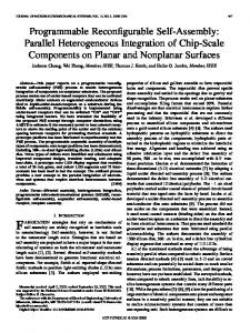
& other intermediate nodes. The destination gets the route information from the RIF field and sends the packet [the first received packet] back along the route specified in the RIF. This route is now used by the intermediate nodes to send the packet back to the source. All the nodes would have learned the specified source tree and the un-needed rings for the specific source is ignored or pruned from the specific source. One of the notable drawbacks of this is that if the route of the first received packet is not the best route, then it might hinder further progress of the setup even after the network has setup the ring according to that route. To consider this problem, the setup of the route for each group is done one after the other. But previously learned routes are made known to the next process that learns for other source-oriented trees so that the impact on the utilization of the route [by previous process] is approximately known. If many multicast groups use a single path, then the utilization of this path might increase. This might become a possible cause of collision or congestion. To avoid this problem from being happening, the previously learnt routes are made known to next processor. Let us consider an example and discuss how multiring network [2] is used in the case of forming multicast groups. The whole network is initially combined with all rings [2, 4, etc]. Then, we need to use the needed links to form multicast groups. Here, as we need to connect P0, P2, P4 and P6 nodes [Figure 5] that are actually connected directly using rings that connect four processors. Hence, we can use that to connect them. This helps us to avoid connecting or using other rings. In order to avoid looping, we don’t connect the link that is of lower bandwidth or longer distance. P0, P2, P4 and P6 form Multicast group
P1
P0
P2
P3
P7
P6
P4
P5
Figure 5. Grouping with a ring of four processors [6]
Let us consider another example and discuss how multi-ring network is used in the case of forming multicast groups. The whole network is initially combined with all rings [2, 4, etc]. Then, we need to use the needed links to form multicast groups. Here,
111
International Journal of Computing & Information Sciences
as we need to connect P0, P1, P2, P6 and P7 nodes [Figure 6]. As there is no direct connection that exists between all these mentioned nodes [P1, P2, P6 and P7], we need to use the single ring that connects all the nodes. In general, we will try to connect all the members of the multicast group with rings that connects less number of processors. If it were not possible as in this case, we would opt for other options like usually a ring partially. P0, P1, P2, P6 and P7 form Multicast group
P1
P0
P7
P2
Vol. 2, No. 2, August 2004
In the case of implementing IGMP on the multi-ring network, the queries are sent in the mode of broadcast, which is implemented when the whole ring is intact. Then, after the replies arrive for the first time, the ring is organized as per the grouping needed.
6. Analysis In order to discuss about the use of multi-ring networks for multicast operation, we analyse our system using a similar procedure as given in [3]. We consider the following variables to determine the various situations in multi-ring analysis.
P6
……… (1)
P3
P4
P5
….(2) Figure 6. Grouping with a ring of eight processors
In the example given in Figure 7, it could be noted that no single ring can help connect all the multicast members. In these kinds of problems, we need to opt to use more than one ring and utilize the connections as much as possible and connect them.
….(3)
……..(4)
P0, P1, P5 and P3 form Multicast group
….(5) P1
P0
P7
Before ring formation, the following two conditions apply: P2
P6
1. For a node in all rings R
P3
P4
P5
Figure 7. Grouping with different rings
The main drawback of slowing or organizing the learning process one-by-one due to the impact of one route over the other is solved using the shared-tree concept. Here, other members of the group use the learned results of one route. Here, similar to sourcespecific tree, the initial setup of multi-ring is to group all the nodes with varying rings. But the major difference is that once a route is learnt, the other routes are pruned for all the members of that group. This group pruning is setup at the switches level to avoid further broadcast overheads.
∑y k =1
ki
=R
∀i ∈ N ;
…………….. (6)
N → List of nodes in the network R → List of rings in the network 2. For a node that is present in only one ring,
R
∑y k =1
ki
=1
∀i ∈ N ; …………….……(7)
N → List of nodes in the network R → List of rings in the network 3. Each ring contains not more than m nodes.
International Journal of Computing & Information Sciences
Vol. 2, No. 2, August 2004
112
Running Multicast Applications Using Reconfigurable Parallel System Buhari and Hamid R. Arabnia Pages 108 - 113
R
∑y k =1
ki
≤m
∀i ∈ N
[2]
Hamid R. Arabnia, Thiab R.Taha, “A parallel numerical algorithm on a reconfigurable multiring network, Telecommunication Systems”, 10, 185-202, 1998.
[3]
A. Proestaki, M.C. Sinclair, “Design and dimensioning of dual-homing hierarchical multi-ring networks”, IEEE Proc. Communication, Vol. 147, No.2, April 2000.
[4]
Hamid R. Arabnia, “The stereo correspondence problem on a ring-based network”, 2nd AIZU International Symposium on Parallel Algorithms / Architecture Synthesis (pAs '97) March 17 - 21, 1997, Aizu-Wakamatsu, Fukushima, Japan.
[5]
Bhandarkar S. M. and Arabnia H. R., “A MultiRing Reconfigurable Multiprocessor Network for Computer Vision’’; Proceedings of the IEEE international Workshop on Computer Architectures for Machine Perception (CAMP’93), IEEE Computer Society Press; (Eds.: Magdy A. Bayoumi, Larry S. Davis, & Kimon P. Valavanis); New Orleans, Louisiana, pp. 180-191, Dec. 15-17 (1993).
[6]
Hamid R. Arabnia, Suchendra M. Bhandarkar, “Parallel stereocorrelation on a reconfigurable multi-ring network”, The Journal of supercomputing, 10, 243-269, 1996.
……….……….(8)
1 ≤ ∑ xij ≤ m
∀j ∈ N
During the formation of the network, we need to consider the following constraints. 1. In order to minimise the sum of ring lengths at the current network level, which is equal to the sum of the selected link lengths dij and also to maximise the intra-ring traffic, this corresponds to the sum of the demands tij of all the node pairs that belong to the same ring.
…(9)
Where i ≠ j
2. In shared tree, a node is selected by only one ring and it is not selected in more than one ring. This is to make sure that the contact towards one node is via one ring and not via many links. R
∑y k =1
ki
=1
∀i ∈ N ;
………………(10)
N → List of nodes in the network R → List of rings in the network 3. In source-based tree, a node can be connected to all the source-based trees and so can have more links. But there is no need for a loop and so,
∑y
ki
≤ R −1
∀i ∈ N ………………(11)
7. Conclusion In this paper, we have analysed the usage of multiring networks to handle the multicast operation. We have discussed how to design and set up the multiring network topology to form the multicast networks. Various designs of the multi-ring network have been developed. Some of the implementations have been targeted at particular applications, including digital mammography, face recognition, problems in scientific computing, and others. The results that are more application specific will soon be reported in relevant journals.
8. References [1]
Tim Boyles and Dave Hucaby, “Cisco CCNP Switching Exam Certification Guide”, Cisco Press, 2001.
Buhari is lecturer at Information and Computer Science Department, King Fahd University of Petroleum and Minerals, Saudi Arabia. He holds PhD degree in Information Technology from Multimedia University - Malaysia, 2003 in addition to Cisco Certification of CCNA. Dr. Buhari has more than 30 International publications. His areas of interest are Computer Networks, Operating Systems, and Parallel Processing.
Hamid R. Arabnia received a Ph.D. degree in Computer Science from the University of Kent (Canterbury, England) in 1987. Dr. Arabnia is currently a faculty of Computer Science at University of Georgia (Georgia, USA), where he has been since 1987. His research interests include parallel algorithms, reconfigurable machines, interconnection networks, and applications. Prof. Arabnia has chaired many national and international conferences and technical sessions in these areas. He is Editor-inChief of The Journal of Supercomputing (Kluwer / Springer), and Chair of World Committees for PDPTA, CISST, SERP and IC-AI. Prof. Arabnia is
113
International Journal of Computing & Information Sciences
the recipient of William F. Rockwell, Jr. Medal for promotion of multi-disciplinary research (Rockwell Medal is International Technology Institute's highest honor). In 2000, Prof. Arabnia was indicted to the World Level of the Hall of Fame for Engineering, Science and Technology (The World Level is the highest possible level for a living person – there are two higher levels which are posthumous.) He has received a number of awards (national and international) including one from Johns Hopkins University, two from International Technology Institute and one from International Technology Foundation. He has published extensively in journals and refereed conference proceedings. Dr. Arabnia has over 160 research publications including 70 books in computer science research.
Vol. 2, No. 2, August 2004