2010 Software Engineering and Formal Methods
Safety assessment using Behavior Trees and Model Checking Peter A. Lindsay Kirsten Winter School of IT&EE, The University of Queensland, Brisbane, Qld 4072, Australia email: (p.lindsay,k.winter)@uq.edu.au
Nisansala Yatapanage Institute for Integrated and Intelligent Systems, Griffith University, Nathan, QLD 4111, Australia email:
[email protected]
lead to system failure. We argue that Behavior Trees simplify these tasks because they use a single model of system behaviour, sufficiently rich to capture the wide variety of component behaviours needed and investigate the effect of component failures on system behaviour, yet simple enough to state safety requirements naturally and transparently. The approach is demonstrated on a case study from aircraft design: namely, the hydraulics systems of the Airbus A320 family of aircraft [8]. We chose this case study because it is reasonably manageable in size, yet complex and critical enough to demand very careful analysis. The hydraulics systems provide power to the devices which control key aircraft components in flight and on the ground (flaps, rudders, landing gear, etc) so it is absolutely critical that they work. The system design has considerable redundancy built into it, to try to ensure hydraulics is available despite subsystem failures (such as failure of the electricity supply, the distribution lines, the engines, etc.). In fact, this design is supposed to be able to handle up to 3 different individual components failing, without losing all hydraulics. The general problem is typical of the kinds of problems encountered in software-intensive critical systems. The Behavior Tree (BT) notation [6], [7] is a graphical notation for modelling the functional requirements of a system provided in natural language. The strength of the BT notation is two-fold: Firstly, the graphical nature of the notation provides stakeholders with an intuitive understanding of the system as specified – an important factor especially for use in industry [9]. Secondly, the process of capturing requirements is performed in a stepwise fashion which provides a scalable solution for handling very large requirements specifications [6], [10]. The syntax and semantics of BTs have been formalised [11], [12] and an interface to the SAL tool suite [13] provides a means for their automated analysis [14]. The contribution of the current paper is to illustrate the ease with which system safety requirements can be formulated in this approach, and to demonstrate a systematic method for using counterexamples in order to generate cutsets for system models: that is, a complete analysis of the circumstances under which combinations of component failures could lead to hazardous system failures [15], [16].
Abstract—This paper demonstrates the use of Behavior Trees and model checking to assess system safety requirements for a system containing substantial redundancy. The case study concerns the hydraulics systems for the Airbus A320 aircraft, which are critical for aircraft control. The system design is supposed to be able to handle up to 3 different components failing individually, without loss of all hydraulic power. Verifying the logic of such designs is difficult for humans because of the sheer amount of detail and number of different cases that need to be considered. The paper demonstrates how model checking can yield insights into what combinations of component failures can lead to system failure. Keywords-Formal modelling, automated failure analysis, model checking, safety requirements, cutset analysis, Behavior Trees
I. I NTRODUCTION Systems with stringent fault-tolerance requirements, such as the safety critical systems that control aircraft flight, must be designed with high degrees of redundancy, so that if components fail then other components can take over and deliver the required functionality. Requirements of the form “at least N independent component failures are necessary before X system functions fail” are typical of the kinds of qualitative safety requirements that apply to critical systems in aerospace, automotive and other industries [1], [2], [3], [4]. Software is increasingly being used to control the configuration of such systems (e.g., in Modular Avionics [5]) and to undertake reconfiguration where necessary after components fail. The requirement for redundancy management can add considerable complexity to system design. For example, more than 80% of the software used in modern flight management systems is typically concerned with redundancy management and fault tolerance. It is a complex and critical task to check correctness of (re)configuration logic by hand and to ensure that sufficient redundancy exists under all foreseeable circumstances and modes of operation. This seems like an ideal area for formal methods. In this paper we demonstrate the use of model checking in conjunction with Behavior Trees [6], [7] to verify that a system design is sufficiently fault tolerant. We demonstrate a methodology for systematically using counterexamples to identify the combinations of component failures that could 978-0-7695-4153-2/10 $26.00 © 2010 IEEE DOI 10.1109/SEFM.2010.23
181
We also illustrate the impact that alternative formulations can have on computation time. An associated paper compares the BT approach with other widely used system design methods [17]. The paper is structured as follows: Section II introduces the BT notation and model checking of BTs. Section III introduces the case study and explains the safety requirements. Section IV-A explains the BT model used here, along with assumptions, simplifications and differences from Bieber [8]. Section V explains the formalization of the safety requirements and gives details of properties used to validate the model. Section VI describes the use of counterexamples to discover the circumstances under which system failures may occur, and illustrates a process for determining cutsets and coeffectors. Section VII discusses the impact of relaxing some of the assumptions made in Section IV-A and Section VIII summarizes the paper and draws conclusions.
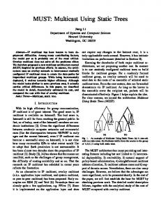
II. P RELIMINARIES A. Behavior Trees The syntax of the BT notation comprises nodes and edges. A node can be either a state realisation describing a state change of a component or one of its attributes, or a selection, guard, or event, guarding the control flow within the BT. A node is specialized by its Component name C, Behavior B, Type, and set of Flags. The Behavior is an identifier (describing a state, an event, or a channel name), or an expression (referring to component attributes). tag
Flag
tag
Component ? Behavior ?
tag
a) State Realisation
tag
Component > Behavior
> Behavior
g) External Output Event
Different node types of the BT syntax
Figure 1 lists the different types of BT nodes: (a) a state realisation, modelling C being in a state if B is a state name, or updating C’s attribute if B is an update expression over the attribute; (b) a selection (or condition) on C’s state if B is a state name, or a selection on the state of one of C’s attributes if B is an expression over the attribute; in both cases, the control flow terminates if the condition is not satisfied; (c) a guard; the control flow can pass the guard when C is in state B if B is a state name, or when the expression B over one of C’s attributes is satisfied if B is an expression over the attribute; otherwise it is blocked until the state realisation occurs; (d-e) an internal event modelling communication and data flow between components within the system, where B specifies an event; the control flow can pass the internal input/output event node when the event occurs (the message is sent), otherwise it is blocked until it occurs; (f-g) an external event modelling communication and data flow between the system and its environment, where B specifies an event; the control flow can pass the external input/output event node when the event occurs (the message is sent), otherwise it is blocked until it occurs. Control flow within the system is represented by either a normal or a branching edge. A normal arrowed edge models sequential flow between two steps. If two nodes are 182
connected by a line without an arrow head, the two steps occur together atomically. Figure 2 shows the two types of branching edges: concurrent and alternative. Concurrent branching (Figure 2a) models threads running in parallel. As an example the threads in the figure start with a guard node. The branches, however, can start with any node type. We show only two sub-trees in the branching, although in general there may be more.
tag
tag
C1 F [ B1 ]
C2 F ?? B2 ??
tag
tag
C3 F ?? B3 ??
tag
C3 F ? B3 ?
...
Figure 2.
BTs can be interpreted as state transition systems and translated into the syntax of a model checker such as SAL [13] or NuSMV [30]. We have developed an automated translation from BTs to the SAL language which provides an interface to the SAL tool suite. This allows for a fully automated analysis of BT models. When translating, BT nodes (or a combination of those) are transformed into actions in the SAL notation which consist of a guard and an update section. Events like internal or external inputs or outputs are translated into Boolean SAL state variables. External input events in particular become SAL input variables which are not controlled by the model and behave arbitrarily. Boolean variables that represent internal events are set to true when the input is sent (by an internal output node) and are set to false either if the input is consumed (by the matching internal input node) or if another step has been taken and the event has not been consumed. This reflects that events are fluent and might be missed. We specify the properties to be checked in linear temporal logic (LTL) [31] and making use of the SAL symbolic model checker. LTL provides a set of temporal operators such as G (always, in every state of the path), F (eventually, in some state in the future) and X (in the next state). Formulas built from these are interpreted over paths and thus referred to as path formulas. To render the transition relation of the SAL model total (a prerequisite for model checking) we add an ELSE action which is enabled if no other action is. That is, all paths in the model are infinite. The notion of paths corresponds to possible scenarios of behaviour that the modelled system can exhibit. More detail about the translation is given in [14], [12]. The following patterns are useful for the formalisation of properties that we employed for validation, verification and cutset computation in our approach. Assume A is a system property (i.e., assertion about the states of the system and its components), B is a path formula, C and D are system components and C_failed and D_failed specifies their failure. • F(A)=>B says that, in any scenario in which A eventually becomes true, B holds. • G(A => B) says that in every scenario, if a state is reached in which A is true, then B holds in the rest of the scenario from that point on. • NOT(F(C_failed AND D_failed)) holds for exactly those scenarios in which at least one of C or D does not fail. This last property will be used when eliminating cutset {C,D} (for example) in Section VI below. BTs have no in-built fairness constraint to ensure that enabled nodes execute in a “timely” fashion (or even even-
F C1 [ B1 ]
C2 F ? B2 ?
...
...
...
a) concurrent flow
tag
B. Model Checking Behavior Trees
b) alternative flow
Branching structures in the BT syntax
In alternative branching (Figure 2b), the control flow follows only one of the branches. Alternative branches can comprise either selections only (for example, as shown in Figure 2b) or only other node types but no selections. Alternative branching over selections operates as a nondeterministic choice over the branches with a satisfied selection condition Bi . If none of the selections is satisfied the behaviour terminates. Alternative branching over nonselections behaves like a non-deterministic choice that is unguarded. Flags in a BT node can specify: (a) a reversion node, marked by ‘ ˆ’, if the node is a leaf node, indicating that the control flow loops back to the closest matching ancestor node (a matching node is a node with the same component name, type and behaviour) and all behaviour started after the matching ancestor node is terminated; (b) a referring node, marked by ‘=>’, indicating that the flow continues from the matching node; (c) a thread kill node, marked by ‘−−’, which kills the thread that starts with the matching node, or (d) a synchronisation node, marked by ‘=’, where the control flow waits until all other threads with a matching synchronisation node have reached the synchronisation point. The BT syntax also includes notation for standard set operations. For instance, assume S is a set then the Behavior S := S + {x} models adding element x to S. Similarly the Behavior S := S − {x} models removing element x from S (for a complete description of the syntax, including set union, set difference and cardinality, see [29]). Type declarations and other structural information about the system model are captured in a Composition Tree (CT). We do not introduce the notion of CTs here but refer the interested reader to [29]. The semantics of the BT notation is formalised in [11]. 183
tually) when there are nodes in other threads which are enabled concurrently. This can become an issue when model checking as it often leads to violations of the checked property due to behaviours which are unrealistic or unfair (such as infinite loops in part of the model, with no progress in other parts of the model). For some models we would like to exclude such unfair behaviour. In general this can be done within the model checker (either using the LTL to impose fairness or the fairness assumption of the model checker’s modelling notation [32]). Since a typical scenario of unfair behaviour is that external input dominates other internal behaviour (a BT model can be busy just reading external input events without ever having the chance of (internally) reacting to this) we provide a solution to this problem within our automated translation to SAL. Our translator provides an option for prioritising internal behaviour over behaviour that is triggered by external input. This assumption imposes a form of fairness onto the model in that it excludes the case whereby a process is busy reading constantly changing external input without getting a chance to react.
B. Safety requirements As described in [8], the three over-riding qualitative safety requirements for systems on which aircraft depend, such as hydraulics, are: 1) at least 3 independent component failures need to occur in order for all h-systems to be lost (a catastrophic system failure) 2) at least 2 independent component failures need to occur in order for two h-systems to be lost (a major system failure) 3) at least 1 component failure needs to occur in order for a h-system to be lost (a minor system failure) (The motor industry has similar qualitative safety requirements for software-based systems in cars.) However, it is not enough to simply prove this is the case. The system designers and safety regulators will also want to know what are the minimal cutsets and co-effectors for the above system failures. That is, precisely which combinations of component failures can lead to system failures, and under what circumstances (such as in what flight modes, or under which operating conditions)? Such information is important for determining whether component failures are truly independent, or whether they could share a common cause. For the sake of simplicity, the scope of the current investigation is restricted to the departure phase of flight, including on-ground taxiing, takeoff and climb to cruise, but not including later stages of normal flight such as decelerating and landing. We assume that the pilot has turned on both engines and EMPy, and exclude pilot error from the current analysis. Nor do we consider and what effect engine activation/deactivation might have on flight (we do however consider its effect on hydraulic power). Finally, we assume that once a component fails it stays failed. These restrictions are made in order to illustrate the approach while avoiding getting bogged down in detail. The model can however easily be extended to cover them, although relaxing some of these assumptions can have significant implications for computational complexity (see Section VII for discussion).
III. T HE A320 H YDRAULICS S YSTEM – A C ASE S TUDY A. Subsystems and components We present the A320 hydraulics system as a case study. This is the hydraulics system of the Airbus A320 aircraft family, which supplies hydraulic power to the aircraft. The case study was originally presented in [8]. An overview of the system can be seen in Figure 3. There are three kinds of pumps in the system: Electric Motor Pumps which are powered by the electric system, Engine Driven Pumps powered by the two engines of the aircraft and a RAT pump powered by the Ram Air Turbine. The system contains a physical sub-system that is composed of three hydraulic channels (called h-systems below) known as Blue, Yellow and Green. The Blue channel is composed of an Electric Motor Pump EMPb, a RAT pump and a distribution line distb. The EMPb is automatically activated whenever there is at least one engine active. The RAT pump is automatically activated if both engines are lost while the aircraft is flying at a speed of greater than 100 knots. The Green channel is composed of an Engine Driven Pump EDPg and a distribution line distg. The EDPg is driven by Engine 1. The Yellow channel is composed of an Engine Driven Pump EDPy, an Electric Motor Pump EMPy and a distribution line disty. EDPy is driven by Engine 2. The pilot activates EMPy while the aircraft is on the ground. The two engines are also controlled by the pilot. A Power Transfer Unit, PTU, opens a transmission from the Green system’s hydraulic power to the Yellow distribution line and vice versa, as soon as the differential pressure between both systems is higher than a given threshold.
IV. T HE B EHAVIOR T REE M ODEL A. The BT model The BT model of the A320 hydraulic system contains 12 components interacting concurrently: the two Engines (Engine1, Engine2), the two Engine Driven pumps (EDPy, EDPg), the two Electric Motor Pumps (EMPy, EMPb), the Ram Air Turbine Pump (RAT), the 3 hydraulic subsystems (Yellow, Blue, Green), and the Power Transfer Unit (PTU). Additionally, we introduce a component PTUy as a modelling artifact representing the OR of the pumps EDPy and EMPy in Figure 3. Each of these components is modelled as a separate thread in the BT. The Aircraft is also included, in order to model different 184
Figure 3.
Overview of the A320 Hydraulic System
flight modes. A System component is included in order to capture relevant system history information, such as which failures have occurred. Figure 4 shows the overall structure of the BT Model.
(e.g., distyFailed=true means disty has failed), which h-systems are available (via a set hset which can have elements bh, yh and gh, standing for the three hsystems), and how many different components have failed so far (numFails).
Initialisation Engine1 EMPy Engine2
PTU
EMPb Figure 4.
PTUy
EDPy
RAT
EDPg
Green
Blue
Yellow [off]
Aircraft
Yellow System >>distyFailed
empyFailedRATFailed
distbFailed
F(INIT)) (Recall that the BT model being checked assumes that standard operating procedures are followed. In Section VII below we relax this assumption.) Moreover, under the above conditions, once the h-systems are activated, they stay active thereafter: SOP2: G(numFails=0 =>G(H_ALL =>X(H_ALL))) The validation process revealed several issues in the model which all have been addressed by modifications. The version described in Section IV-A above is the final, debugged model.
SSR2Va: NOT(F(distyFailed AND distbFailed AND EDPyFailed)) => SSR2V
V. V ERIFICATION OF S AFETY R EQUIREMENTS The main safety requirement from Section III is that at least three independent failures are necessary before all hydraulics power is lost:
This in turn yields a counterexample with cutset {distb, distg}, which we eliminate by adding NOT(F(distbFailed AND distgFailed)) to the antecedent of SSR2Va. This in turn yields cutset {disty, distg}, which in turn yields cutset {disty, distb} (note that this is a subset of one of the earlier cutsets). Next comes {EMPb,disty}, then {distg, EMPb}, then {disty, EDPg, PTU}, then {PTU, EDPg}, then {E1, disty, PTU}, then {PTU, E1, distb}. At this point we decided to see if there were any more 2-point cutsets remaining, so we added G(numFails G(TOTAL_LOSS => numFails>2)) This is essentially the main theorem of Bieber [8]. Note that we are only interested in states of the system after the hsystems have been initialized, hence the use of INIT as an assumption on the left hand side of the implication. (The use of INIT as a proxy for the end of system initialisation is justified by properties SOP1 and SOP2 above.) The second safety requirement is that at least two independent failures are necessary before only one h-system remains active: SSR2: G(INIT => G(card(hset)=1 => numFails>1)) The third safety requirement is essentially a restatement of the SOP1 validation property above, which says that once an h-system becomes active, it will not deactivate unless a component fails. (Recall that we have excluded the case 187
certain threads and/or removing certain subtrees altogether. Unfortunately current BT tools do not support comparison of different models to see where they differ, which would help make this approach more convenient for model readers and writers, but there are plans to do so in future.
Pilot >> startE1 Pilot >> stopE1
> startE1