Scalability and Robustness of Virtual Multicast for Synchronous Multimedia Distribution Petr Holub1,2 , Eva Hladk´ a1 , and Ludˇek Matyska1,2 1
Faculty of Informatics Institute of Computer Science, Masaryk University, Botanick´ a 68a, 602 00 Brno, Czech Republic
[email protected],
[email protected],
[email protected] 2
Abstract. A simple UDP packet reflector for virtual multicast multimedia transfer is extended to form a distributed system of active elements that solves the scalability problem of otherwise centralistic approach. The robustness of such virtual multicast delivery system is also discussed and shown to be better than the native multicast can offer. The maximum latency, important for multimedia transfer and related to the number of hops through the network of active elements, can be kept bounded. Possible support for synchronized multi-stream transfer is also discussed.
1
Introduction
A virtual multicasting environment, based on an active network element called “reflector” [1] has been successfully used for user-empowered synchronous multimedia distribution across wide area networks. While quite robust replacement for native, but not reliable multicast used for videoconferencing and virtual collaborative environment for small groups, its wider deployment is limited by scalability issues. This is especially important when high-bandwidth multimedia formats like Digital Video are used, when processing and/or network capacity of the reflector can easily be saturated. A simple network of reflectors [2] is a robust solution minimizing additional latency (number of hops within the network), but it still has rather limited scalability. In this paper, we study scalable and robust synchronous multimedia distribution approaches with more efficient application-level distribution schemes. The latency induced by the network is one of the most important parameters, as the primary use is for the real-time collaborative environments. We use the overlay network approach, where active elements operate on an application level orthogonal to the basic network infrastructure. This approach supports stability through components isolation, reducing complex and often unpredictable interactions of components across network layers.
2
Synchronous Multimedia Distribution Networks
Real-time virtual collaboration needs a synchronous multimedia distribution network that operates at high capacity and low latency. Such a network can be
composed of interconnected service elements—so called active elements (AEs). They are a generalization of the user-empowered programmable reflector [1]. The reflector is a programmable network element that replicates and optionally processes incoming data usually in the form of UDP datagrams, using unicast communication only. If the data is sent to all the listening clients, the number of data copies is equal to the number of the clients, and the limiting outbound traffic grows with n(n − 1), where n is the number of sending clients. The reflector has been designed and implemented as a user-controlled modular programmable router, which can optionally be linked with special processing modules in run-time. It runs entirely in user-space and thus it works without need for administrative privileges on the host computer. The AEs add networking capability, i. e. inter-element communication, and also capability to distribute its modules over a tightly coupled cluster. Only the networking capability is important for scalable environments discussed in this paper. Local service disruption—element outages or link breaks—are common events in large distributed systems like wide area networks and the maximum robustness needs to be naturally incorporated into the design of the synchronous distribution networks. While the maximum robustness is needed for network organization based on out-of-band control messages, in our case based on user empowered peer to peer networks (P2P) approach described in Sections 3.1 and 5, the actual content distribution needs carefully balanced solution between robustness and performance as discussed in Section 4. The content distribution models are based on the idea that even sophisticated, redundant, and computationally demanding approaches can be employed for smaller groups (of users, links, network elements, . . . ), as opposed to simpler algorithms necessary for large distributed systems (such as the global Internet). A specialized routing algorithm based on similar ideas has been shown, e. g. as part of the RON approach [3].
3
Active Element with Network Management Capabilities
As already mentioned in Sec. 2, the AE is the extended reflector with the capability to create network of active elements to deploy scalable distribution scenarios. The network management is implemented via two modules dynamically linked to the AE in the run-time: Network Management (NM) and Network Information Service (NIS). The NM takes care of building and managing the network of AEs, joining new content groups and leaving old ones, and reorganizing the network in case of link failure. The NIS serves multiple purposes. It gathers and publishes information about the specific AE (e. g. available network and processing capacity), about the network of AEs, about properties important for synchronous multimedia distribution (e. g. pairwise one-way delay, RTT, estimated link capacity). Further, it takes care of information on content and available formats distributed by the
network. It can also provide information about special capabilities of the specific AE, such as multimedia transcoding capability. The NM and NIS modules can communicate with the AE administrator using administrative modules of the AE kernel. This provides authentication, authorization, and accounting features built into the AE anyway and it can also use Reflector Administration Protocol (RAP) [4] enriched by commands specific for NM and NIS. The NM communicates with the Session Management module in the AE kernel to modify packet distribution lists according to participation of the AE in selected content/format groups. 3.1
Organization of AE Networks
For the out-of-band control messages, the AE network uses self-organizing principles already successfully implemented in common peer to peer network frameworks [5],[6], namely for AE discovery, available services and content discovery, topology maintenance, and also for control channel management. The P2P approach satisfies requirements on both robustness and user-empowered approach and its lower efficiency has no significant impact as it routes administrative data only. The AE discovery procedure provides capability to find other AEs to create or join the network. The static discovery relies on a set of predefined IP addresses of other AEs, while the dynamic discovery uses either broadcasting or multicasting capabilities of underlying networks to discover AE neighborhood. Topology maintenance (especially broadcast of link state information), exchange of information from NIS modules, content distribution group joins and keep-alives, client migration requests, and other similar services also use the P2P message passing operations of AEs. 3.2
Re-balancing and Fail-Over Operations
The topology and use pattern of any network changes rather frequently, and these changes must be reflected in the overlay network, too. We consider two basic scenarios: (1) re-balancing is scheduled due to either use pattern change or introduction of new links and/or nodes, i. e. there is no link or AE failure, and (2) a reaction to a sudden failure. In the first scenario, the infrastructure re-balances to a new topology and then switches to sending data over it. Since it is possible to send data simultaneously over both old and new topology for very short period of time (what might result in short term infrastructure overloading) and either the last reflector on the path or the application itself discards the duplicate data, clients observe seamless migration and are subject to no delay and/or packet loss due to the topology switch. This scenario also applies when a client migrates to other reflector because of insufficient perceived quality of data stream. On the contrary, a sudden failure in the second scenario is likely to result in packet loss (for unreliable transmission like UDP) or delay (for reliable protocols like TCP), unless the network distribution model has some permanent
redundancy built in. While multicast doesn’t have such a permanent redundancy property, the client perceives loss/delay until a new route between the source and the client is found. Also in the overlay network of AE without permanent redundancy, the client needs to discover and connect to new AE. This process can be sped up when client uses cached data about other AEs (from the initial discovery or as a result of regular updated of the topology). For some applications, this approach may not be sufficiently fast and permanent redundancy must be applied: the client is continuously connected to at least two AEs and discards the redundant data. When one AE fails, the client immediately tries to restore the degree of redundancy by connecting to another AE. The same redundancy model is employed for data distribution inside the network of AEs, so that re-balancing has no adverse effect on the connected clients. The probability of failure of a particular link or AE is rather small, despite high frequence of failures in global view of large networks. Thus the two fold redundancy (k = 2) might be sufficient for majority of applications, with possibility to increase (k > 2) for the most demanding applications.
4 4.1
Distribution Models Multicast Schemes
In an ideal case, the multicast organization of the data distribution is the most efficient scheme to distribute data to multiple clients. However, it is very difficult for a user to place AEs into the physical network topology in such a way that no data will pass through any physical link twice. The only exception may be when AE network is implemented as a network of active routers, but this goes against the user-empowered approach we support. Thus the multicast paradigm is only an upper-limit on efficiency of the distribution. There are two basic approaches to build multicast distribution tree: sourcebased tree also known as shortest path tree (SPT) and shared tree. Regarding the synchronous character of multimedia data distribution, the SPT with reverse path forwarding (RPT) has two major advantages: it minimizes latency compared to shared tree where the data is sent through rendezvous point and it provides shortest paths between the source and the receivers (advantage for large volume of data transmission). To build SPTs, it is necessary to have underlying unicast routing information. This information can be maintained very efficiently by RON [3]. As an addition to fast convergence in case of network link failure, it is possible to define policy to select the shortest path not based on hop count, but based on path round trip time or even one way propagation delay if available. Fail-Over Operation Standard operation when the link failure occurs is to build a new SPT as described above. If even the convergence speed of RON is not acceptable, there is another possible strategy to minimize delay due to SPT reconstruction. It is possible to compute multiple SPTs at the same time,
received packets per second
30 25 20 15 10 5 0 170
180
190
200 time [s]
210
220
230
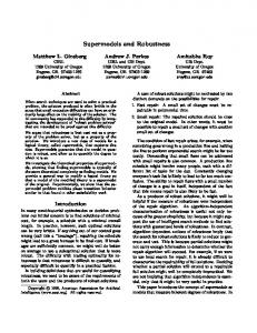
Fig. 1. Recovery time for with backup SPT (solid line) and without it (dashed line) simulated using cnet-based network simulator.
choose single SPT for data distribution and keep the remaining SPTs for failover operation. For permanent redundancy scenario, more than one SPT can be used simultaneously and duplicate data will be discarded by client applications. In full graph, there are n2 −n links between the AEs. For a small number of AEs, alternative SPTs can be computed that don’t use one selected link at a time. If that particular link fails, the alternative SPT can be immediately switched on. For larger number of AEs where number of links is too large, it is possible to compute bn/2c possible SPTs with disjunct set of links. When using SPTs or shared trees (ST) with backup based on disjunct sets of links, it is necessary to ensure that not all links from one AE are used in one SPT/ST, since the AE would become isolated in backup SPT/ST. When backup SPT/ST is available, the network recovery is limited just by broadcast speed to announce switching to a new SPT/ST, but when there is no backup, the alternative SPT/ST must be computed first (Fig. 1). During the normal operation, all these SPTs are monitored for their usability and when link fails in the current SPT, the original SPT can be swapped for another working SPT if at least one other usable SPT is available. 4.2
2D Full Mesh
The simplest model with higher redundance, serving also as the worst case estimate in terms of scalability, is a complete graph in which each AE communicates directly with all the remaining AEs. This 2D full-mesh tunneling model was studied and described in detail in [2] Let’s assume a 2D full mesh of reflectors, each populated with nr clients. The limiting traffic in this mesh is again the outbound traffic on the AE which scales as out = n2r m + nr (m − 2). Fail-Over Operation When a link or whole AE drops out in the full mesh, the accident only influences data distribution from/to the clients connected to that AE. In case of link failure inside the AE mesh, the client is requested to
migrate to an alternative AE. In case that AE itself fails the client initiates migration on its own. Alternative AEs should be selected randomly to distribute nr e. When even this load increase more evenly and the load increase will be d m−1 migration delay is not acceptable, it is possible for a client to be permanently connected to an alternative AE and just switch the communication. For even more demanding applications, the client can use more than one AE for sending in parallel. Although this model seems to be fairly trivial and not that interesting, it has two basic advantages: first, the model is robust and failure of one node influences only data from/to the clients connected to that AE. Second, it introduces only minimal latency because the data flows over two AEs at most. Next we will examine another model that has the same latency and robustness properties but that scales better. 4.3
3D Layered-Mesh Network
The layered mesh model creates k layers, in which data from a single AE are only distributed. That means each client is connected to one layer for both sending and receiving (sending only if nr = 1; in other cases the client needs to receive data from remaining nr − 1 clients of the AE used for sending) and to all other layers for receiving only. Each layer comprises 2D full mesh of m AEs. For the sake of simplicity, we first assume that k = m and each AE has nr clients, thus n nr = m = nk . In this scenario, the number of inbound streams is in = nr . Number of outbound streams is out s/r = n2r + nr (m − 2) if the sending client is connected to this particular AE, and out r = n2r when only receiving clients are connected. This model is problematic because of increasing the number of AEs used. However it seems to be the last model that doesn’t introduce intermediate hops and thus keeps hop-count at minimum. Intermediate AEs Let’s create q-nary tree used for distributing data from AE with sending clients to m − 1 AEs with listening clients. When building q-nary tree with λ intermediate layers λ = logq (m − 1) − 1, the total number of P intermediate AEs is L = λp=1 q p = m−1−q q−1 . Flows in this type of network are as follows: out s/r = nr (nr − 1) + qnr for outer AE with sending clients connected, out r = n2r for outer AE with only receiving clients, and out i = qnr for inner intermediate AEs. For all types of AEs, the number of inbound flows is nr . There are however two disadvantages of this model: – The number of hops inside the mesh of AEs increases by λ compared to the plain 3D mesh model. – Compared to the plain 3D model, the number of the intermediate AEs further increases to mtot = mk + Lk. For m = k, it becomes mtot = m(m + L). Nevertheless, this model provides the same redundancy while improving scalability compared to the simple 2D mesh.
Fail-Over Operation Each of the mesh layers monitors its connectivity. When some layer disintegrates and becomes discontinuous, the information is broadcasted throughout the layer and to its clients. The clients that used that layer for sending are requested to migrate to randomly chosen layer from the remaining k − 1 layers and the listening-only clients simply disconnect from this layer. Such behavior increases load on the remaining k − 1 layers but as the clients choose nr e. the new layer randomly, the load increases in roughly uniform way by d k−1
5
Content Organization
The multimedia content can be encoded in many different formats, that suit specific needs or capabilities of the network and the listening clients. In some cases (e. g. MPEG-4 formats) the highest quality format can be decomposed into N different layers (groups) that are sent over network independently. When native multicast is used, the client subscribes for the first M ∈ h1; N i groups only, thus controlling the quality reduction of received content. With native multicast, there is no easy way to prioritize and synchronize the streams, which may lead to unexpected loss of quality (if data in the first layer are lost, the other layers may render useless). As AEs support also multimedia transcoding (capable of being active gateways), an extended approach can be used. The format decomposition or even transcoding to completely different format may be performed by an AE, providing a flexible on demand service–the transcoding occurs only if really needed by some client. Also, the AEs are capable of synchronizing individual streams—they “understand” the decomposition and may re-synchronize individual streams. In case of severe overload, the higher (less important) stream layers are dropped first (again, AEs know the hierarchy), so the transmission quality is minimally affected. To formalize our approach, we have designed three layer hierarchy: – content groups—the highest level, an aggregation of several contents; it can be for instance a videoconferencing group (e. g. video and audio streams of individual videoconference participants) – content—intermediate level, a content (a video stream, format independent) – format—the lowest level, format definition. Each multimedia stream in the network is then characterized by (content group, content, format) triplet which creates one record in the SPT tree. The available formats for each content create an oriented graph where the root is the source format and the child nodes define the formats created from their parents. A client can choose the best suitable format, or different formats for different contents within one content group (e. g. a lecturer’s stream with the highest quality). The information about available content groups, content, and available formats is published via NIS on AEs and is distributed and shared across the network of AEs.
6
Related Work
There are a few known applications for synchronous distribution of multimedia data over IP networks. Probably the most important ones are cascading of H.323 multi-point connection units (MCUs) and Virtual Room Videoconferencing System (VRVS). The networks of H.323 MCUs are based on a static preconfigured topology and they don’t offer user-empowered approach. The VRVS is only provided as a service and the users’ traffic is managed by VRVS administrators. Also, although the VRVS team reports some move in favor of more elaborate and dynamic network of reflectors, we believe that creating flexible user-empowered multimedia network is more suited for open systems without centralized administration.
7
Conclusions
In this paper the models for the virtual multicast scalability were introduced with discussion of robustness and fail over capabilities of the proposed solutions. We have implemented a prototype of Active Element suitable for simple networking scenarios for Linux and FreeBSD operating systems and the models have also been verified using network simulator. The AE network organization support is being implemented based on JXTA 2.0 P2P framework. The full application-level multicast data distribution with multicast subgroups as described in Secs. 4.1 and 5 is under development.
8
Acknowledgment
This research is supported by a research intent “Optical Network of National ˇ 6383917201). We would also like to Research and Its New Applications” (MSM thank to Tom´ aˇs Rebok for helping with implementation of network simulations.
References 1. Hladk´ a, E., Holub, P., Denemark, J.: User empowered virtual multicast for multimedia communication. In: Proceedings of ICN 2004. (2004) 2. Hladk´ a, E., Holub, P., Denemark, J.: User empowered programmable network support for collaborative environment. In: ECUMN’04. Volume 3262/2004 of Lecture Notes in Computer Science., Springer-Verlag Heidelberg (2004) 367 – 376 3. Andersen, D., Balakrishnan, H., Kaashoek, F., Morris, R.: Resilient overlay networks. In: 18th ACM Symp. on Operating Systems Princpiles (SOSP), Banff, Canada (2001) 4. Denemark, J., Holub, P., Hladk´ a, E.: RAP – Reflector Administration Protocol. Technical Report 9/2003, CESNET (2003) 5. Rowstron, A., Druschel, P.: Pastry: Scalable, distributed object location and routing for large-scale peer-to-peer systems. In: IFIP/ACM International Conference on Distributed Systems Platforms (Middleware), Heidelberg, Germany (2001) 329–350 6. Yang, B., Garcia-Molina, H.: Designing a super-peer network. In: IEEE International Conference on Data Engineering. (2003) 25