SCALABLE DSP IMPLEMENTATION OF DCT-BASED MOTION ESTIMATION ALGORITHM Miia Viitanen, Pasi Kolinummi, Timo Hämäläinen and Jukka Saarinen Digital and Computer Systems Laboratory, Tampere University of Technology P.O. Box 533, FIN-33101 Tampere, FINLAND e-mail:
[email protected]
ABSTRACT A parallel implementation of a DCT-based motion estimation algorithm (DXT-ME) for 2D images/signals is presented for a parallel scalable DSP system called PARNEU. PARNEU was used to test the performance of the parallelism. The DCT-based motion estimation can be used for video coding instead of the more frequently used full search block-matching approach (BKM-ME). The DCT-based system has lower computational complexity compared to the BKM-ME and it can result in a higher system throughput. Data parallel implementation scales very well and the performance measurements are promising compared to the traditional methods.
1. INTRODUCTION The DCT (discrete cosine transform) pseudophase techniques were developed to improve the motion estimation from twodimensional (2D) signals or a sequence of images. Motion estimation is one of the most important stages in modern video encoders and its performance is therefore crucial to the whole image encoder. In many cases, the motion estimation is the slowest stage in video encoding [1]. For these reasons, a parallel implementation with efficient and promising algorithm was examined. The main issue was whether the implementation will improve and speed up motion estimation stage. The DCT pseudophase techniques employ sinusoidal orthogonal principles to extract shift information from the pseudophases hidden in the discrete cosine transform (DCT) coefficients of images. Under the 2D translational motion model, the techniques result in the DCT-based motion estimation algorithm (DXT-ME), which estimates displacements in the DCT domain [2][3]. The DXT-ME algorithm has certain advantages for example over the most commonly used motion estimation scheme, the full search block-matching approach BKM-ME [3]. The BKMME searches for the best match between the current block and the reference blocks found within a search area. Instead, in the DXT-ME the search area is the same as the candidate block, which is a major difference between the two algorithms [3].
Section Three. Section Four explains how parallelism is accomplished with this algorithm. Algorithm’s performance, complexity and computational requirements are considered in Section Five. In Section Six a short summary is presented.
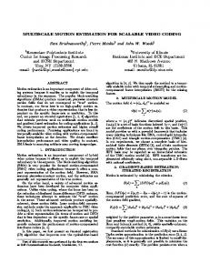
2. DXT-ME ALGORITHM The DXT-ME algorithm consists of four main steps as illustrated in Figure 1 [2]. First, the current frame xt is fed into 2D DCT-II coder and the previous frame xt-1 is transformed with 2D DCT-I. A 2D DCT-II coder computes four coefficients: DCCT-II, DCST-II, DSCT-II and DSST-II. Coefficients are computed so that one-dimensional (1D) discrete cosine/sine transform of type II is performed two times to the input - first to the columns and then to the rows. For example, DCST-II means one-dimensional cosine transform on the columns and onedimensional sine transform on the rows. The problem of adding a separate 2D DCT-I unit to compute the previous frame can be circumvented with an additional coefficient transformation unit (T) that has a simple structure. This T-unit is formed by considering a point-to-point relationship between 2D DCT-I and 2D DCT-II coefficients in the frequency domain [2]. For instance in H.263 encoder [4][6], 2D-DCT of type II is always computed but the DXT-ME needs an additional 2D-DST coder. For data streams, the 2D-DCT transform may be performed only once for each frame if the result of the previous frame is stored in the memory. Transformation from the DCT-II to the DCT-I is needed for each frame. xt
xt-1 2D-DCT-II
1.
T 2.
Compute Pseudo Phases f(k,l)
g(k,l) 2D-IDCT-II
3.
In terms of computational complexity the DXT-ME outperforms the BKM-ME. BKM-ME’s complexity is O(N2⋅ M2) for the search range of M×M and for the block size of N×N. The computational complexity of the DXT-ME is O(N2) and it depends only on the block size. In addition, the DXT-ME algorithm enables combining both the DCT and motion estimation into a single component, thus reducing the video encoder complexity.
Figure 1. Block diagram of DXT-ME structure [2].
In this paper, a parallel mapping of the DXT-ME on PARNEU system is presented in detail. The next section introduces DXTME algorithm. PARNEU’s architecture is described briefly in
At the second stage, as shown in Figure 1, the estimated pseudophases f(k,l) and g(k,l) are computed. They can be derived from a set of equations, which relate DCT coefficients
DCS(m,n) 4.
DSC(m,n)
Determine Displacement Estimated displacement (x,y)
of xt−1(m,n) with those of xt(m,n). In the computation of f(k,l) and g(k,l) if the absolute computed value is greater than one, then the value is discarded and set to zero. This deletion of illconditioned values is found to improve the overall performance of the DXT-ME algorithm. Next, these two pseudophase functions pass through 2D IDCT-II (2D inverse discrete cosine transform) coders generating two functions called DCS(m,n) and DSC(m,n). Inverse transforms are again accomplished so that one-dimensional inverse discrete cosine/sine transforms are performed to the columns and to the rows. The displacement vector is found from these functions by locating the peaks of DCS and DSC [2]. The peak signs determine the direction of the movement.
3. PARNEU ARCHITECTURE PARNEU [5] is a linearly scalable DSP system that is connected to a host computer. It consists of modular processing cards each carrying four DSPs that are connected to a master controller and further to a host computer, as shown in figure 2. The host computer is a PC with WindowsNT operating system. It is used for program initialisation and monitoring. The master PU card controls the operations inside PARNEU system. It has good connections to host computer and an additional dynamic random access memory (DRAM). The PARNEU hardware is implemented with ADSP-21062 digital signal processors working as processing units (PUs) and Xilinx field programmable gate arrays (FPGA) that perform the communication operations. Each PU has its own internal 256 kilobytes SRAM memory. The processing units and communication circuits work on 40 MHz system clock. The communication structure is very flexible. A global bus connects all cards to the master for efficient broadcast operation. Adjacent DSPs are connected by a serial ring bus. Thus, data can be circulated between PUs in a systolic way. The third way to move data is a reconfigurable partial tree structure that is formed from the FPGAs located in each card. The tree network can perform global reduction operations like summation and comparison operations as well as pre- or postprocessing operations if external devices, like cameras, are connected.
information from the previous phase and thus a pipelined implementation could be used. The pipelining does not decrease latency time, but increases the system throughput. Implementation also requires a large memory area to buffer input data and to store intermediate results. Further, including the pipelined DXT-ME algorithm for example to H.263 video encoder [4][6] would be difficult because of the different block size and global feedback loops in video encoder structure. Therefore, in the eyes of performance and easy realization, data parallel implementation is preferred. It does not require active communication between the master and slave PUs, it needs no connection establishment between slave PUs and it deals with small pieces of the image. However, this contradicts with the requirement of the DXT-ME algorithm, which prefers large data block size for better performance in video quality. To save memory, a block size of 16×16 pixels was still chosen. Moreover, the implementation is easier to include in a data parallel video encoder structures to replace the BKM-ME algorithm. However, the block size is not a difficult task to change if needed. Algorithm computation occurs between two consecutive frames. Image data is stored to the host computer’s memory – only the required blocks in computation are sent further. In the beginning, the host computer initializes the PARNEU system and arranges images to suitable size blocks (11×16×16). Block size was chosen this way, because one image is easily divided to these nine same sized blocks and furthermore, every processor can thus always perform the same code. The host computer then sends the first parts of the images to the master PU as shown in Figure 3. The master receives data and further distributes it to the slave PUs via the global bus. The data could also be transmitted directly from camera to the slave PUs via the reconfigurable partial tree network, which can be configured to accept different data formats and divide the data to the PUs in a predefined manner.
Divides an image into 176x16 blocks and sends to PARNEU
A. Sends 11x16x16 blocks to slaves
Divides 176x16 blocks into 16x16 blocks
B. Computes DXT-ME for 16x16 block
BU Local bus
Global bus
BU
Stores results and continues if blocks left
Ring bus
C.
Tree bus
Ext.
Receives results and starts a new cycle
One processing card Ext. Tree unit
Receives results and sends them to PC
Sends results to the master
BU
Processing unit BU Ext.
Bus unit External connector
Host computer
Figure 2. Block diagram of PARNEU.
4. PARALLEL IMPLEMENTATION Parallelization can be done either by dividing each image into small blocks or by dividing the algorithm phases to different processors. The phases of the DXT-ME algorithm need a lot of
Shuts the connection to PARNEU Host
Master
Figure 3. Block diagram of implementation on PARNEU.
Slave PU
DXT-ME
algorithm’s
Only on the first round, it is necessary to send the previous and the current frame (frame 1 and 2). All the other rounds it is sufficient to send only the current frame (on the second round
frame 3) because needed matrices from the previous frame are still in the memory. The memory allocated to previous frame can thus be freed after the first round. The memory reserved to the current image is always reused. Thus, the new image data always overwrites the old one. In the current implementation, the master sends 11 reference blocks of size 16×16 pixels to each slave PU via the global bus. Each PU processes the 11 reference blocks serially. The number of transmitted blocks is selected to be more than one because each communication operation has an initial latency time that would decrease the performance. Larger data blocks would decrease the communication time, but the size of blocks is limited because of the memory capacity. The slave PUs perform the parallel computation of the DXTME algorithm using 16×16 reference blocks. The computation of the motion vectors of a reference block does not need any data from the other blocks and thus the parallel computation can be done without any communication to other slave PUs. Having computed one block, the results are stored in PUs memory and the second block, which is already in PUs internal memory, is taken for computation. When all blocks are computed, each PU sends the local results in one package to the master, which transmits them to PC. This process is repeated until the whole data has been analyzed as it is depicted in Figure 3. Each slave PU computes the same program but with different data. The core of the DXT-ME algorithm, as illustrated in Figure 1, is implemented using the fast DCT-II –transformation algorithm [7] in the first step. Two-dimensional transformation is carried out so that the one-dimensional DCT-II is done first to the columns of the blocks and then to the rows [2]. DST-II – transformation, which is also needed in the first step, is done via DCT-II transformation [8]. The matrices counted for the current frame xt in this step are saved in memory for the next round. This way they need not to be counted again but the type conversion of DCT-II to DCT-I, which is done through the coefficient transformation unit (T), can be done directly to these intermediate results. Pseudophases are computed and inverse transforms are again done with the same fast computational algorithm like DCT-II – just doing it from the end to the start. Displacements are finally found from two functions by locating their peaks, which come out from the inverse transforms.
5. PERFORMANCE A workload in each PU is identical when the number of data blocks can be divided equally by the number of processing units. In any case, the load balance is very good. The application scalability limit is reached when each PU has only one 16×16 data block. Even for small QCIF picture (176×144) the theoretical limit will be 99 processors. In reality, this would no longer be reasonable, because the real-time performance is reached with smaller configuration and the efficiency will decrease because of increased communication demands. At present, PARNEU system has one card with four processors. The scalability requirement has been met in both application software and PARNEU hardware implementation and thus new processing cards can be easily added to the system. The presented DXT-ME realization works directly with eight PUs. When the number of processors is higher than eight the sizes of 11×16×16 data blocks that are sent to PUs have to be decreased. On the other hand, the picture size could be higher in a larger system. This will redress the balance between communication and computation. The number of clock cycles of the core DXT-ME algorithm for a single 16x16 block is shown in Table 1. The step notation is the same as in Figure 1. In PARNEU 16x16 data blocks are
computed in parallel in each DSP (phase B in Figure 3). However, Table 1 shows the sequential times for Analog Devices ADSP-21062 and Compaq Alpha processor. Both programs are written in C-language, and therefore the step times can be compared. However, the DSP-program can be further optimized by using assembly language. ADSP processor seems to be more effective in each operation but especially the computation of step 2 is much faster. With same clock frequency, the Alpha with Unix gcc-compiler is not as fast as SHARC. Table 1. Number of clock cycles of the DXT-ME algorithm phases for a 16×16 (N×N) block in ADSP20162 and Compaq Alpha processor (500Mhz). Step
Clock Cycles in SHARC
1. T-unit 2. 3. 4.
172300 140100 83700 75100 11000
Clock cycles in Compaq Alpha 190300 146300 120200 99300 11000
Complexity
O(N) O(N2) O(N2) O(N) O(N2)
Computational complexities i.e. the absolute upper limits are also presented in Table 1. It can be summarized that the overall complexity of DXT-ME is only O(N2) [3]. Based on the actual implementation in C-language, the number of instructions required for the algorithm execution for a 16×16 is about 838500, of which 442000 are arithmetic and logical instructions. The count of the operations required in the pseudophase computation (a part of step 2) has been computed for a 16×16 block. Total number of needed operations is 18944 [3]. Clock cycles consumed solely by the pseudophase computation is 28800 for the Alpha processor and 26500 for the ADSP processor. Thus, the greater part of the operations required and clock cycles used is not needed in the essence of this algorithm. In most implementations of video encoders the DCT-II transformation is located inside the loop of temporal prediction. Separate units for an IDCT-II transformation and a spatialdomain motion estimator (SD-ME), which is some motion estimation algorithm (for example BKM-ME), are also used [3]. In DXT-ME these transformations are done inside the algorithm, which leads to simpler encoder structure. Though for fair comparison to other motion estimation schemes, the DCT and the IDCT transforms (steps 1 and 3), which take much of the time, can be partially neglected. Although finding more efficient algorithms for 2D-DCT may decrease these times. Coefficient transformation (T-unit) seems to take most of the time although it is considered as a simplifying unit to speed up computation. Actually, a separate DCT-I unit is more profitable if the intermediate results from the previous round are not in use for example because of the limited memory capacity. If DCT transforms (DCT-II and DCT-I) are done separately and effectively in a pipelined manner elsewhere in the video encoder, they can be ignored in performance analysis of the DXT-ME algorithm. IDCT (step 3) on the other hand is needed in the algorithm between two important stages and therefore it is hard not to consider it. Another problem with the DCT/IDCT steps is that a discrete sine transform unit is also necessary. Because normally this unit is not needed, it makes the performance analysis even more difficult. This feature was here chosen not to be significant. Thus, the rest of the algorithm
(steps 2, 3, 4) is essentially needed to find motion vectors and its performance is therefore used to find the performance limits. If the DCT transforms are computed effectively elsewhere in the encoder, the performance for DCT-based motion estimation algorithm in one ADSP-21062 processor (40 MHz) is about 2,4 QCIF frames per second. Thus, by ignoring communication delays PARNEU system with one processing card could reach about 9 frames per second. Using one of the fastest generalpurpose processor, namely 500MHz Alpha, about 21,9 frames per second can be computed without DCT operations. However, the computational burden of the algorithm is quite high and some modifications to reduce the computation are needed. Table 2 shows the measured number of clock cycles for communication and execution inside the PARNEU system for one 11×16×16 macroblock. The used clock frequency is 40 MHz. The communication time is less than 0.5 percentage of the total time used, which verifies the used mapping strategy. The speedup values are almost ideal for reasonable size PARNEU configurations. The equations illustrate the changes in the communication times when either the number of PUs (P) or the data block size (I) are changed. They can be generalized and used to predict changes in communication times. In QCIF pictures as illustrated in Figure 3, at the phase A 176×16 words (a part of the image) is sent in the first round two times (the current and the previous frame) to each slave PU. All the other rounds only the current frame is sent because the matrices for the T-unit transformation of the previous frame are still in the memory. Time is shown for only one 176×16 data block in Table 2. In phase C, result vectors are sent from each slave PU to the master. The results, which are counted at phase B, are the displacement vectors (I=2×11) for those 11×(16×16)=176×16 macroblocks. Table 2. Number of clock cycles of the parallel implementation of the DXT-ME on 176×16 data block. Phase
Step Equations
A
P × (184+3×(P/4)+I×3)
Measured Clock Cycles In SHARC 34540
B
11×DXT-ME
5304200
C
P×(172+3×(P/4)+I×3)
964
PARNEU’s communication structure is good enough for parallel implementation, but slave processors internal memory restricts the possible block sizes as well as the capability to store intermediate results of the previous frames. Especially, the result of the previous frame 2D DCT-II coefficients should be stored to prevent the computation of the same values again. In PARNEU the biggest problem with this structure is the limited memory capacity of PUs. The storage of intermediate results would require 3×11×4×16×16=33792 words of empty memory space in each PU when the computation is done using 32 bits floating-point numbers. However, currently each PU has only 64 kilowords of internal SRAM memory. About half of the memory is used for program codes and stack. The rest is reserved for image data and intermediate results from which the basic computation data needs about 7 kilowords. In PARNEU the intermediate results have to be stored in the DRAM memory of the master card and thus the PUs need to send the intermediate results to the master after computation of one 16×16 block. The master should return the data when computing the next image. However, it was observed that saved
time in computation of the T-unit was squandered elsewhere on communication between the master and PUs. Time in step 1 in Table 1 increased to 338000 clock cycles, while others were not affected. Thus for PARNEU architecture the implementation is not the most effective, although it can save time in different kinds of architectures where memory size is not a restrictive factor. The performance of DXT-ME algorithm can be compared to the performance of BKM-ME. The BKM-ME scheme with the sum of the mean square error criterion has been implemented on PARNEU using search range of 8 pixels and 16×16 reference blocks. The C-language realization takes about 315200 clock cycles, while 16 pixels search range requires about 791400 clock cycles. It should be noted that optimized assembly level realization in BKM-ME is many times faster. Reached displacement vectors with DXT-ME are not as accurate as with BKM-ME. Algorithm properties have been analyzed in [2][3]. There was remarked that results could be improved with a simple pre-processing to the video stream [3].
6. CONCLUSIONS In this research, the possibilities for parallel and scalable implementations and computational requirements for DCTbased motion estimation were the major interests. In general, the DXT-ME seems to be suitable for parallel implementation, because the core of the algorithm can be computed locally in PUs. Problems in implementing this algorithm to PARNEU were mainly encountered due to the limited memory capacity of PUs, which restricts the possible block sizes as well as the capability to store intermediate results of the previous frame. Currently the realization of the DXT-ME performs only a few frames per second, but assembly level optimization and the development of computationally easier algorithms for the internal steps of DXT-ME would lead to radical performance increase. Thus, the DXT-ME can be a true rival on the area of image processing.
7. REFERENCES [1] A. Launiainen, A. Jore, E. Ryytty, T. Hämäläinen and J. Saarinen, “Evaluation of TMS320C62 Performance in Low Bit-rate Video Encoding”, IEEE Multimedia Technology and Applications Conference (MTAC98), Anaheim, USA, September 1998, pp. 364-368. [2] U.-V. Koc, “Low Complexity and High Throughput Fully DCT-Based Motion Compensated Video Coders”, Ph.D. Thesis, The University of Maryland, USA, September 1996. [3] U.-V. Koc and K.J. Ray Liu, “DCT-Based Motion Estimation”, IEEE Transactions on Image Processing, Vol. 7, No. 7, July 1998, pp. 948-965. [4] ITU-T Recommendation H.263, “Video coding for low bit rate communication”, March 1996. [5] P. Kolinummi, P. Hämäläinen, T. Hämäläinen and J. Saarinen, "PARNEU: General-Purpose Partial Tree Computer", Microprocessors and Microsystems, Vol. 24, No. 1, March 2000, pp. 23-42. [6] V. Bhaskaran and K. Konstantinides, Image and Video Compression Standards – Algorithms and Architectures, Kluwer Academic Publishers, USA, 1995. [7] W.-H. Chen, C. Smith and S. Fralick, “A Fast Algorithm for the Discrete Cosine Transform”, IEEE Transactions on Communications, Vol. Com-25, No.9, September 1977, pp. 1004-1009. [8] K. Rao and P. Yip, “Discrete Cosine Transform”, Academic Press Inc, USA, 1990.