Scalable Models for Autonomous Self-Assembled Reconfigurable Systems T. Cervero, S. Lopez and R. Sarmiento Inst. of Applied Microelectronics (IUMA) University of Las Palmas de Gran Canaria E-35017, Las Palmas de Gran Canaria, Spain Email: tcervero,seblopez,
[email protected]
Abstract—FPGAs are well-suited for applications that need to adjust the composition of computational structures over the lifetime of the application. While the underlying hardware framework for supporting run-time reconfiguration has existed for years, there have been negligibly few FPGA applications that have benefited from this. This is likely not an issue with FPGA architectures, yet is more likely a formulation problem due to a highly restrictive model for reconfiguration provided by the vendors. This paper proposes two alternative models for the assembly of computational structures that is conducive to autonomous self-assembled embedded systems. Furthermore, this paper introduces a paradigm where multiple designs may compete for resources in the same die. To illustrate this, an example is examined that is based on two competing video image processing tasks. Keywords-Field-programmable Gate Array; Dynamic reconfiguration; Modular-Assembly; Tile-Model Assembly
I. I NTRODUCTION For nearly two decades, the FPGA community has recognized the potential value of having a computational platform change its functionality over the course of an application. Several conceptual models have been created to facilitate development, including virtual hardware, hardware contexts, adaptive hardware, and adaptive fault recovery – all clearly conveying the potential of this capability. In the 1990s, the granularity of reconfiguration was on whole-chip reconfiguration. Many academic projects at this time focused on software tools and operating systems to manage run-time overlays or contexts. While these endeavors have been innovative, none transferred out of academia into practice due to the tool process complexity, relatively low density devices, yielding limited actual benefits. The justification for reconfiguration has risen as the densities of contemporary devices increased – at least in the academic community. With more computational units crammed within a single device, the greater the propensity to tweak individual units at run time also increases. Many theoretical papers and conceptual prototypes have been produced in recent years on this topic, and one vendor had provided architectural support for finer-grain reconfiguration [1]. Despite this, a chasm remains between theory and practice, and the process of run-time reconfiguration remains awkward in both application development and run-time deployment. The hypothesis
T. Frangieh and P. Athanas Virginia Tech Configurable Computing Lab Dept. of Electrical and Computer Engineering Blacksburg, Virginia (USA) Email: tannous,
[email protected]
examined in this paper is that this gap is attributed to an overly constrained model of reconfiguration. A set of image processing operations are used as a means of illustrating possible enhancements to current models. In real applications, an FPGA may be delegated several computational tasks, and these tasks may be in competition for the allocation of on-chip resources. Furthermore, the computational demands of the tasks may be subject to change over the lifetime of the application. As in software on a multicore processor, it can be advantageous to dynamically allocate resources, and to change interconnectivity as the application progresses. This is clearly apparent in, say, an embedded video application where factors such as radio link quality, video source quality, ambient conditions all may be factors that influence the optimal mix of run-time resources. Current FPGA flows however, fail to address the computational requirements of many applications, hampering the widespread and usability of such platform in various application domains. In this work, we propose a new paradigm of viewing FPGA designs in general, and the partial reconfiguration flow in particular. The work looks at partial reconfiguration from a different perspective that bridges the gap between finer grain reconfigurability, design flexibility and resource utilization. The rest of the paper is organized as follows. Section II introduces a flexible model for overcoming the limitations of commercial tools in reconfigurable devices. Sections III and IV propose two new assembly method as an alternative to current reconfiguration practices. Section V illustrates a case study based on two applications with different characteristics, interacting and competing over logic resources. Finally, in Section VI we conclude and give directions into future work. II. U NRESTRICTED M ODULE FOR R ECONFIGURATION The issue examined in this paper can be stated more broadly as a capability that would allow the arbitrary assembly of computational functions at run time. The assumption here is that the number of possible combination of configurations needed by the system is unmanageably large, and the possibility of precomputing all of them in advance is not viable, or the ensemble of configurations exceeds the storage requirements of the system. As of now, of the two leading FPGA vendors, Xilinx is the only one that has an open bitstream data structure
that makes this run-time assembly of computational functions viable [2]. In many applications, the autonomous assembly of full bitstreams is perfectly acceptable, and is not excluded in this discussion. When it is essential that portions of the FPGA remain online at all times, or if there is state that must be preserved during reconfiguration, then partial reconfiguration is the only viable option. In this paper, the term partial reconfiguration refers to the process of modifying a portion of an FPGA configuration bitstream, yet does not restrict the application to online partial run-time reconfiguration. The Xilinx Early Access Partial Reconfiguration (referred to as the Xilinx PR model) was first offered in 2006 [1]. The slot-based PR model in which it was based remains the only supported model today. The properties of this model are common knowledge, and won’t be discussed here. The underlying assumption of this model is that there is a fixed rectangular hole in an invariant design with fixed terminals around the perimeter. If all of the variant computations require the same input/output terminals, and are all roughly the same size, then this model of computation could be beneficial; however, the vast majority of signal processing computations do not have such a regular structure, and do not easily fit nor can be adapted to this model. The image processing examples presented in this paper are representative of this. While this model has been popular in academia, there is little evidence that there are more than a handful of deployed applications that have demonstrated benefit from this model of computation. Since the Xilinx PR model imposes restrictions on geometry and connectivity, alternative models are explored here that relax these constraints. Two models are presented, and both share the characteristics that there is no pre-defined slot or hole in the invariant design, and that modules can be relocated (to the extent of allowed by the tiles that comprise the module). The first model examined here relies on a library of pre-compiled modules with terminals strategically placed. A computation is built by selecting the modules from the library, relocating them within the FPGA so that they abut, and adjacent terminals on the modules’ perimeter mate. This mode of assembly was demonstrated by Schuck [3] and by Carver [4], and is adapted here in a SVC decoder. This abutment mechanism eliminates the need for routing nets between modules. This model works well for tiled computations, but for a more general class of computations with irregular topologies, more sophisticated module connectivity is needed. To address this, a second model is presented where, at run time, modules are relocated to a desirable position on the FPGA, but do not necessarily abut. Instead, a run-time router forms the necessary connections using the programmable interconnect. This model was first demonstrated in the Wires-on-Demand project by Suris et. al [6], and has been adapted into a more general implementation in this paper. It is the hypothesis of this paper that these two models of autonomous assembly provide an easier conceptual environment for application developers, is applicable to a broader class of applications, and is also relatively easy to deploy and operate in an untethered autonomous environment.
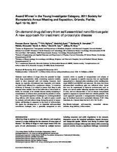
III. T ILE -BASED RUN -T IME A SSEMBLY Advances in technology are redefining the framework in which modern applications are designed and executed. These exigencies present new challenges to hardware designers, developers and development environments. In the face of all the conflicting requirements, reconfigurable hardware in general, and FPGAs in particular are good candidates for hardware platforms. Wireless communications and modern video standards are examples of applications that thrive in flexible environments where environmental factors may demand real-time alterations. Traditional static designs are unable to follow these variations, since they have been optimized for running in specific and invariant scenarios. However, the flexibility of FPGAs opens the window to new implementation strategies capable of adapting dynamically; and relocation and scalability features are the key. An algorithm that can be expressed in hardware in a scalable manner may vary the amount of allocated logic resources, adding or removing modules of the design. The greater the logic resources it uses, the faster it operates at the expense of area. Tile-based assembly is a reconfiguration model that offers a higher degree of flexibility for problems that scale spatially. A graphical example of a tile-based design is shown in Figure 1, where one module is replicated in several positions in an FPGA. Modular designs with a high degree of data parallelism are better suited for scalable implementations. For FPGA deployment, changing the shape of a scalable tiled computation requires the ability to relocate modules throughout the FPGA fabric. The relocation of modules dynamically in an FPGA is a challenge that several researchers have addressed [3][4]. This paper focuses on the case of an embedded autonomous system that benefits from the capability of run-time reconfiguration. In this case, the manipulation of the FPGA bitstream must be done autonomously without the benefit of a powerful desktop computer or vendor tools. For module relocation, the authors of [5] describe a methodology of bitstream splicing that is computationally efficient, and suited for embedded use. Here, a library component in the form of a partial bitstream is manipulated at the bit level. Configuration frame addresses within the component are updated to reflect a displacement to the new target location. It is important to note that this process merely relocates (translates) the spatial location of the component; therefore, it is the designer’s responsibility to ensure that the interconnections between the modules before and after the relocation stage are preserved. For the tiled approach described here, bus macros serve as the input/output portals, and are explicitly placed in chosen positions around the perimeter of the module in a way that they mate directly to adjacent tiles. As a consequence, bus macros need to be included, not only in the perimeter between the static and the reconfigurable design, but also in each reconfigurable module. All modules that are to be interconnected must define the structure of their bus macros in the same way.
Fig. 1.
Replication of one module in a tile-based model
The process implemented is both computationally and memory efficient. In this work, storage is needed for one full configuration bitstream (the initial configuration of the entire design), and one partial bitstream per reconfigurable module. These partial bitstreams are smaller than those produced by the Xilinx PR flow, since they only contain information related to the logic resources of a module, without the header or the tail of a bitstream. The actual number of partial bitstreams needed depends upon the variations of a given design to cope with the heterogeneous nature of the chosen Xilinx FPGA. Architectural restrictions may limit the positions in which a given component can be placed.
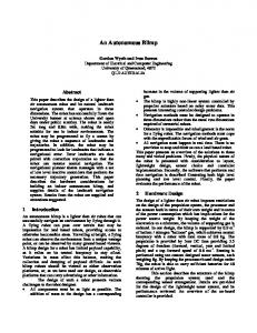
be consulted by the router must be accessible by the router at run time. The newly formed routes are then merged into the bitstream, as illustrated in Figure 2. In this case, Torc is used to compute the new nets. Torc is an open-source infrastructure and tool set for Xilinx FPGA designs that was jointly developed by University of Southern California’s Information Sciences Institute East (ISI East), Virginia Tech, and Brigham Young. The Torc tool-set can (1) read, write, and manipulate generic netlists, (2) read, write and manipulate physical netlists, (3) provide exhaustive wiring and logic information for commercial devices, and (4) read, write and manipulate bitstream packets [7]. Torc is intended as a research and exploration environment for FPGA tool development, yet can be restructured for untethered execution in embedded systems.
IV. M ODULAR -BASED A SSEMBLY Although retaining flexibility and high density, tile-based assembly is not a one-size-fit-all approach; not all computations can be mapped to a systolic array architecture. Oftentimes, a system incorporates components with different shapes and resource requirements. In such cases, a more general assembly method comes into the picture, the module-based assembly. In module-based assembly, components, i.e., modules, are fetched from a library of modules and accommodated within the FPGA to produce a configuration. In such library, modules consist of physically grouped resources that are routed and placed relative to a reference point. Unlike tile-based assembly, this process requires a routing stage to connect module ports, that cannot be perfectly aligned due to variation in modules shapes and sizes. By consulting a device database, inter-components routes are precomputed into routing templates, and used to achieve global routing. In the event of more complex routing scenarios, a light weight router is called to route signals between different components at runtime [6]. Compared to the tile-based approach, the process is also computationally efficient yet requires more memory storage in general. In this work, storage is needed for one full configuration bitstream (the initial configuration of the entire design), and one partial bitstream per library module. These partial bitstreams share the same properties with the ones from the tile-based approach when it comes to size and relocation. The relaxed requirement of ports alignment increases the number of positions per module placement. The router and routing templates, however, require extensive knowledge of the device physical-level connectivity. A connectivity database that can
Fig. 2.
Module-based assembly
V. C ASE S TUDY In contemporary academic design frameworks, only the implementation of one application at a time in an FPGA is considered. In a real system, it is conceivable that there are several independent threads of computation running concurrently, all competing for the same computational resources. This is a common model used in multi-core software systems, and there is no reason why this cannot be extended to FPGAbased systems. In this section, an example image processing system is presented where two independent threads (players) compete for FPGA resources. Both the tile-based assembly and the modular assembly mechanisms are illustrated as a means of building the independent threads. Also, it will be shown that the conceptual gap between algorithm and implementation in the application designers point-of-view is much tighter in this approach than the slot-based Xilinx PR model. When allocating reconfigurable resources, a given player may decide to increase, decrease or maintain the number of modules placed within the FPGA. But the number of possibilities during the reconfiguration, considering more than one design at the same time, grows exponentially at a rate ˆ of [3(number of players)]. In the case study presented here, there are only two players competing for FPGA resources; thus, there are a total of nine possible cases of reconfiguration to consider, summarized in Table I. The Unmodified column represents the fact that a player holds its current allocation with no changes. Columns Increases and Decreases indicate that
TABLE I C ASES OF S CALABILITY WITH T WO P LAYERS
Player 2
Scalability Unmodified Increases Decreases
Player 1 Unmodified Reconfigure Reconfigure Reconfigure
Increases Reconfigure Reconfigure Reconfigure
Decreases Reconfigure Reconfigure Reconfigure
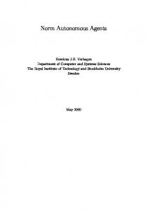
the player modifies its allocation by the addition or removal of modules, respectively. It is possible that while a player is in an unmodified status during the reconfiguration process that changes are still required. Modules controlled by one player may need to be relocated to a new place in the FPGA before another player can perform a resource reallocation. The remainder of this section outlines a scenario in an embedded platform involved in an image processing application. One thread is reconstructing a compressed video stream (Player 1), while the second thread is performing rudimentary image filtering (Player 2). The system is assumed to undergo environmental stress that drives the players to adjust their computational needs. A. First player: Deblocking Filter The last stage of the H.264/AVC and the SVC video encoders and decoders is the deblocking filter (DF). This algorithm reduces blocking artifacts on a video macroblock (MB). These artifacts are generated through the encoding/decoding loop by the previous stages. A MB is composed of a matrix of 1616 pixels of luminance and two matrices of 88 pixels of chrominance. These pixels are organized in groups of 44 pixels, referred to as blocks, numbered from zero to 23. (The first 16 blocks correspond to luminance information, followed by 4 with blue chrominance and the rest with red chrominance). The DF works by filtering eight vertical and eight horizontal edges of a MB. A vertical edge limits the left horizontal boundary of a block in a MB. And the horizontal edge refers to the top frontier of a block. According to the H.264/AVC and the SVC standards [8], it is mandatory that the vertical edges be filtered before the horizontal edges. Therefore, as Figure 3 depicts, any MB depends upon its upper and left MB neighbors. The DF is highly adaptive because it adjusts the filtering operations in accordance to the information contained in the input data. There exist five possible filtering modes (filtering strengths) that vary from 0 to 4. The difference among them is the number of pixels required in the filtering process. A strength equal to 0 means that inputs are not filtered, while a strength equal to 4 modifies three pixels of each input. Strengths between 1 and 3 modify two pixels on either side of the edge. The filtering process is explained in detail in [5]. 1) Deblocking Filter design: Among all the hardware proposals for the state-of-the-art implementation of DF, only a few of them have been designed to support dynamic reconfigura-
Fig. 3.
DF behavior according to the H.264/AVC standard
tion. In regards to scalability, the number of approaches is even lower. Among them, this paper has selected one approach with a high level of scalability. The overall structure is separated into static and reconfigurable regions, interconnected with bus macros. The former reads unfiltered MBs from an external memory, and writes them back once they have been filtered. The latter is composed by three kinds of modules. Depending on how these modules are interconnected, they can form a uni-dimensional array, or a matrix of computation. Two of these reconfigurable modules are responsible for storing and transferring the MBs through the array, whereas the third module processes MBs according to the DF behavior. The structure of the reconfigurable region always follows the same criteria. The first element of a column is a Input Memory (IM) module, and the last one is a Output Memory (OM). The third module, functional unit (FU), may be replicated several times between the IM and the OM, and it is responsible of processing MBs. Figure 4 depicts an example of this design, when a 22 array of FUs has been implemented.
Fig. 4.
Scalable DF design
With regards to the development of this design, it has been conceived to be implemented as part of an embedded system. Furthermore, due to its regular and systolic properties, it has been implemented using the tile-based run-time assembly methodology explained previously. More details can be found in [9]. B. Second player: Video Filters The video filter library consists of four components: a Sobel edge filter, a sharpen filter, a grayscale filter and a solarize filter. In the first two components, image processing is performed by applying horizontal filtering to the image followed
TABLE II K ERNELS OF S OBEL E DGE AND S HARPEN F ILTERS Sobel Horz. Kernel 1 2 3 0 0 0 -1 -2 -3
Sobel Vert. Kernel -1 0 1 -2 0 2 -1 0 1
Sharp Horz. Kernel -1 -1 -1 -1 -9 -1 -1 -1 -1
Sharp Vert. Kernel 0 -1 0 -1 5 -1 0 -1 0
by vertical filtering. The results of the two operations are then summed up to generate the final result. The Sobel edge and the sharpen filtering consist of a convolution operation with a window size of three pixels, computed using horizontal and vertical 3x3 kernels. Table II illustrates the kernels of the two aforementioned modules. Grayscale and solarize filtering processes are much less computation intensive and consist of an averaging operation for the former, and an inversion for the latter. For brevity, the math behind the filtering operations is not shown in this paper. For detailed information, the reader is referred to [10]. The choice of filters is not arbitrary but reflects modules with varying resource requirements and shapes. Arranged by decreasing order of size, the Sobel edge (Filter 1) and sharpen modules (Filter 2) come first, follows the grayscale filter (Filter 3) then finally the solarize filter (Filter 4). Moreover, without loss of generality, the former modules are generated in rectangular shapes, whereas the latter closely match a square shape. Port alignment is not possible between any of the four modules.
die respectively, their modules could have been relocated anywhere in the FPGA, within the restrictions imposed by the resources used in each. Player 1 and Player 2 do not have to be reconfigured at the same time necessarily. Thus, it is possible that Player 1 needs to add or remove resources, but not Player 2 remains as is, or vice-versa. Any of these cases do not differ from the case presented in Figure 5, unless the number of free resources is low. When this happens, modules may need to be relocated in new places in the FPGA before further scaling is possible. An example of this situation is shown in Figure 6. The system has grown until the Player 1 becomes a 2x3 grid, and the Player 2 is formed by four different filters. Considering the situation presented in Figure 6a, if Player 2 needs to increase in size, then it could locate its new modules in the center of the FPGA. However, the challenge arises if Player 1 needs to add one or more modules. As Figure 6b shows, the modules governed by Player 2 must first be relocated before Player 1 is allowed to scale.
C. The game: Competition for resources The following subsection analyzes how the players described above compete for resources in a Virtex-5 XC5VLX110T FPGA. Once the component libraries for the players have been designed, implemented, relocated and configured in a desired region of the FPGA, the entire system may start both applications simultaneously. Referring to Figure 4, the design located in the top region of the FPGA corresponds to the deblocking filter (Player 1), and the design at the bottom is the edge filter (Player 2). Figures 4 and 5 show how Player 1 and Player 2 compete for resources. On the left in both figures depicts the state of the system before the dynamic reconfiguration takes place, whereas the images on the right depict the FPGA afterwards. An application that works in a flexible environment is likely to undergo subtle changes as the application progresses since environmental changes tend to occur gradually. For this reason, and also for simplicity, scalable designs are initially implemented in their simplest form. Following these criteria, Figure 5a shows the most basic structure of each player. Player 1 is formed by a 11 grid, and Player 2 by one filter. When the workload becomes more demanding, players will each compete for more resources. Figure 5b depicts the state of the players after being reconfigured. Player 1 has increased its number of columns and becomes a 21 grid, while Player 2 grows also by an additional filter. Even though Player 1 and Player 2 have grown to the right and to the center of the
(a) Fig. 5.
(b)
Reconfiguration process when both players are scaled
(a)
(b)
Fig. 6. Reconfiguration process when one player is scaled and another relocated
While there are aspects of this “competition” that are somewhat abstract, it is clear that an attempt to accomplish
this with the Xilinx slot-based PR model would be futile. The central difference is that the assembly process relied on by both players in this case study requires a greater degree of spatial freedom and connectivity. Furthermore, since the slot size must accommodate the largest library element in the Xilinx PR flow, efficiency and design density would be lost. While perhaps not perfect, the models of reconfiguration presented in this paper address many of the shortcomings of conventional PR design for the following reasons: • The added flexibility in module placement and interconnectivity not only retains a degree of computational density within the FPGA, it also offers a less constraining model for application designers to work with. • It recognizes that there is likely a degree of multitasking occurring within the FPGA, with more than one design actively competing for resources. • It facilitates a higher degree of adaptability on-demand by means of the relocation and problem scaling properties. • As with most partial reconfiguration strategies, it reduces the bitstream storage requirements since only a copy of each library component is necessary. • It reuses partial bitstreams to scale or reorganize a design. Applications that have a high level of data parallelism and/or systolic behavior may be candidates for tile-based module assembly. Applications that have less structure may benefit from modular assembly. Given that FPGAs are getting larger with each new generation, it is conceivable that applications will have several threads of operation that can be throttled to an extent by the resources allocated in order to favor other threads. As software-only systems have demonstrated, this concept is likely relevant to many application domains, including software-defined radios, video, image processing, and autonomous computing systems. VI. C ONCLUSION
AND
F UTURE W ORK
Existing for several years now and supported by the vendor, current partial reconfiguration flows are limiting with their predetermined connectivity and fixed component size and location, largely reducing the number of application domains that can leverage such assembly trend. Two alternative methods to design assembly are presented in this work: a tile-based and a module-based. The former method is useful if the problem can be formulated as an array of tileable computations with regular connectivity. This offers a higher realizable density and degree of flexibility, compared to the vendor flow. Not all problems can be formulated in this manner. In such cases, the module-based approach offers the highest assembly agility, where random sized and shaped modules are assembled and connected through precompiled routes – at the cost of some loss in design density. All methods are intended for embedded untethered situations where self assembly is required. A case study illustrates one possible use-model where multiple threads compete for a limited pool of resources. Table III summarizes the reconfiguration approaches presented and implemented. In the case study, two image processing tasks reallocate resources to adjust for different computing demands.
TABLE III A C OMPARISON OF RUN - TIME A SSEMBLY S TRATEGIES Assembly Method Xilinx PR Flow
Advantages
Disadvantages
In existence for several years, and supported by the vendor
Component size, location, and connectivity predetermined
Tile-based assembly
Higher degree of flexibility while retaining high density
Size and location flexible, yet pin floorplanning needed so that pieces abut
Modular library place and route
Highest degree of flexibility in pre-compiled module placement and routing
Design is not flattened, leading in a loss of density
Issues The number of problems that can take advantage of this model is small Good for tiled designs, yet difficult to extend to arbitrary shape/function modules Library-based rapid assembly, but requires physical-level connectivity information
The problem of the resource pool management is analogous to similar problems in real-time systems, and is not addressed here. ACKNOWLEDGMENT The authors would like to thank ISI East for their encouragement and support. Part of this work is supported by the Spanish Government and FEDER funds, in the context of Dynamic Reconfigurability for Scalability In Multimedia Oriented Networks project, under contract TEC2008-065846C02. R EFERENCES [1] Xilinx, “Early Access Partial Reconfiguration User Guide (UG208),” 2006. [2] ——, “Virtex-5 FPGA Configuration User Guide (UG191),” August 2010. [Online]. Available: http://www.xilinx.com/support/documentation/user guides/ug191.pdf [3] C. Schuck, M. Kuhnle, M. Hubner, and J. Becker, “A Framework for Dynamic 2D Placement on FPGAs,” in IEEE International Symposium on Parallel and Distributed Processing, 2008, pp. 1 – 7. [4] J. Carver, N. Pittman, and A. Forin, “Relocation of FPGA Partial Configuration Bit-Streams for Soft-Core Microprocessors,” in Workshop on Soft Processor Systems, 2008. [5] A. Otero, A. Morales, J. Portilla, E. de la Torre, and T. Riesgo, “A Modular Peripheral to Support Self-Reconfiguration in SoCs,” in Euromicro Conference on Digital System Design: Architectures, Methods and Tools, 2010, pp. 88 – 95. [6] P. Athanas, J. Bowen, T. Dunham, C. Patterson, J. Rice, M. Shelburne, J. Suris, M. Bucciero, and J. Graf, “Wires on Demand: Run-Time Communication Synthesis for Reconfigurable Computing,” in International Conference on Field Programmable Logic and Applications, 2007, pp. 513 – 516. [7] N. Steiner, A. Wood, H. Shojaei, J. Couch, P. Athanas, and M. French, “Torc : Towards an Open-Source Tool Flow,” in Nineteenth ACM/SIGDA International Symposium on Field-Programmable Gate Arrays, February 2011. [8] I. Richardson, “H.264 and MPEG-4 video compression: Video coding for next-generation multimedia,” p. 102, 2003. [9] A. Otero, T. Cervero, E. de la Torre, S. Lopez, G. Callico, T. Riesgo, and R. Sarmiento, “Run-time Scalable Architecture for Deblocking Filtering in H.264/AVC-SVC Video Codecs,” in to appear at the International Conference on Field Programmable Logic and Applications, 2011. [10] “Getting Started With RoboRealm,” 2005. [Online]. Available: http://www.roborealm.com/help/index.php