Keywords: Modeling, Meta model, Code generation, Business applications ... management facet, a component model to specify application services and so on.
Scaling up model driven engineering – Experience and lessons learnt Vinay Kulkarni, Sreedhar Reddy and Asha Rajbhoj Tata Consultancy Services, 54B, Industrial Estate, Hadapsar, Pune, 411013 INDIA {vinay.vkulkarni, sreedhar.reddy, asha.rajbhoj}@tcs.com
Abstract. Model driven engineering (MDE) aims to shift the focus of software development from coding to modeling. Models being at a higher level of abstraction are easy to understand and analyze for desired properties, leading to better control over software development life cycle. Models are also used to automate generation of implementation artefacts resulting in greater productivity and uniform quality. The focus of the MDE community is largely on exploring modeling languages and model transformation techniques. Not much attention is paid to the issues of scale. Large business applications are typically developed over multiple geographical locations and have a lifecycle running into decades. This puts several additional demands on MDE infrastructure – multi-user multi-site model repository, versioning and configuration management support, change-driven incremental processes etc. We describe our MDE infrastructure, experience of using it to deliver several large business applications over past 15 years, and the lessons learnt. Keywords: Modeling, Meta model, Code generation, Business applications
1 Introduction We have been using model-driven techniques for developing large business applications over the past 15 years. This work began when our organization decided to develop a banking product. One of the key requirements was easy delivery into multiple technology platforms to be able to keep pace with technology advance. Large business applications are typically implemented using distributed architecture. This requires expertise in a variety of technologies such as graphical user interface frameworks, middleware platforms, databases and a variety of programming languages. These applications have to deal with large volumes of data being accessed by a large number of users demanding very high availability. This calls for a good handle on issues such as concurrency management, response time, throughput, optimal batch processing window, and so on. Application architecture is a balancing act as multiple strategies exist to address these issues with different tradeoffs. Different problem contexts demand different application architectures. However, architecture expertise is in short supply, and conceiving the right application architecture and ensuring that it is implemented correctly and efficiently by a large team of developers is a difficult problem. Having a background in compilers, we felt, these varied requirements would be better addressed through a specification-driven
approach wherein specifications abstract out implementation-level details that can be filled in later through code generation. We devised a set of models to capture relevant facets of the desired application architecture, and a high level model-aware language to specify business logic. For instance, a GUI model to specify presentation facet, a database model to specify data management facet, a component model to specify application services and so on. We came up with a unified meta model that enabled us to specify the relationships between the various models and the consistency constraints that govern these relationships. For instance, whether a GUI screen is able to display data corresponding to input and output parameters of a service being invoked from the screen; whether all attributes of a persistent class hierarchy are mapped onto columns of database tables; whether relationships between persistent classes are mapped to primary and foreign key attributes of relevant tables and so on. Compiler of our high level language treats the various models as its type system thus ensuring consistency between code and models. Large size of application required sub-teams performing specialized tasks such as creating analysis models, refining analysis models with design details, specifying business logic, transforming models and business logic to code, testing the implementation, deploying into the desired deployment set-up etc. These sub-teams need to share a unified view of the models in order to ensure that different models are consistent with each other, and business logic is consistent with the models. To achieve this, we developed a centralized multi-user repository for storing models. We used a 3rd party source code control system to store business logic specifications and used the model repository to store links between these specifications and models. With this in place, the simplest way to achieve a unified view is to have everyone work off a single copy. However, this enforces everyone to be in lock-step thus sacrificing flexibility in development. To balance this concern, we developed a component abstraction to support the notions of private and public workspaces, and devised a protocol for synchronizing them. Large outsourced projects typically have an onsite and an offshore development team. Most of the projects that used our approach were of this nature. The geographical separation places an additional requirement on repository synchronization. This was addressed by enhancing the protocol for local synchronization suitably. Large software development engagements are typically delivered in phases where each phase constitutes a well-defined baseline in the project lifecycle. Even after final delivery, the project continues to evolve due to variety of reasons such as introduction into new geographies, complying with new regulatory frameworks and exploiting technological breakthroughs. To address this need, we developed robust and comprehensive versioning and configuration management capabilities for application specifications – both models and business logic. In many business applications, it is critical to have short turn-around times for changes – especially in maintenance phase. This requires all development / maintenance processes to be change-driven i.e. effort required to implement a change should be proportional to the size of the change. We engineered our MDE processes and tools supporting them to be incremental in nature.
App layer meta model
GUI layer meta model Window * has
*
1..* has *
UIAttribute mapsTo 0..1
Attribute
implements
*
* destination
1
1
mapsTo
*
Class
opens * has
1 has *
* 1..*
*
UIClass
0..1
*
source
Operation
Button 0..1
* realizes
0..1
call
*
Task *
* precedes
Db layer meta model
0..1
Association
*
1
1 has
has *
1 has
*
*
Column
Attribute * ofType 1
Table
0..1
0..1
mapsTo
1..*
0..1
Key *
composedOf
DataType
* has 1..*
Process
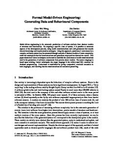
Fig. 1. A subset of the unified meta model
Over the past 15 years, we have delivered several solutions in several business verticals. There is a large amount of commonality across the solutions belonging to a vertical. In absence of a mechanism to capture this commonality, one is forced to introduce a new feature and / or a bug fix at several places. This is effort intensive and error-prone. We discuss the need for managing commonality and variability at model level, and present our ideas. Section 2 gives an overview of the model-driven development approach we have been practicing. The MDE infrastructure and processes we developed to scale this approach to the demands of industry practice are discussed in sections 3 and 4 respectively along with our experience and lessons learnt. Section 5 discusses the need for supporting commonality and variability in MDE infrastructure in order to scale to the demands of industry practice. Section 6 concludes with a short discussion.
2 Our Model-driven Development Approach We started with the objective of cleanly separating the functional concerns from the technology concerns in order to enable application developers to concentrate on business requirements without having to worry about implementation-level details such as persistence, transaction processing, large dataset handling and concurrency. We used UML[1] to model application functionality and extended UML meta model where required to model various aspects of interest. Business applications can be seen as comprising of three broad classes of functionalities, namely online, batch and reports. In this paper, in the interest of space, we restrict the discussion to online functionality only. Online functionality is typically implemented using a layered architecture consisting of presentation layer, business logic layer and data manager layer as shown in fig 1.
We used UML class diagrams to capture business entities and their relationships, UML use-case diagrams to describe business scenarios, and UML activity diagrams to describe process flows. We extended UML class models with additional properties and associations in order to capture architectural information, such as classes that make up a message, classes that need to be persisted in a database, classes that need to be displayed on a GUI screen, operations that need to be deployed as services having transactional behaviour and attributes that are mandatory. We designed a modelaware high-level language (Q++) to specify the business logic. Q++ treats the extended UML class models as its type system, provides constructs for navigating model associations, and allows for declarative specification of errors and exceptions. Also, the language abstracts out details such as memory management and exception handling strategy. Model-aware nature of Q++ guarantees that business logic specifications will always be consistent with the models. We extended UML to specify the presentation layer in terms of special abstractions, namely windows and windowtypes. A windowtype specifies a pattern such as a form screen, a list screen, and so on. A window is an instance of a windowtype. It specifies which data elements of which business entity to display using which controls and which buttons should invoke which business services and/or open which windows. Our presentation layer model was independent of the implementation platform except for the event code. We extended UML to specify relational database schemas and complex database accesses. Object – relational mapping was realized by associating object model elements to the schema model elements, i.e. class to table, attribute to column, association to foreign key etc. We defined a Query abstraction to provide an object façade over SQL queries with an interface to provide inputs to, and retrieve results from the query. We used a slightly modified SQL syntax in order to bind input/output parameters. We came up with a unified meta model to specify the above mentioned models and their relationships. Fig. 1 highlights the associations spanning these models. These associations help keep the three specifications consistent with respect to each other and thus ensure that the generated platform-specific implementations are also consistent [2]. For example, the association Button.call.Operation can be used to check if a window is capable of supplying all the input parameters required by an operation being called from the window. Similarly, we were also able to model other facets such as batch functionality, reports etc. From these various models and high level specifications, we were able to generate a complete application implementation.
3 MDE Infrastructure Model driven engineering needs, at a minimum, a means for creating models of interest and a means for transforming those models into software development life cycle (SDLC) artefacts. UML has become a de facto modeling language in industry. General practice is to fit all modeling requirements into abstractions provided by UML and its extension mechanisms such as stereotypes. These models are then
Object
0..* instanceOf
instance Of Level 1
Meta meta model instance Of
Level 2
Meta model instance Of
Level 3 Information system or user model
Fig.2. Modeling levels
Association srcRoleName : String tgtRoleName : String srcCard : String tgtCard : String isSrcOwner : Boolean isTgtOwner : Boolean
1 type
instanceO Class f 0..* source name : String 1 isAbstract 0..* target : Boolean 1 instanceOf
instanceOf
Attribute
name : String 1 attribute dataType : String 0..* 1 0..* inheritsFrom
Fig.3. Reflexive meta meta model
transformed into code fragments that need to be completed and put together manually. In contrast, we generate complete applications from models. Therefore, we capture all facets of business applications as models. As these models are the principal artefacts in SDLC, they must be first class entities, intuitive and closer to the problem domain. We found that by force-fitting all models into UML or UML stereotypes, these important properties are lost. In our experience, no two projects had exactly the same requirements on MDE infrastructure. At the same time, the infrastructures were not entirely different either. There was a large amount of commonality across these infrastructures. There is a need for a good composition mechanism to address the commonality and variability in MDE infrastructure. 3.1 Modeling Infrastructure 3.1.1 Meta Modeling An information system can be seen as collection of parts and their relationships. A model of an information system is a description of these parts and relationships in a language such as UML. The modeling language itself can be described as a model in another language. The latter language is the meta model for the former as shown in Fig 2. We use a reflexive modeling language that is compatible with OMG MOF [3] to define models at all levels. A model at each level is an instance of the model at the previous level. The model at level 1, the meta meta model, is an instance of itself. The meta meta model shown in Fig. 3 is the base model. It is the schema for describing meta models. The meta meta model is capable of describing itself, i.e., it can model itself. Everything in a model is an object. An object is described by its class. A class is specified in terms of a set of attributes and associations. An object is an instance of a class that has attribute values and links to other objects as specified by its class. Since everything is an object, a class is also an object that is specified by another class called metaclass. In Fig. 3, the class class is a metaclass which is an instance of itself. A meta model specification consists of: a model schema which is an instance of the meta meta model, a diagramming notation to edit its instance models, and a set of
derives 0..* 1
0..* contains
Configuration
1
0..*
Partition
0..* derives 1
0..* 0..* contains Partition Version
has
1..* 1
contains 0..*
Object
Fig. 4. Meta model for versioning and configuration management
constraints and rules to specify consistency and completeness checks on its instance models. We provide a reflexive modeling language-aware generic model editor for creating models as well as their meta models. We use OCL [4] to specify wellformed-ness constraints over models. We provide a diagram definition workbench to define visual notations and map them onto meta model elements. Having a meta modeling framework enabled us to extend modeling languages as per need. 3.1.2 Multi-user Repository Large sized applications require sub-teams performing several specialized tasks. These sub-teams need to share a single version of truth in order to ensure that different models are consistent with each other and business logic is consistent with the models. We developed a central repository for storing models that provided concurrent access to multiple users. Multi-user operation requires support for transaction and concurrency management. Models being the core artefacts in MDE, these features are critical to maintain integrity of models. Choice of our own filebased storage mechanism for models would have meant having to implement robust transaction and concurrency management features ourselves. Instead, we chose industry-strength relational database as a storage mechanism which provides a robust implementation of these critical features. We do support a file-based storage mechanism, but, for single user operation only. 3.1.3 Versioning and Configuration Management To manage complexity and enable concurrent development, we developed a Partition abstraction using which a large model can be decomposed into a set of related units. We developed a Configuration abstraction using which a set of compatible Partitions can be put together with a guarantee of completeness. Fig. 4 shows our meta model for versioning and configuration management. R Conradi and B Westfechtel have published a detailed survey and classification of various version models [5]. Our versioning model provides extensional versioning with configuration as the recursive composition structure and Partition as the versioned entity, with in-built composability constraints. Partition Partition is a container for model elements such as objects, properties and associations. After creation, an object is placed in a Partition and carries the identity of the Partition. Models are versioned at the level of a Partition. Versions of compatible Partitions are assembled, within a configuration, to represent model of the
complete system. An object belongs to a Partition and is versioned with the Partition. Thus, an object gets the version number of its container Partition, but two versions of an object will always have the same ObjectId. When an object is contained in a partition version, its properties and the associations owned by it are also contained in that partition version. Partition is a typeless construct, i.e. an instance of any meta object can be placed in a Partition. Associations can either be between objects belonging to the same Partition or different Partitions. An inter-partition association establishes a relationship between two partition versions and it belongs to the partition version to which the owner object of the association belongs. A partition version guarantees change isolation i.e. changes made to the objects in one version are not visible in other versions. Conceptually, a new version of a Partition contains copies of the objects of the version from which it is derived. Thus, a Partition enables concurrent development of different parts. Configuration Configuration is a container for assembling partition versions. It provides the context for creating inter-partition associations. Two configurations can share a partition version. Thus, configuration versions are designed to support sharing, while partition versions are designed to support change isolation. Also, a configuration can contain other configurations. Configuration enforces completeness through the “ownership” property of associations – if a configuration contains a Partition X having an object O that owns the association A, then the configuration must contain a Partition Y having the object at the destination end of the association A. For example, the association calls from function to function is owned by the caller function and hence a configuration that only contains caller functions is incomplete. Diff and Merge We provide a facility to compare („Diff‟) and merge models contained in two partition versions or two configurations. Two versions of an object are compared based on their ObjectIds and in terms of their property values and associations. Often, comparison of two objects by themselves is not of much value unless it is done in the context of its associated objects. Such a context is also necessary while merging versions of an object. In general, in a given model, some objects play the role of primary objects and others play the role of companion objects. For example, in the OO model, Class is a primary object and Attribute is a companion object. Two Attributes should only be compared in the context of the Classes to which they belong. Such context sensitive comparison and merge operations can be performed by specifying object-association graphs or patterns. An example pattern for comparing classes in two partitions could be: „Class-attribute-Attribute‟ and „Class-operationOperation‟. 3.2 Model Transformation Infrastructure We transform models into a variety of SDLC text artefacts such as code, deployment descriptors, user documentation and makefiles. We developed a scripting language specially designed to traverse a model and emit code. The language treats meta model
Q++ code
Design strategies
Model to PB translator
GUI layer in PB
Q++ to C++ translator
App logic layer in C++
Model to C++ translator
DM layer in ProC
Query to ProC translator Model to JSP translator Extended UML models
Query code
Q++ to Java translator
GUI layer in JSP
Model to Java translator
App logic layer in Java
Query to JDBC translator
DM layer in JDBC
Fig. 5. Scattering and tangling in code generation
as its type system, provides special constructs for navigating associations, and common imperative constructs such as if-else, for and while loops. The language also enables specification of text to be generated in a wysiwyg manner. We found that this language was sufficient for all our model-based code generation requirements. Even though we use a number of meta models, they are not related to each other in a transformational sense. Rather, they have associations between them and a set of constraints to ensure the models are consistent with respect to each other. The closest use-case for model-to-model transformation we found was that of object – relational mapping, and even here the mappings were rather simplistic. 3.3 Building Blocks As can be seen from Fig. 5, different code generators are needed to deliver the same business functionality on different technology platforms. This is despite these code generators sharing a great deal of common functionality and differing mostly only in the use of primitives offered by the target technology platform e.g. syntax differences of programming languages and data type differences of databases. Even while delivering identical business functionalities on identical technology platforms, we ended up implementing different code generators in order to deliver onto different architectures such as synchronous and queue-based messaging. Similarly, choice of different design strategies resulted in different code generators. In the case of design strategies, the problem was exacerbated even further. Since many design strategies cut across several architectural layers, changing an existing design strategy or adding a new design strategy required modifications to multiple code generators in multiple places. Ensuring complete and consistent implementation of such a change became difficult as it required thorough knowledge of all the concerned code generators on the part of a tool implementer. This problem became more acute as the number of variants of the code generators grew. The tangling of model-based code generators, as shown in Fig. 5, is due to lack of separation of the various concerns, namely, technology platform, architecture and design strategies, and the cross-cutting nature of design strategies. An improved architecture for model-based code generation is where the models are successively
refined by application of the various design strategies to a stage from where a platform specific implementation can be realized through a simple task of models to text transformation. As the platform-specific code generators are independent of design strategy related issues, the same model-to-text transformation specifications can be reused with different design strategies and vice versa. This separation of concerns enables a tool variant to be viewed as a composition of design strategy and technology platform aspects of choice. We developed Building Block abstraction to support this separation of concerns and composition. A building block encapsulates a choice along one of these dimensions. A code generator is the desired hierarchical composition of building blocks [6]. The process of model-driven code generation is realized through a post-order traversal of the building block hierarchy in three sequential steps, namely, Instantiation, Transformation and Weaving. The instantiation step stamps out models and merges them [7]. The transformation step transforms models into code snippets and generates weaving specifications for composing them [8]. The weaving step composes the generated code snippets by processing the weaving specifications. We could organize multiple variants of a code generator as different compositions of building blocks into a family as follows: Commonality across variants can be specified using a set of common building blocks Functionality specific to each variant can be specified using a set of variant building blocks Composable nature of building blocks enables realization of the desired family member as a composition of suitable common and variant building blocks
4 Model-driven Development Process 4.1 Component-based Development Large business applications require large development teams. Typically, development effort is partitioned along functional modules that have high internal cohesion and low external coupling. In absence of explicitly stated dependencies, such a partitioning may introduce spurious dependencies that can lead to integration problems. For instance, a consumer module should not refer to internal implementation-specific details of its supplier module. This becomes more critical in model-driven development where the development artifacts comprise of both models and code, as a result, spurious dependencies can be introduced either in model, code or both. In our experience, this turned out to be a significant issue during development of our banking product which had a peak team size of around 150. We introduced a component abstraction to manage these dependencies at model and code level. A component specifies its interface in terms of model elements such as Classes, Operations and Queries. The consumer-supplier relationship between components is explicitly modeled through depends association between the components. A component can only use the model elements specified in the interface of the components it depends upon. As Q++ is model-aware, we can honour these
Check for well-formedness constraints and consumer-supplier dependencies
4
Configuration
1 keptInSync
MSP
Directory
1 own 1
0..* refer 0..* s Partition
Modeling workspace of supplier component 3
Workspace 1 has 1 0..* Component
C_Workspace keptInSync
1..* 1
kept in sync
1
Release
Fetch
1..* M_Workspace
Modeling workspace of consumer component
kept in sync
Workspace for sharing models (MSP)
Coding workspace of supplier component
Coding workspace of consumer component
CSP
0..* depends
Fig. 6. Meta model for workspaces
Release
5 Workspace for sharing code (CSP)
2 Release
Fig. 7. Synchronizing components
model-level dependencies automatically in code as well. A component has two associated workspaces, a model workspace and a code workspace as shown in Fig. 6. The model workspace is a configuration comprising of own Partition and Partitions of the components it depends on. In a component workspace, one is only allowed to change the contents of own Partition. As workspaces provide change isolation, a consumer component is not immediately affected by the changes introduced in its supplier components. A special workspace, configuration MSP of Fig. 6, is provided for exchanging models between components. A (supplier) component releases its model to this special workspace for sharing, from where its consumer components pick it up as shown in Fig. 7. Model well-formedness constraints and consumersupplier dependencies are then automatically checked in the consumer component workspace. A similar workspace, directory CSP of Fig. 6, is provided for sharing code between components. Components are allowed to share code only after they share their models. Model-awareness of Q++ ensures consistency across consumer-supplier components at code-level as well. The process is realized through a set of roles, each responsible for performing a set of well-defined tasks on a component in a workspace. A role essentially identifies a set of logically coherent process steps. For instance, all modeling related tasks are grouped into the modeler role, all coding related tasks are grouped in the programmer role, all workspace synchronization related tasks are grouped in the manager role, all setup related tasks are grouped in the administrator role. Explicit modeling of interfaces and dependencies provided better control over integration of components being developed independently. This enhanced structure was used to compute change impact leading to significantly reduced testing effort. 4.2 Geographically Distributed Development Large business applications are developed in a distributed manner over multiple sites. Ideally, in a repository-centric development approach, it should be possible for distributed teams to connect to a central database. However, we found several issues in performance intensive actions such as diagram editing when connected over WAN or web. We decided to replicate the repository at multiple sites and synchronize it using a well-defined protocol. One of the alternatives was to use background database
synchronization products. However, synchronization of models needs manual supervision which renders such products unsuitable. We devised our own synchronization protocol which is an extension of the one shown in Fig. 7. The „workspaces for sharing models‟ from different sites were synchronized using a meta model pattern based diff-merge process (discussed below). This enabled individual teams to continue working in their respective local workspaces undisturbed. We ensured globally unique identifiers for model elements across sites to avoid clashes. 4.3 Delta-driven Processes The performance of various model processing operations such as model validation, diff/merge, model transformation and code generation tends to deteriorate with increasing model sizes. This in turn affects turn-around times for change management. Ideally, these operations should only consume time that is proportional to the size of the change and remain unaffected by the total size of the model. We devised a pattern-based approach for implementing incremental execution of common model-driven development processes such as model transformation, model comparison and merging, model validation, model export and code generation. We also developed a meta model for recording changes and integrated it into the model repository for efficient change processing. Models are well-structured graphs, and many model processing operations can be formulated in terms of graphs. Also, most models are processed in clusters of related elements; for instance, a class, its attributes and operations are usually processed together. Each such cluster has a primary element that identifies the cluster; for instance „Class‟ in the above example. We used meta model patterns to specify such clusters with the root identifying the primary element of the cluster. We then specified the model processing operations in terms of these patterns. For example, when we want to compare class models of two UML models, we want the comparison to be conducted on clusters of model elements centered around class objects; in pattern model terms we want to treat class as the primary object, with its attributes, operations and associations making up the rest of the connected elements of the cluster. In execution terms, a diff operation can be seen as being invoked repeatedly for each matching root element of the pattern from both the source and target models. Fig. 8 shows the meta model for recording model changes that occur in a model repository. We call this model a delta model. A Delta is a record of a single change; it has a timestamp property that records the time of the change and an opCode property that records the operation causing the change, namely, one of ADD/MODIFY/DELETE. ObjectDelta records changes to objects; PropDelta records changes to properties; and AssocDelta records changes to associations. ObjectDelta has an association to Object to identify the object that has changed; it also stores the ID of the object (ID is required because that is the only way to identify an object that has been deleted from the repository). PropDelta has an association to Property to identify the property that has changed, and records two values – new and old (if any). AssociationDelta has an association to Association to identify the association that has changed, and two links to ObjectDelta corresponding
oldValue newValue Property
PropDelta
0..1
0..1 PropValue
* 1
Class
Object
ObjectDelta
Delta
ObjectID
Timestamp opCode
end2 1 *
Association
1 end1 *
AssocDelta
MOF model
Fig. 8. Delta model
to the two end objects. The associations between ObjectDelta, PropDelta and AssocDelta mirror the associations between Class, Property and Association in the meta meta model, and thus record the same structure. We devised an algorithm that, given a model pattern, computes the impacted root objects from a given model and its delta model for the set of changes recorded in a given time period. Thus, we could identify which root objects in the model have changed in a given change cycle and apply the necessary model processing operations only on these root objects. This resulted in minimal code generation for the model changes. We used „make‟ utility which is time-stamp sensitive, and hence subsequent compilation – build – test – deploy processes are also incremental.
5 Commonality and Variability We discovered that different solutions in the same business domain were not exactly alike even for identical business intent. With toolset providing no means to capture commonality and variability, application development teams had to resort to copypaste of application specifications. As a result, what should have been a variant of an application ended up being a separate application thus leading to maintenance and evolution problems. These problems compounded with every new solution being delivered. We extended our model-driven development approach to support the family concept [9]. We have different meta models to describe different layers of application as shown in Fig 1. We enhanced these meta models to support family concept so as to impart configurability and extensibility properties to the generated applications. We illustrate this in the context of application layer. Application layer specifies business logic in terms of Class, Attribute and Operations. Fig. 9 depicts the meta model for imparting configurability and extensibility at the granularity of class. This meta model is an extension of the application layer meta model highlighted in Fig 1 as follows: - Classification of Attributes into fixed, free and delmod. A Class contains fixed attributes in all situations whereas free attributes are specific to a situation. Attributes tagged delmod represent situation-specific deletions and/or modifications. - An Attribute can conform to different types.
Classification of Operations into Configurable and Concrete: The former have situation-specific behavior whereas the latter have fixed behavior in all situations. - Body of a Configurable operation is a Template with well-defined extension points (TxtnPoint) where different behaviors can be plugged in. An extension point is specified in the form of an interface invocation – a factory returns the appropriate object (Txtn) that implements the extension. - Extending existing behavior amounts to providing a new extension (Ov) for existing extension points or defining a new template (Ox) for the operation being extended or both. - Cv depicts situation-specific class definition. - A situation helps select the desired variant of a class from multiple alternatives [10] Thus, the above meta model enables modeling of a family of classes wherein each family member serves the same intent in a specific situation. By making the above information available as metadata, application can switch from one known situation to another at run-time. A new situation is handled by adding a new row in the metadata tables. Not all situational adaptations can be handled at run-time though, for instance, addition of a new behavior extension (Ox or Ov) would need recompilation (followed by redeployment). Similarly, definition of a new class altogether, as an extension to existing functionality, cannot be handled at run-time. However, the meta model enables a new situation to be added to the existing set of configuration alternatives. We extended other application layer meta models on the similar lines. -
6 Discussion We have used model-driven techniques to deliver more than 70 business critical applications over the past 15 years. For instance, a policy administration system we developed for a large insurance company comprises of ~75 components, ~4500 classes, ~100K model elements, and ~2M lines of higher level language specifications. Size of the generated application is around 20M lines of C++ code. This application is operational for the past 12 years with 1500 person-years worth effort having gone into it so far. First delivery of system had a peak team size of around 250 distributed onsite and offshore. Design and Construction phases of application development witnessed more than double productivity improvements – principally due to generation of solution architecture related code from models. For instance, database schema definition, primary-key based data access methods such as Create, Modify, Delete, Get and Exists and methods for navigating along class associations were completely generated for classes marked as Persistent in the model. Our Query abstraction enables specification of complex database accesses in a simple extension of SQL syntax. We translate a query into a class having Execute method which is essentially a wrapper for the SQL statement and handles the peculiarities of RDBMS and data access mechanisms such as ODBC, JDBC and DAO. Treating Query as a class enables type safety when invoked from application logic layer. A query can be annotated to be a cursor query or a paging query which leads to generation of additional methods, for instance, Open, Fetch and Close in case of the former, and GetNext and GetPrevious in case of the latter. On similar lines, we generate solution architecture specific code for business logic and presentation layers. However, onsite and offshore nature of work needed significant manual effort for coordination. This effort coupled with inadequate support for testing and requirement capture phases ate into productivity benefits due to model-based code generation. Several enhancements have been delivered since with total team size not exceeding 50. Overall effort savings of around 20% have been realized over the operational span of the system. In our experience, having a robust central repository and repository-centric processes proved to be a significant advantage for managed evolution as all stakeholders had access to a single version of truth. By hosting our repository on an industry-strength RDBMS, we could delegate transaction management and concurrency control responsibilities to the RDBMS enabling us to support a large number of concurrent users. Most MDE tools available wouldn‟t have scaled up to our needs as they are based on single-user file-based storage for models. These tools do provide basic mechanisms to organize models into containers and code into directory structures. However, every project team has to build the superstructure to keep model containers and their code counterparts in sync, and to keep different model containers in sync with each other. Our MDE infrastructure has a pre-defined meta model to define components, workspaces and a synchronization protocol as discussed in section 4.1 thus obviating the need for building the superstructure for each project. Most MDE tools delegate versioning and configuration management responsibilities to file-based version control tools. As models are also stored in files, these files can also be managed by the same versioning tool. However, as the
structure inherent in the model is not visible to the versioning tool it cannot exploit the structure for fine-grained version control. Also, as the versioning tool is oblivious of model content, it cannot provide semantically meaningful configuration management. Project teams need to build these features on top. Our MDE infrastructure has a pre-defined versioning and configuration management meta model (ref section 3.1.3) thus obviating the need for building this superstructure for each project. Most MDE tools do not come with a change model inbuilt. As a result, the onus of determining what has changed in a model, what impact the change has on other model and code artefacts, and how to propagate the change correctly to all the impacted artefacts lies entirely with the developer. This is an error-prone and effort-intensive activity. Our MDE infrastructure has a pre-defined delta meta model (ref section 4.3) and a pattern-based change propagation mechanism relieving the developer of this burden. Delta-driven processing has brought down complete build time for a component of the insurance policy administration system application from about 60 mins to an average 6 mins. From our experience, the above issues are critical for scaling MDE to the demands of enterprise scale applications. Going by literature, it appears MDE community isn‟t paying enough attention to these issues. As MDE begins to gain industry acceptance, we believe such issues are going to become more critical.
References 1. Unified Modeling Language, http://www.omg.org/spec/UML/2.2/ 2. Vinay Kulkarni, R. Venkatesh, Sreedhar Reddy: Generating Enterprise Applications from Models. OOIS Workshops 2002: 270-279 3. Model Object Facility, http://www.omg.org/spec/MOF/2.0 4. Object Constraint Language, http://www.omg.org/spec/OCL/2.2 5. R. CONRADI and B. WESTFECHTEL. 1998. Version Models for Software Configuration Management. In ACM Computing Surveys, June 1998. 6. Vinay Kulkarni, Sreedhar Reddy: An abstraction for reusable MDD components: modelbased generation of model-based code generators. GPCE 2008: 181-184 7. MOF™ Query / Views / Transformations, http://www.omg.org/spec/QVT/1.1/Beta2 8. MOF Models to text Transformation Language, http://www.omg.org/spec/MOFM2T/1.0/ 9. D E Parnas: Designing software for ease of extension and contraction. ICSE 1978: 264 – 277 10.K. Czarnecki and C. H. P. Kim: Cardinality-Based Feature Modeling and Constraints: A Progress Report. In OOPSLA‟05 International Workshop on Software Factories (online proceedings), 2005