Published in "The Journal of Foraminiferal Research 37(3): 270-276, 2007" which should be cited to refer to this work.
SCANNING ELECTRON MICROSCOPE IMAGES OF UNCOATED MICROFOSSILS: APPLICATIONS, PERSPECTIVES AND LIMITATIONS SILVIA SPEZZAFERRI*, CHRISTOPH NEURURER, CLAUDIUS PIRKENSEER
AND
BERNARD GROBETY
University of Fribourg, Department of Geosciences, Geology and Paleontology, Chemin du Muse´e 6, 1700 Fribourg, Switzerland
http://doc.rero.ch
ABSTRACT
ornamentation in live and fossil ostracod valves are viewed as important taxonomic and/or ecological features. These observations, made possible by high-resolution SEM imaging, produced enormous progress in our understanding of past assemblages and environments. The subsequent development of the environmental scanning electron microscope (ESEM) has allowed scientists to view specimens and processes in their natural state. A specimen viewed in this microscope does not need to be in high vacuum or coated with material like gold (Scott and others, 1993). With the ESEM, it is possible to image organisms while wet. At present, however, ESEM imaging is not commonly used, and sometimes this instrument is not easily accessible and/or available for micropaleontological studies. Digital images taken using conventional reflected light microscopes and light photography are not a suitable replacement for SEM-generated images, as they generally do not show sufficient resolution, even when taken as composite, multi-layer, stereographic images (Knappertsbusch, 2002). Thus, there is a need for an alternative method to obtain high resolution and clear SEM images of uncoated microfossils. Presently, two types of electron sources are commonly used in electron microscopes to obtain such images: thermionic emission and field emission (FEG) type guns. Both sources are compatible with ESEM. Since 1996, good quality images of uncoated, primary-type, planktonic foraminifera have been obtained by B. Huber at the Smithsonian Institution using a thermionic SEM (TSEM) set at a low kilovoltage electron gun potential, an increased scan rate, and digital frame averaging to avoid the problem of electron charging. Images of Mesozoic and Cenozoic, primary-type specimens from the Smithsonian Institution collections are posted on the Smithsonian website. TSEM and an ESEM images of uncoated, primary-type, Mesozoic, planktonic foraminifera from the Smithsonian and other museums are posted on the on-line Mesozoic Planktonic Foraminiferal Taxonomic Dictionary (http://www.chronos. org), and numerous TSEM and ESEM images of uncoated, Paleogene, primary-type specimens have been published by the Paleogene Planktonic Foraminiferal Working Group (e.g., Liu and others, 1998; Olsson and others, 1999; Pearson and others, 2006). The initiatives of the Mesozoic and Paleogene planktonic foraminiferal working groups have made the availability of type specimens for SEM documentation essential. The senior author, currently a member of both working groups, has recently faced the problem of imaging holotypes of planktonic foraminifera that are stored in museums. The policy of many museums forbids gold coating of holotypes, even for scientific purposes (e.g., the Museum of Natural History of Basel). In some cases, it is
We present a recently developed method using a field emission scanning electron microscope (FEG) to view and photograph microfossil specimens that are not coated by conductive material. The FEG microscope provides high electron flux and offers the option to capture images at low beam voltage. Balancing incident energy with absorbed energy from the detector leads to charge-free images of non-conductive material. As an example of the application, we show images of planktonic foraminifers and ostracods obtained with this method and compare them with those obtained on the same specimens after gold coating. The method is particularly useful for illustrating holotypes, neotypes and topotypes of microfossils when an environmental scanning electron microscope is not available. INTRODUCTION Pioneers of micropaleontology, such as Fichtel and Moll (1798) and d’Orbigny (1846), based their taxonomy on drawings of specimens. At the time, the only mechanical aid for capturing images of microfossils was the ‘‘lucernal microscope,’’ which projected an image onto a frosted glass screen (the ‘‘camera lucida’’ or drawing prism), which permitted simultaneous observation of both the microfossil and the drawing plane (Ro¨gl and Hansen, 1984). With the development of electron microscopy, micropaleontologists could obtain higher resolution images of many microfossil groups, including benthic and planktonic foraminifers, ostracods, calcareous nannoplankton, radiolarians and diatoms. From the 1970’s until recently, scientists produced excellent SEM images of type materials, but were limited to drawings of holotypes or neotypes (e.g., Luterbacher and Premoli Silva, 1962; Caron, 1976). This was because, up to that time, there was no guarantee for the safety of specimens subjected to a high-voltage electron beam. Additionally, the need for conductive material in the process forced the coating of specimens with gold or carbon. This concern still exists today, as it is known that coating may damage the specimens during sputter coating or obscure small features (e.g., small-sized pustules, etc.). Studies of microfossils proceeded parallel to the development of more sophisticated SEM and studies of living specimens in their natural environment or laboratory cultures. For example, by comparison with living organisms, the function and significance of structures in fossil planktonic foraminifers, such as spines, pustules and keels, are viewed as evolution-driven adaptations to changing paleoecological settings (e.g., Hemleben and others, 1989). Likewise, muscle scars, hinge elements, sieve plates and *Correspondence author. E-mail:
[email protected]
1
http://doc.rero.ch
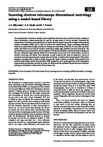
FIGURE 1. Simplified representation of the beam-energy dependence in electron microscopy. Modified after Reimer (1998). See text for definitions of symbols.
not possible to take holotypes to SEM facilities outside the Museum (e.g., the Museum of Natural History of Paris), and not all museums have SEM facilities. Such policies and the lack of an ESEM urged the development of an efficient method of imaging specimens that cannot be coated. However, image quality from the FEG SEM is better than that obtained from uncoated specimens with standard thermionic emission SEM. The advantages are the better resolution, as well as the higher gun brightness, which results in a higher probe current. The resolution, r, attainable in SE mode depends on the probe size, dP (beam diameter), and the escape depth of the electrons, de, which for secondary electrons is mainly a function of material parameters such as average atomic number and density:
For conventional acceleration voltages (f.ex. 10–20 kV), the sum of the two cross-sections is smaller than 100%, which results in negative charging (e.g., more electrons enter than escape the sample). The negative charge shields the sample and deflects the primary beam. Decreasing beam energy, E (5 decreasing voltage), will increase the sum of the crosssections and for a certain value, E2, it will exceed 100%, resulting in positive charging. Such charging, however, has no shielding effect on the primary beam. The balance level is shown in figure 1 at E2, where electron input is equal to electron output. Imaging of insulating samples is thus possible without coating for beam energies below E2. For very low beam energies (E 5 E1), which are not usually attainable by current microscopes, the cross-sections decrease again and the sum falls below 100% (lower limit E1). The limit E2 may be determined experimentally and is in the range between 1 and 4 KeV (Reimer, 1998). Quantitative values for calcite, however, are not available.
r~ dP 2 zd e 2 Þ1=2 : The minimum attainable beam size depends on the probe current: I P therm ! d P
8=3
and
I P FEG ! d P
2=3
METHOD
:
After testing different methods, the following procedure was found to be the most efficient: a conductive tab (polycarbonate with a layer of conductive glue 30-mm thick) was placed on an aluminum SEM sample holder. The sample holder was sputter coated with a thin layer of gold (10 nm). The coating of the sample holder must be precisely 10 nm and is an essential requirement for a correct application of this method, as it guarantees enough conductivity for imaging and, at the same time, does not prevent the safe placement of the specimens, which remain glued to the support. A thicker layer has been found to interfere with the proper attachment of the specimen. Specimens were placed on the sample holder and then analyzed with a SEM (FEI XL30 Sirion FEG) using a beam voltage of 1 kV and a probe current of ,60 picoAmperes. At that low electron flux, the amount of primary electrons is equal to the amount of electrons absorbed by the detector and the specimen. These settings lead to charge-free imaging. Usually electron-specimen interaction is different for each microfossil, so the electron flux has to be adapted. The advantage of this method compared to that previously
For a beam diameter #0.1 mm, the maximum probe current (beam intensity) for a given probe size is up to three orders of magnitude higher for a field emission gun than for a conventional thermionic gun. In turn, for a given probe current, the minimum probe size is one to two orders of magnitude smaller for a field emission gun, which results in a similar improvement in resolution (Reimer, 1998). An essential requirement for visualizing uncoated specimens is to understand charging effects that occur close to the sample surface. In particular, electrons entering the sample surface must be in balance or in excess relative to electrons escaping from the same surface. In SE mode, both secondary and backscattered electrons contribute to the image. The ratio between electrons entering and electrons leaving the sample is a function of the respective cross–sections. In general, the cross-sections for secondary (d) and backscattered electrons (g) leaving the sample are inversely proportional to the beam energy E: d ! E {0:8
and g ! E {2 : 2
used and described in Caron and Spezzaferri (2006) is that specimen irradiation is lower, and the quality of the photographs is suitable for publication. The operator of the SEM should take into account the increased time needed for adjustments. For comparison, the same specimens were coated with 40 nanometers of gold, observed and imaged with a standard beam voltage of 20 kV at a probe current of 15 nA, which is ,250 times the value used in the uncoated treatment.
scar images (Plate 3, figs. 1c–6c) are equally good in resolution. PERSPECTIVES Presently, taxonomic studies of foraminifera tend to follow biologically guided or evolutionary based classifications, using wall textures rather than their general morphologies (e.g., Hemleben and others, 1991; Olsson and others, 1999). Therefore, it is very important to have SEM documentation of species and their holotypes in order to build strong and consistent species concepts. When SEM images of holotypes are required and museums do not give permission to coat them with conductive material, in the absence of an ESEM, the application of this new method may provide excellent and clear images. Figures 9a–c of Plate 2 show, for the first time, the SEM images, obtained by applying this new method to the topotype of Thalmanninella gandolfii (Luterbacher and Premoli Silva). The topotype was described by Luterbacher and Premoli Silva (1962) and illustrated only by drawings in their figures 3a–c of Plate 19. The specimen is presently deposited at the Museum of Natural History of Basel, and we were not permitted to coat it with gold. The images are clear, and the characters typical of Thalmanninella are shown as described in Gonzalez-Donoso and others (2007). In particular, we can observe an umbilicoconvex profile typical of this lineage, the intraumbilical supplementary apertures of the first chambers of the last whorl, the periumbilical ridges (at least in the first chambers of the last whorl) and the peripheral keel dividing into two raised branches on the spiral and umbilical sides.
http://doc.rero.ch
APPLICATIONS To illustrate the possible applications of the method, we have chosen two groups of microfossils: planktonic foraminifera, for their complex wall textures (e.g., Olsson and others, 1999; see Spezzaferri and Spiegler, 2005 for an overview of fossil planktonic foraminifers), and ostracods, for their convex/concave morphology, which provides a different challenge to obtaining good resolution images. The challenges provided by the two microfossil groups show the potential of the method. Planktonic foraminiferal species have been chosen according to their different wall textures (Plates 1, 2), following the criteria of Olsson and others (1999). Comparison between images of gold-coated and uncoated specimens indicates that the resolution and quality of images obtained with the non-coating technique are comparable and, in some cases, better than those obtained with the standard coating technique (Plate 1). Figures 1 and 2 show an uncoated specimen of Globigerina bulloides. The details of its wall texture are perfectly visible, including the smooth wall texture between spine pedestals. Figures 3 and 4 of Plate 1 show the same specimen after gold coating. In this case, the smooth wall texture is not as clear as in figure 2. Figures 5 and 6 of Plate 1 show an uncoated specimen of Globigerinita juvenilis, revealing the details of its microperforate texture with minute pustules, with a resolution remarkably similar to that obtained after coating of the specimen (Plate 1, figs. 7–8). Globigerinoides obliquus with a cancellate and spinose wall texture is shown in figures 9–12 of Plate 1. In particular, figure 11 of Plate 1 (detail of the wall texture of an uncoated specimen of G. obliquus) clearly shows spines inside the supplementary aperture. The same image (Plate 1, fig. 12), taken after gold coating of the specimen, does not show this detail, suggesting that coating may have obscured and/or damaged this feature. Plate 3 shows three species of ostracods, Cytherelloidea jonesiana (figs. 1a–c; 2a–c), Hemicyprideis helvetica (figs. 3a–c, 4a–c) and Pterygocythereis ceratoptera (figs. 5a–c, 6a–c), with their muscle scars coated and uncoated, respectively. Figure 1b of Plate 3 shows the outside of the right valve of an uncoated C. jonesiana, which possesses a flat morphology and is as clear as the image of the same side of the valve after coating (Plate 3, fig. 2b). Overall, more concavo-convex species, like H. helvetica and P. ceratoptera, seem to have an opposite response. Concavity is better represented in coated specimens than in uncoated specimens, giving a better impression of depth within the valve. Uncoated and coated muscle
LIMITATIONS This method presents some limitations due to changes in conductivity within the same specimen. These changes in conductivity may be produced by impurities, infillings or remnants of glue and also by the general morphology of the specimens. However, they do not seriously compromise good imaging. In strongly convex or concave specimens, some areas of the shell may appear dark compared to the rest of the test. Tilting or rotating the specimens to a different angle with respect to the detectors can solve the difficulty. Dark areas can also be caused by the presence of holes, apertures or strong ornamentation, all of which results in a series of striae or dark areas on the test surface. These characteristics can be seen in the specimens illustrated in Plate 1, figures 9 (spiral view of Globigerinoides obliquus) and 11 (detail of the supplementary aperture on the spiral side of G. obliquus); in figures 1–4 of Plate 2 (the spiral sides of Globigerinoides sacculifer, Globorotalia menardii, Pulleniatina obliquiloculata and Sphaeroidinellopsis kochi); and in Plate 3, figures 3b–4b and 5b–6b (the exterior surfaces of H. helvetica and P. ceratoptera, respectively). In the case of S. kochi (Plate 2, fig. 4), the coarse pores seem to be responsible for the dark striae. Furthermore, the depth of field may be reduced because of the lower tension and lower working distance (Plate 3, figs. 5b, 6b). 3
http://doc.rero.ch PLATE 1 1–4 Globigerina bulloides d’Orbigny. ODP Leg 160, Sample 973A-5H-CC, Eastern Mediterranean: 1, 3 5 spiral view, 2, 4 5 detail of the wall texture. 5–8 Globigerinita juvenilis (Bolli), ODP Leg 115, Sample 706-3H-1, 34-36, Indian Ocean: 5, 7 5 spiral view, 6, 8 5 detail of the wall texture. 9– 12 Globigerinoides obliquus Bolli, ODP Leg 160, Sample 973A-5H-CC, Eastern Mediterranean: 9, 10 5 spiral view, 11–12 5 detail of the wall texture.
4
http://doc.rero.ch PLATE 2 1, 5 Globigerinoides sacculifer fistulosus (Schubert), ODP Leg 115, Sample 706-3H-1, 34-36, Indian Ocean. 2, 6 Globorotalia menardii (Parker, Jones and Brady), ODP Leg 115, Sample 706-3H-1, 34-36, Indian Ocean. 3, 7 Pulleniatina obliquiloculata (Parker and Jones), ODP Leg 115, Sample 7063H-1, 34-36, Indian Ocean. 4, 8 Sphaeroidinellopsis kochi Caudri, ODP Leg 115, Sample 706-3H-1, 34-36, Indian Ocean. 9a–c Thalmanninella gandolfii (Luterbacher and Premoli Silva), topotype.
5
http://doc.rero.ch PLATE 3 1a–c, 2 a–c Cytherelloidea jonesiana (Bosquet), Rupelian, Southern Upper Rhine Graben, Central Europe: 1 5 Uncoated; 2 5 Coated. 3a–c, 4a–c Hemicyprideis helvetica (Lienenklaus), Rupelian, Southern Upper Rhine Graben, Central Europe: 3 5 Uncoated; 4 5 Coated. 5a–c, 6a–c Pterygocythereis ceratoptera (Bosquet), Rupelian, Southern Upper Rhine Graben, Central Europe. 5 5 Uncoated; 6 5 Coated. On all figures, a 5 inside of right valve, b 5 outside of right valve, c 5 details of the muscle scar.
6
FICHTEL, L., and MOLL, J. P., 1798, Testacea Microscopica Aliaque Minuta ex Generibus Argonauta and Nautilus ad Naturam Delineata et Descripta: Anton Pichler, Wien, v. XII, 123 p. GONZALEZ-DONOSO, J.-M., LINARES, D., and ROBAZYNSKI, F., 2007, The rotaliporids, a polyphyletic group of Albian-Cenomanian planktonic foraminifers: Emendation of Genera: Journal of Foraminiferal Research, v. 37, no. 2, p. 175–186. HEMLEBEN, C., SPINDLER, M., and ANDERSON, O. R., 1989, Modern Planktonic Foraminifera: Springer-Verlag, NY, 363 p. ———, MU¨HLEN, D., OLSSON, R. K., and BERGGREN, W. A., 1991, Surface texture and the first occurrence of spines in planktonic foraminifera from the early Tertiary: Geologische Jahrbuch, v. 128, p. 117–146. KNAPPERTSBUSCH, M. W., 2002, Stereographic virtual reality representations of microfossils in light microscopy: Paleontologia Electronica, v. 5, no. 3, 11 p., http://palaeo-electronica.org/paleo/ 2002-1/light/issue1-02htm. LIU, C., OLSSON, R. K., and HUBER, B. T., 1998, A benthic paleohabitat for Prepararotalia gen. nov. and Antarcticella Loeblich and Tappan: Journal of Foraminiferal Research, v. 28, no. 1, p. 3–18. LUTHERBACHER, H. P., and PREMOLI SILVA, I., 1962, Note pre´liminaire sur une revision du profil de Gubbio, Italie: Rivista Italiana Paleontologia e Stratigrafia, v. LXVIII, no. 2, p. 253–288. OLSSON, R. K., HEMLEBEN, C., and BERGGREN, W. A. (eds.), 1999, Atlas of Paleocene Planktonic Foraminifera: Smithsonian Contributions to Paleobiology, v. 85, 252 p. PEARSON, P. N., OLSSON, R. K., HEMLEBEN, C., HUBER, B. T., and BERGGREN, W. A., 2006, Atlas of Eocene Planktonic Foraminifera: Cushman Foundation for Foraminiferal Research Special Publication No. 41, 513 p. REIMER, L., 1998, Scanning Electron Microscopy: Physics of Image Formation and Microanalyses: Springer-Verlag, Heidelberg, 527 p. RO¨GL, F., and HANSEN, H. J., 1984, Foraminifera Described by Fichtel and Moll in 1798: A Revision of Testacea Microscopica: Ferdinand Berger and So¨hne, Wien, 143 p. SCOTT, P. C., POPE, R. K., SCHEETZ, R. W., RAY, R. I., WAGER, P. A., and LITTLE, B. J., 1993, Advantages of environmental scanning electron microscopy in studies of microorganisms: Microscopy Research and Techniques, v. 25, p. 398–405. SPEZZAFERRI, S., and SPIEGLER, D., 2005, Fossil planktonic foraminifera (an overview): Pala¨ontologisches Zeitschrift, Stuttgard, v. 79, no. 1, p. 149–166.
CONCLUSION A new method to obtain electron microscope images has been developed and illustrated. The method requires the application of a very thin gold coating (10 nm) on the sample holder before attaching the specimens to the holder and the use of low voltage and beam current (about 250 times less than the standard voltage for SEM imaging). Image quality obtained with this method is comparable between coated and uncoated specimens, although, for uncoated specimens, the depth of field and the contrast are lower. Nonetheless, relatively clear, high-resolution images are obtained despite the limitations of the method. The treatment has great potential for the illustration of holotypes, neotypes and topotypes when museums refuse permission to coat specimens and ESEM is not an available option.
http://doc.rero.ch
ACKNOWLEDGMENTS Thanks to the members of the Mesozoic and Oligocene Planktonic Foraminiferal Working Group for fruitful discussions on taxonomy. Thanks also to Arne Ziems and Michael Knappertsbusch (Natural History Museum Basel) for providing the topotype of Thalmanninella (Rotalipora) gandolfii and holotypes of other Cretaceous foraminiferal species whose much-needed illustration urged the development of this method. This method has been developed with the FEG SEM of the Department of Geosciences, University of Fribourg. REFERENCES CARON, M., 1976, Re´vision des types de Foraminife`res planctoniques de´crits dans la re´gion du Montsalvens (Pre´alpes fribourgeoises): Eclogae Geologicae Helvetiae, v. 69, no. 2, p. 327–333. ———, and SPEZZAFERRI, S., 2006, Scanning electron microscope documentation of the lost holotypes of Mornod, 1949: Thalmanninella reicheli and Rotalipora montsalvensis: Journal of Foraminiferal Research, v. 36, no. 4, p. 374–378. D’ORBIGNY, A., 1846, Foraminife`res fossils du basin Tertiare de Vienne (Autriche): Gide et Comp. Libraires Editeur, Paris, 312 p.
7