Scenario-based Configuration Management for Flexible Experimentation Infrastructures Ferm´ın Gal´an∗ , Jorge E. L´opez de Vergara† , David Fern´andez‡ and Ra¨ul Mu˜noz§ ∗ Telef´ onica
I+D Emilio Vargas 6, 28043 Madrid, Spain † Departamento de Ingenier´ıa Inform´atica Escuela Polit´ecnica Superior, Universidad Aut´onoma de Madrid Av. Francisco Tom´as y Valiente 11, 28049 Madrid, Spain ‡ Departamento de Ingenier´ıa de Sistemas Telem´aticos Escuela T´ecnica Superior de Ingenieros de Telecomunicaci´on, Universidad Polit´ecnica de Madrid Av. Complutense s/n, 28040 Madrid, Spain § Centre Tecnol` ogic de Telecomunicacions de Catalunya Av. Canal Ol´ımpic s/n, 08860 Castelldefels (Barcelona), Spain Email:
[email protected], jorge.lopez
[email protected],
[email protected],
[email protected] Abstract—Configuration management is a key issue in flexible networking experimentation infrastructures (i.e., testbeds). However, manual procedures have several drawbacks (such as high time consumption in tedious and mechanic operations or the probability of introducing human errors). Moreover, intertestbed scenario reutilization (i.e., the same network configuration replicated from one testbed to another) is difficult to achieve. In order to solve this limitations, automatic mechanisms are desirable in order to make testbeds profitable tools for their users. Our work describes one of such approaches, defining a model-driven methodology for automatic testbed reconfiguration. It is based in a high-level testbed-independent model (thus being applicable to any testbed in general) which is used to describe desired experimentation scenarios. Those scenarios are then particularized to testbed-specific models for automatic deployment and management by model-based tools. The paper also provides practical use cases applying the methodology in two different situations (VNUML-based virtual testbeds and the R GMPLS-enabled optical networking ADRENALINE testbed ) thus assessing the feasibility and generality of our solution. Index Terms—Networking testbed, scenario deployment, configuration management, model-driven management, Common Information Model.
I. I NTRODUCTION In the context of this work, a testbed can be defined as a controlled infrastructure (maybe located in a laboratory or spread worldwide) used to experiment with networking systems (e.g., protocols, architectures, etc.) under conditions that resemble the ones in real networks (thus differencing from network simulation). In research, testbeds have been used from the very beginning (as a matter of fact, the Internet itself was in its origin a testbed to assess the feasibility of packet switching technology) and still being valuable tools in the current hot topics (such as optical and wireless networking contexts, or new approaches in business objectives driven infrastructure This paper is being supported by the Business Oriented Infrastructure (BOI) research initiative within the Business Support Systems (BSS) unit at Telef´onica I+D.
management). In addition, from an industrial point of view, testbeds are very valuable platforms to test and debug network services and software early prototypes, in order to drive the development of new solutions in IT and telco markets. Finally, a testbed can be very useful for students in colleges and engineering schools, so they can complement what they have learnt in theoretical lessons with practical skills working on (almost) real networking environments. Each testbed is unique, since it is developed by different engineers addressing different objectives. However, they share some common characteristics. A first basic classification can be established between reconfigurable and non-reconfigurable testbeds. A reconfigurable testbed or flexible testbed (such as R Emulab [1], PlanetLab [2], ADRENALINE testbed [3] or recent global initiatives as GENI [4] or FEDERICA [5]) can implement different experimentation scenarios (defined as a networking context i.e. network topology, service and process configuration, etc. provided by the testbed in which some experiment is conducted in a given timeframe) using the same physical infrastructure. The more different scenarios a testbed can implement, the more flexible (and useful) the testbed is. On the contrary, non-reconfigurable (or non-flexible) testbeds are short-lived infrastructures built to test a particular idea or concept (they usually are proof-of-concepts in research contexts) and dismantled after that. Another classification is between IP-based and not IP-based testbeds, being the former the most representative case due to the predominant position of IP networks nowadays (and the one to which our work is oriented). In order to achieve reconfigurability, many testbeds rely on human interaction, either by direct interaction with the testbed equipment (like in ADRENALINE) or using a decoupled bunch or infrastructural services (like in PlanetLab or GENI). This fact has severe drawbacks: time consumption, high human error probability, need of specific knowledge on low-level reconfiguration technology and scalability. In
addition, although some testbeds (like Emulab) implement reconfiguration systems, they use to be ad-hoc mechanisms, lacking the appropriated abstraction level in order to be generalized to other testbeds apart from the one in which they were developed. This paper proposes a model-driven mechanism to reconfigure testbeds, providing automation and thus overcoming the problem of manual reconfiguration. In particular, the proposal is based on a testbed-independent model of the desired scenario from a high-level perspective (so the user of the testbed can concentrate on its specific research, industrial or educational purpose). This model is then automatically transformed to a testbed-specific model (so the same high-level model can be reused in different testbeds with little effort). The testbed-specific model is finally processed by model-based tools in order to perform the needed management operations to deploy the desired scenario. In this sense, our work is a contribution to the configuration management of networking testbed infrastructures1 . This work is partially based on our previous research on model-driven configuration management for testbeds [7]. While that article introduced a preliminary version of the testbed-independent model (just a draft diagram) and outlined some of its usage scenarios, the present paper goes further, providing a thorough description of the modeling alternatives, describing the semantics of the classes and associations involved in the testbed-independent model and clarifying with examples their application cases. The rest of the paper is structured as follows. First, the problem of manual scenario deployment in reconfigurable testbeds is addressed in Sect. II. Then, the solution to the problem is described in Sect. III, detailing the proposed methodology and its main element (the testbed-independent model), after a discussion of the different modelling alternatives. Next, Sect. IV describes the practical application of the methodology and provide details of testbed-specific models for two specific testbed use cases: virtual-based testbeds and optical networking testbed, stressing the role of the model-based tools (VNUML and ADNETCONF, respectively). Finally, Sect. V closes the paper with the conclusions and future work lines. II. P ROBLEM S TATEMENT Although, as stated in the introduction, each reconfigurable testbed is unique in nature, the basic experimentation workflow is common, composed of several steps. Firstly, a user designs a networking scenario where the tests will be performed. This scenario usually includes a specification of the network topology (number of nodes, its properties and its interconnections) 1 The International Telecommunication Union (ITU) has defined configuration management as the functions to “exercise control over, identify, collect data from and provide data to NEs [network elements]” [6]. In testbed context, the provisioning sub-topic (“procedures which are necessary to bring an equipment into service, not including [physical] installation”) is specially relevant, consisting the service in our case on experimentation scenario set up), along with the status and control sub-topics (“capability to monitor and control certain aspects of the NE on demand”, in our case being those aspects the ones related with scenario provisioning).
and a specification of the processes (i.e., programs, services, etc.) to be run in each node (each one with its corresponding configuration). Next step is to deploy the scenario in the testbed infrastructure, configuring its physical elements in the proper way. Once the scenario is set and ready, a user can conduct experiments (launch commands, execute programmed tests, collect results, etc.). Finally, when tests are over, the scenario is undeployed, releasing assigned testbed resources (i.e., physical nodes, network addresses space, etc.) so new scenarios can be deployed. Deployment (and undeployment)2 are critical steps, especially in the case of heavily used testbeds that need to be quickly reconfigured between experiments in order to maximize their usage. Manual reconfiguration is the simplest procedure, but introducing commands and configurations manually in the different testbed devices has several important drawbacks. Firstly, it is a high time-consuming task because too much time is spent performing tedious and mechanics operations. Secondly, reconfiguration needs specific knowledge regarding the testbed technology not related with the goal of the testbed itself (testbed users are supposed to be experts in the experimentation field the testbed addresses but not in the low-level testbed enabling technologies). Third, humans tend to make errors typing commands and writing configurations (usually very subtle and difficult to detect), which may produce a wrong deployed scenario, thus corrupting the experimentation results. In the case of multi-user testbeds, errors can be even more problematic, when a wrong deployment conflicts with already deployed scenarios, maybe even belonging to a different user. Finally, manual reconfiguration is poorly scalable because the bigger the scenario to be deployed is, the more time it takes to be configured and more likely to introduce errors. In addition to these problems, scenario reutilization across testbeds can be very difficult. Inter-testbed scenario reutilization can be interesting in two cases. First, complex experiments can need several complementary testbeds, each one devoted to a particular aspect of the implementation or idea under test (e.g., a first testbed based on virtual machines to test and debug the software code implementing a given service, and a second testbed composed of a hardware platform where the final version of the software is stressed and tuned in near-toreal condition previously to using it in a production network), but needing the same set of scenarios to get coherent results. Second, it could be interesting to develop a set of “reference” network scenarios (e.g., NSFNET-based topologies [8]) useful for a wide range of experiments (and maybe shared among researchers and educators in some public repository). Note that some testbeds (maybe the best known case is Emulab [1]) provide an automatic deployment mechanism. Although they can overcome the problems of manual deployment, they use to be too coupled with the specific testbed and lacks in generality, so limiting inter-testbed scenario 2 In the following, we only refer to deployment for the sake of simplicity, although undeployment is implicitly considered.
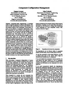
reutilization. Therefore, a more general solution is required, as the one described in the next section. Finally, although the problem that we are addressing in configuration management is related with network simulation (e.g. ns2 [9]), the scope of this paper is focused on networking testbeds. Note that simulators consider also networking scenarios, but such scenarios are run in discrete events software engines, not involving the actual configuration of infrastructure. Additionally, test definition scripting languages (such as TTCN-3 [10]), are out of the scope, because of although they are very useful to describe test cases (including different control flows depending on the test outcome) they do not provide the means to configure the testbed scenario where these tests actually run. III. P ROPOSED S OLUTION A. Methodology The proposed methodology is based on modelling the desired networking scenarios at two abstraction levels, as shown in Fig. 1. The first level corresponds to a testbed-independent model, which describes the desired network topology from a high-level perspective, without considering its deployment aspects (e.g., which physical device will host each node). The second level is a testbed-specific model, which completes the high level model with those deployment details for the specific testbed. The testbed-specific model is derived automatically from the testbed-independent model, using automatic transformation tools. They take the testbed-independent model as input and add information regarding how it is actually deployed in the testbed. Therefore, transformation tools require a description of the testbed environment (e.g., number and attributes of physical nodes, etc.). It is worth noting that testbed parameters are the same for all input networking scenarios; they are only modified when the testbed capabilities change (e.g., a new physical element is added to the testbed infrastructure). This approach, based on two modelling abstraction levels and automatic transformations between them, is quite similar to the one proposed in the Model-Driven Architecture (MDA) [11] in the context of software engineering. The testbedindependent scenario model plays the role of Platform Independent Model (PIM) and the testbed-specific plays the role of Platform Specific Model (PSM). In the following, we will use the terms TIM and TSM to refer to testbed-independent and testbed-specific models respectively. The actual scenario deployment is performed by testbed specific model-based configuration management tools. The tool takes the TSM as input and performs automatically the corresponding deployment actions, interacting with the testbed physical elements. Examples of such tools are VNUML (described in Sect. IV-A), ADNETCONF (Sect. IV-B) or the Emulab “swapping-in” engine. The proposed approach overcomes all the problems described in Sect. II. First, the utilization of automatic procedures (in model transformation and deployment) solves the problem of time-wasting (because of the work is done by the tool
on behalf of the user), human error occurrence (since human interaction is avoided) and scalability (the processing logic implemented by the software tool is the same no matter the size of the networking scenario). Second, the model architecture abstracts the user from specific technological details of the testbed, so the user can concentrate in the design of the networking scenario, without bearing in mind testbed implementation details. The TIM provides complete isolation (because of it does not include any testbed specific information) while the TSM includes details regarding deployment but, even in that case, the difficult low-level configuration management actions are performed by the deployment tool processing that TSM. Finally, inter-testbed scenario reutilization is achieved, because of the existence of a testbedindependent model (Fig. 1 shows an example considering the same scenario used in three different testbeds). Although developing the corresponding TIM-to-TSM transformation would imply an additional effort, this is only performed once during the testbed lifetime so it can be considered as part of the testbed setup process (as, for example, the wiring of the equipment and the installation of operating systems). It is worth noting that only one TIM-to-TSM transformation module is developed for each testbed (able to process whichever TIM is used as input). The different alternatives to implement the aforementioned models are presented in next subsection (actually, experimentation scenarios are instance models conforming those models)3 . Note that in order to be interpreted by automatic tools, models have to be specified using formal languages. B. Modeling Approaches Several approaches can be used to model the networking scenarios at two abstraction levels. To select the most appropriate alternative, we have first considered the most relevant modelling approaches in terms of completeness and transformability. Completeness is referred to the ability of the model to represent any networking scenario in any existing or future testbed, whereas transformability is related to the capability of the model to be transformed into another model to deal with a specific testbed. Taking these ideas into account, the first approach, as stated before, is to use MDA. Other possibilities are the use of XML technology and ontologies. Each approach is explained below, providing their advantages and drawbacks. The eXtensible Markup Language (XML) [13] is a language proposed by the W3C and highly supported by the industry. With this language, users can define their own tags to describe structured data. These tags are defined by using either Document Type Definition (DTD) or XML Schema, which describe the way in which tags can appear in a document. Currently, many tools usually use XML for the syntax of their configuration files. In fact, both VNUML and ADNETCONF configuration files are based on XML (see Sect. IV). In these 3 Considering the same terminology used in the OMG’s layered metamodeling architecture [12].
Testbed 1 parameters
Desired scenario
Testbed 2 parameters
Testbed 3 parameters
TIM to TSM1 Transformation
TIM to TSM2 Transformation Testbed-independent scenario model (TIM)
TIM to TSM3 Transformation
Fig. 1.
Testbed specific scenario models (TSM)
Deployment tool (e.g., VNUML)
Testbed 1 (e.g. virtual)
Deployment tool (e.g., ADNETCONF)
Testbed 2 (e.g. ADRENALINE)
Deployment tool (e.g. Emulab engine)
Testbed 3 (e.g. Emulab)
Model-based automatic configuration management methodology
cases, XML has been used to identify the parameters that have to be used when deploying a network scenario. One interesting property of XML files is that they can be transformed by means of transformation languages such as eXtensible Stylesheet Language Transformations (XSLT) [14] or XQuery [15]. With these languages, a transformation can be defined that translates an input XML document into another document. There are many tools that can interpret such languages to transform documents. Then, these transformations could be used to translate from a platform independent testbed configuration file to a platform specific configuration (e.g. VNUML, ADNETCONF). However, the description of such transformations is usually complex. On the other hand, XML is not a good language for modelling. DTDs or XML Schema files just provide a description of how a document has to be formatted with a set of tags, providing the syntax of these documents. Nevertheless, the semantics of these tags is hidden. Precisely to deal with the semantics of the information, ontologies provide a way to formally describe a set of concepts and properties and the relationships between these concepts [16]. Ontologies have recently gained relevance thanks to the Semantic Web, existing different tools and APIs to work with them. Given the heterogeneity of ontologies, many works have provided methods to map information from one ontology to another. In fact, in [17] ontology mappings are proposed to solve the interoperability of management information models. Another useful characteristic of ontology languages is that they can specify logic rules in the information itself. These logic rules can be used to enforce the behaviour of the defined information. They have also been proposed to define translation rules among concepts [18], or even to find which networks comply with concrete requirements [19]. This last application can be useful to check if a scenario can be deployed in a set of resources (i.e., a testbed). If this modelling approach is used in our work, a platformindependent testbed ontology should be defined, as well as the ontologies and mapping rules for each platform. Later, these platform-specific ontologies should also be transformed
in the testbed configuration files, adding more complexity to this solution. Last but not least, the Model-Driven Architecture [11], proposed by OMG, provides a framework to model systems that enables the separation of the functional specification and its implementation on a specific platform. For this, two model levels are defined. One of these levels is named Platform Independent Model (PIM) and provides a model of the system structure and functionality, avoiding technical details of the specific platform where the system can be deployed. The other level is named Platform Specific Model (PSM), and provides a way to represent the system with elements that are specific of the platform where the system is deployed. Both models are defined by leveraging other OMG technologies such as the Unified Modeling Language (UML). This modelling approach fits very well in our work, as explained in the previous section. Of relevant importance to MDA is the notion of model transformation. A PSM is the result of applying a set of transformation rules on the elements in the PIM, and it represents the system with specific artefacts of the deployment platform. Alternatively, a reverse process can be applied, generating the PIM from a PSM, useful to extract design information from an implementation. To perform these transformations, a specific standard language has been defined by OMG called Queries/Views/Transformations (QVT) [20]. Several tools currently claim to be QVT-compliant, but they only provide partial implementations. Therefore, at this time this solution is not well supported by existing software. C. CIM-based Testbed-independent Model Given the different alternatives, the testbed-independent model is based on the DMTF’s Common Information Model (CIM) [21] because this enables the application of any of the approaches described in the previous subsection. Apart from its “native” representation in MOF (Managed Object Format) textual language, CIM has an XML representation [22], but it is also represented in UML, and there is a UML profile for CIM [23]. There are also some works to represent CIM in ontology languages [24][25][26]. Then, any of the approaches
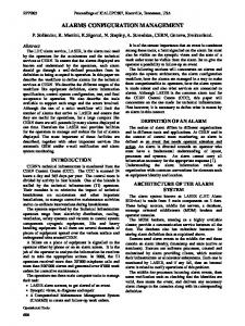
can be used, bearing in mind the advantages and drawbacks explained before. As a matter of fact, the set of classes and relationships used to define the TIM could be considered a testbed CIM profile, although it should be noted that not all the classes are defined in existing CIM schemas. In this sense, the TIM is similar to the IP interface profile described in [27], but focused on scenario models for networking testbeds. Consequently, the TIM considers interconnection links (not only interfaces) and a more complete node model (including forwarding, static routes and extensible network-related functionality). The TIM is composed of two parts. First, a TIM Core which is common to all use cases and defines basic IP networking concepts, like topology, addressing, static routing, etc. Second, optional user-defined TIM Extensions that define a coherent set of network functionalities (services, processes, applications, etc.) executed by the nodes in the network (e.g., a TIM GMPLS Extension for GMPLS networking testbeds). Fig. 2 shows a class diagram of the TIM Core and one example of TIM Extension (the TIM GMPLS Extension). CIM prefix has been taken out from CIM schema classes for brevity. Regarding the TIM Core: • The central classes are ComputerSystem and TIM LinkConnectivityCollection to model nodes and links respectively, thus describing the topology. • ComputerSystems belong to a TIM TestbedScenario, which models the scenario as a whole. • The ComputerSystem interfaces are modeled through the IPProtocolEndpoint class, which IP addresses are described with IPAssignmentSettingData instances (as a matter of fact, there are two subclasses, one for IPv4 addresses –StaticIPAssignmentSettingData– and one for IPv6 ones –TIM StaticIPv6AssignmentSettingData). • A ComputerSystem may have static routes (modeled with TIM NextHopAddressesIPRoute). • Forwarding is implemented using ForwardingService (it is assumed that nodes not hosting a ForwardingService will not forward packages, as corresponds to endsystems). • Each IPProtocolEndpoint is associated through the TIM MemberOfLink aggregation to the link it belongs to. An interface belongs to exactly one link (except for loopback interfaces, that are not associated to any link). The MaxConnections property in TIM LinkConnectivityCollection can be used to specify a maximum number of interfaces (e.g., two to model a PPP link). • Optionally, link QoS characteristics can also be specified, which is very interesting in some cases (e.g., link emulation), through TIM TransmissionCharacteristics objects associated to the link. Each instance of this class encapsulates a set of QoS constraints (delay, loss probability, etc.) for interfaces belonging to the link (specifying the link through the TIM LinkTransmissionElement and, optionally, TIM LinkOrigin and TIM LinkDestination if the caracteristics are asymmetrical).
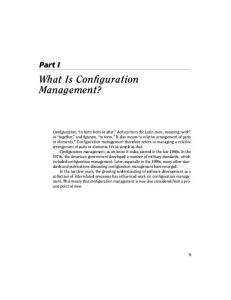
Regarding TIM Extensions, they define a set of services as derivates of the CIM Service class, which nodes may run. For example, the TIM GMPLS Extension shown in Fig. 2. defines the five services that are needed to implement a GMPLS control plane (see Sect. IV-B). Except for the simplest cases (like the ForwardingService included in the TIM Core), services have an associated configuration (e.g., OspfTeConfiguration and LrmConfiguration), which can be quite complex (including other associated classes). One of the keys of using CIM is that, given its broad coverage of network management information, it has been relatively easy to find equivalent (or semantically close enough) CIM classes or associations for each concept needed in our problem domain. Only for a very few concepts (the ones pre-fixed with TIM ) it has not been possible, considering in this case the derivation from CIM classes with a close semantic: • TIM TestbedScenario. Although CIM includes a Network class, the TIM TestbedScenario (derived from the former) has been introduced in order to model the specialized semantic of an scenario in the networking testbed (as a particular kind of network). • TIM StaticIPv6AssignmentSettingData, due to the existing StaticIPAssignmentSettingData does not consider IPv6 addresses. • TIM NextHopAddressedIPRoute, because of the existing NextHopIpRoute from it derives does not allow a direct specification of the route destination (it uses the AssociatedNextHop, which is not appropriated in some situations) so the NextHopAddress field needs to be introduced. • TIM LinkConnectivityCollection. CIM does not include an interconnection link (logical) model, although the ConnectivityCollection (from this class is derived) has a close semantic as “group of protocol endpoints of the same type”. • TIM TransmissionCharacteristics. In this case, no similar QoS modelling concept has been found in CIM, so this class derives directly from SettingData (a rather abstract class). Note that instead of considering the complete CIM Schema, the TIM (defined as a CIM profile) is only based on a subset of relevant concepts. Firstly, because it could be overwhelming to consider and include every management object from each Common Model. Secondly, because only a subset of concepts is needed to solve the problem of automatic deployment in reconfigurable testbeds and the inclusion of more than necessary would be overengineering the problem. D. TIM Scenario Example In order to illustrate the model described in the previous section with a particular instance model (namely sample model), let’s consider a very simple (for the sake of simplicity and briefness) network model scenario conforming to TIM. It consists of two hosts linked by a PPP link executing two dialoguing OSPF-TE entities (in a GMPLS networking context), as shown in Fig. 3 using the usual UML semantics (e.g. instance names underlined and the instanceOf relationship
TIM GMPLS Extension
TIM Core
TIM_NextHopAddressedIPRoute DestinationMask: string DestinationAddress: string PrefixLength: uint8 AddressType: uint16 {enum} NextHopAddress: string
TIM_TestbedScenario 1
*
HostedCollection
RsvpTe
SnmpAgent
Service
*
SystemComponent
w *
HostedRoute 1 * ComputerSystem
* ConnectivityCollection
Olrm
OspfTe *
Lrm
*
1 OspfTeConfiguration
HostedService 1
1
[…] 1
TIM_LinkConnectivityCollection MaxConnections: uint16 1 TIM_LinkTransmissionElement w *
0..1 HostedAccessPoint
0..1
*
ForwardingService ProtocolType: uint16 {enum}
w * * IPProtocolEndpoint
TIM_LinkOrigin
0..1
TIM_LinkDestination
Fig. 2.
[…]
ElementSettingData
* IPAssignmentSettingData
*
0..1
StaticIPAssignmentSettingData 0..1
LrmConfiguration
ForwardsAmong
TIM_MemberOfLink
TIM_TransmissionCharacteristics DelayMean: uint64{units} DelayDeviation: real32 DelayDistributionFunction: uint16{enum} LossProbabilityValue: real32 LossProbabilityCorrelation: real32 CorruptionProbability: real32 CorruptionProbabilityCorrelation: real32 DuplicationProbabilityValue: real32 DuplicationProbabilityCorrelation: real32 DisorderingProbabilityValue: real32 DisorderingProbabilityCorrelation: real32 Throughput: uinit64 {units} MTU: uint64 {units}
*
AddressOrigin: uint16 SubnetMask: string IPv4Address: string GatewayIPv4Address: string
TIM_StaticIPv6AssignmentSettingData AddressOrigin: uint16 IPv6Address: string PrefixLength: uint8 GatewayIPv6Address: string
Testbed-independent model (TIM) CIM profile
between instances and classes in TIM). The figure represents a conceptual view of the model, that will be encoded in some specific format (e.g. DMTF’s MOF, XMI –XML Metadata Interchange [28]–, etc.). The sample model includes two ComputerSystems (Node1 and Node2) and a TIM LinkConnectivityCollection (Link). Each node has two associated IPProtocolEndPoints (IfaceNet{1,2} and IfaceLo{1,2}), the former modeling the link interface and the later an internal loopback interface used by the OSPF process. Each interface has an IPv4 (StaticIPAssignmentSettingData objects). In addition, the network interfaces are associated to the link with the TIM MemberOfLink relationship. Finally, two OspfTe objects (OspfTeEnt1 and OspfTeEnt2) model the OSPF entities in each node. IV. M ODEL - BASED T ESTBED M ANAGEMENT U SE C ASES This section describes the application of the proposed configuration management methodology (Sect. III) to scenario deployment in two testbed cases, using the sample model in Sect. III-D. In particular VNUML-based virtual testbeds and the ADRENALINE optical networking testbed. In both cases, a brief description of the testbed will be provided, followed by a description of the transformation process. Special attention is paid to the actual model-based deployment tools (VNUML and ADNETCONF, respectively).
A. VNUML-based Virtual Testbed Generally, network virtualization allows building network scenarios composed of a set of nodes and interconnecting links running inside just one (or a reduced set of) physical hosts, behaving as close as possible to the equivalent scenario implemented with real network nodes. Therefore, virtualization can be used to build flexible networking testbeds inexpensively. Basically, VNUML [29] is a general purpose open source front-end to UML (User Mode Linux4 [30], a virtualization technique to run virtual Linux machines over a Linux host) that enables to define, start and interact with virtual scenarios made of Linux virtual machines interconnected through virtual networks, thus helping to deploy network scenarios on virtualbased networking testbeds automatically. VNUML was initially designed and developed in the context of Euro6IX European research project to emulate complex IPv6 network scenarios [31], but has later been used in several research environments, like service provision platforms [32] or information security [33]. Moreover, VNUML has been also extensively used in university computer network laboratories to allow students to experiment in complex network scenarios similar to the ones found in real networks [34]. In this case, the testbed parameters to use in the TIM to TSM transformation are a description of the PhysicalHost and its associated resources (e.g., virtual bridges to implement 4 In this section UML stands for User Mode Linux, while in the remainder of the paper it stands for Unified Modeling Language.
OSPF-TE Ent1
OSPF-TE Ent2
Node1
Link 10.0.5.1
10.0.50.1 (loopback)
10.0.50.2 (loopback)
IPv4Address=”10.0.5.1"
Node1
IPLo1
IfaceLo1
Link
IPv4Address=”10.0.50.1" IPLo2
IfaceLo2
Node2
MaxConnections = 2
IPv4Address=”10.0.50.2" OspfTeEnt2
IPNet2
IfaceNet2
Sample Model (TIM)
TIM_MemberOfLink
IPNet1
IfaceNet1
OspfTeEnt1
represents
Node2
10.0.5.2
IPv4Address=”10.0.5.2"
ComputerSystem
OspfTe
Fig. 3.
IPProtocolEndpoint
TIM_LinkConnectivityCollection
StaticIPAssignmentSeetingData
Testbed-independent model example
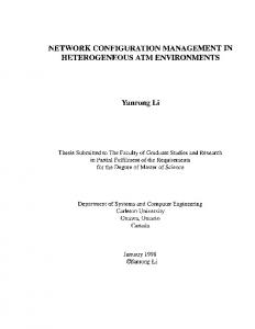
internal virtual networks and virtual machine filesystems) (Fig. 4). Optionally it can also include a description of the configuration of the virtualization back-end (e.g., the maximum number of virtual machines that the physical host can run without overloading its CPU and memory). The transformation process for VNUML-based testbeds consists of two conceptual steps. The first one merges the input TIM with the testbed model described by the testbed parameters. Basically, it associates the logical entities in the TIM with the resources in the testbed. For example, each node is associated with a corresponding virtual machine filesystem and the link with a virtual bridge. Additional information related with the deployment could be also added to nodes (like the memory amount used by each virtual machine). The second step is to adapt the TSM to the specific format that the deployment tool (i.e., VNUML) uses. In this case, this format consists in a XML file with a specific semantic. Regarding the TSM (or VNUML specification), it is made of three main sections: global, virtual networks and virtual machines (a complete reference can be found at [29]). The global section allows defining general parameters and default values that affect the whole scenario, like the way virtual machines are accessed (through x-terminals or SSH –Secure Shell– connections) or the default kernel or used filesystems. The virtual networks section defines the networks that interconnect virtual machines among them or with the host network interfaces by means of the tag. Virtual networks are implemented by means of virtual software bridges running on the host machine. The virtual machines section describes (by means of the
tag) each virtual machine included in the scenario. The language allows describing their main characteristics in terms of: the kernel and the filesystem they run ( and tags), the network interfaces they have ( tag) and the addresses associated with them, either IPv4 or IPv6 ( and tags), as well as the IP routes ( tag). The OSPF-TE entities are not included in the TSM, because VNUML does not (yet) support the deployment of these processes. This illustrates an interesting capability: the transformation step can “prune” elements in the TIM not supported by a particular testbed, providing a “clean” TSM to the deployment tools. Note that this does not mean that OSPF-TE is not supported in the virtual-based testbed at all, only that configuring and launching these entities in the virtual machines has to be done manually. Once the TSM has been generated, the user invokes VNUML (which runs in the physical host) to process it and start the virtual network scenario. During this step, all the virtual machines and virtual networks that made up the scenario are started and interconnected inside the host machine. Then, the user interacts with the scenario to achieve his/her experimentation or educational goals. Interaction with virtual machines can be achieved accessing them through their consoles (VNUML also allows executing programmed command sequences on them automatically). Eventually, user runs VNUML to dismantle the scenario and releases all the host resources used. In this way, VNUML relieves the users of all the complex UML details that the creation of virtual network scenarios requires.
Testbed parameters
Sample Model (Fig.3)
TIM
Merge
IfaceNet1
Node1
VmFilesystem1
IfaceNet2
Node2
VmFilesystem2
Link
VirtualBridge1
VNUML Model (XML)
Adapt
TIM to TSM transformation
VNUML Tool
TSM
[…] […]
Node1
physical host
Fig. 4.
EDIV Tool
Node2
Node1
Node2
cluster
VNUML-based (or EDIV-based) virtual testbed use case
VNUML considers deployment in just one physical host. However, this limitation has been recently overcome with the development of the EDIV tool [35], which is able to distribute a VNUML-based virtual scenario over several host machines (i.e. a cluster). It is worth mentioning that both VNUML or EDIV are compatible at TSM level, so they use the same TIMto-TSM transformation, as illustrated in Fig. 4. In the case of using EDIV, however, the testbed parameters description would use a Cluster object instead of PhysicalHost. Besides, proposals to extend VNUML to support other virtualization technologies (mainly Xen [36]) and formats (such as OVF [37]) are being studied. B. ADRENALINE Testbed The ADRENALINE (All-optical Dynamic REliable Network hAndLINg IP/Ethernet Gigabit traffic with QoS) testbed [3] is a GMPLS-based Intelligent Optical Network developed at CTTC laboratories. Apart from an all-optical transport plane that lies out of the scope of this paper, the testbed implements a distributed GMPLS-based control plane [38]. The control plane is responsible for handling dynamically and in real-time optical node’s resources in order to manage automatic provisioning and survivability of lightpaths (RSVP-TE signalling protocol for wavelength reservation, and OSPF-TE routing protocol for topology and optical resources dissemination), allowing traffic engineering algorithms with QoS. The control plane is composed of Optical Connection Controller (OCC) nodes, each one made on a Linux-based router with an Intel Xeon 3.0 GHz 1GB RAM running the Debian operating system. There are currently 42 OCCs in total, interconnected through a backplane of VLAN-capable switches which allow implementing any desired topology for the control plane. This ability makes ADRENALINE a flexible
testbed which enables the deployment of different network topologies and configurations (i.e., experimentation scenarios). ADNETCONF (Adrenaline NETwork CONFigurator) [39] is the deployment tool in charge of scenario model management in ADRENALINE. Since its development in early 2006, ADNETCONF has been extensively used in ADRENALINE to overcome the previously existing problems of manual reconfigurations, thus highly increasing the experimentation productivity of the testbed. It has helped to develop scenarios used in distributed shared path protection algorithms research [40][41]. In this case, the testbed description for the TIM to TSM transformation consists of the PhysicalOccs along with the Switches that interconnect then (Fig. 5), maybe including a description of its capabilities (e.g., maximum number of VLAN supported in each switch) and other deployment scenario relevant information (e.g., which binary implements each control plane process in the OCCs). The transformation steps are the same than in the VNUML use case in the previous section. The merge step associates each node with the PhysicalOcc assigned to it. Additionally, it associates the node interfaces to physical interfaces on the OCCs and the link with the VLAN that will implement it in the switches (e.g., VLAN ID 601). The adaptation step produces the TSM in the specific format for ADNETCONF. The TSM is composed of a set of XML files that correspond to the formal representation of the scenario that is understandable by the ADNETCONF processing engine. Up to six different XML files are produced; one describing the logical network topology (mandatory), the other five describing the configuration of the different processes of the control plane (LRM, OSPF-TE, RSVP-TE, SNMP, OLRM), only needed when the particular process has been included in the scenario
Testbed parameters
Sample Model (Fig. 3)
TIM
Merge
Adapt
TIM to TSM transformation
[…] 601 10.0.5.1 10.0.5.2
ADNETCONF VV Model (XML)
ADNETCONF Tool
TSM
10.0.50.0/24 10.0.50.0/24
OSPF Ent1
OSPF Ent2
Node1
Node2
ADRENALINE Testbed
Fig. 5.
ADRENALINE testbed use case
(in our example, only the OSPF-TE is used). This modularization obeys software implementation reasons, allowing a better implementation of the engine, which is composed of several modules each one specialized in validating and processing one XML file. The ADNETCONF processing engine runs in a control node that is physically interconnected to the testbed elements. The processing of the TSM produces interaction with the OCCs and switches through a dedicated control connection (considered fixed and out of the scenario deployment management). There are two possible interactions: issuing commands (always) and installing configuration files (only in some cases). Specifically, SSH and Telnet are used to provide control connections for OCCs and switches respectively. The commands issued in the most complete deployment case (i.e., the most complete network scenarios) include VLANs set up for OCCs and switches and processes start-up for OCCs (LRM, OSPFTE, RSVP-TE, SNMP and OLRM; two configurations files are generated and installed for OSPF-TE in each OCC before starting the process; one configuration file for LRM, SNMP and RSVP-TE; and none for OLRM). V. C ONCLUSIONS AND F UTURE W ORK The present paper has proposed several contributions to the configuration management field in the context of flexible IPbased networking testbeds. First, it presents the model-driven methodology that solves the problems of manual operation and inter-testbed integration and provides a base framework for the other contributions. Secondly, it provides the testbedindependent model (TIM) as a CIM Profile (consisting of a Core of basic networking plus Extensions modelling specific functionalities), after considering several modelling approaches (XML, ontologies and MDA) from the point of
view of its transformability. Third, two cases of fully functional model-based deployment tools (VNUML and ADNETCONF) which extensive use (see the references in Sect. IV-A and IV-B) in two rather different fields (virtual testbeds and optical networking) assess the usefulness of the proposed approach. It is worth mentioning that, although we have provided use cases for two testbeds, the TIM and associated model transformation methodology is applicable to any other testbed as long as they include model-oriented tools to process TSM (or they can be easily developed), given the completeness (achieved thanks to the TIM Extensions) and transformability requirements explained in Sect. III-B. Using a CIM profile to define the TIM provides a great flexibility, because of the transformation process can be defined at both conceptual (MDA, considering the CIM UML profile) and concrete (XSLT/XQuery, considering the CIMXML representation) abstraction levels. Regarding the adaptation step (see Fig. 4 and Fig. 5), it can be quite straightforward in some cases (e.g., for VNUML and ADNETCONF TSMs it would consists in XSLT or XQuery transformations) but complex in others (e.g., pre-existing testbeds like Emulab, which deployment tools use a ns2-based TSM [1]). Note that the efficient configuration management of experimentation scenarios will become a very important issue in the recent global initiatives that are currenlty arising, such as GENI (in the United States) or FEDERICA (in Europe). These large and highly distributed multi-user experimentation facilities will need management mechanisms that maximize the usage of the infrastructure. In this context, the scenariobased model-driven approach described in this paper is a sound candidate to fill the configuration management gap. Regarding future working lines, the architecture and methodology can be improved. The current version of the
testbed-independent model (Sect. III) considers static scenarios. However, it could be interesting to model dynamic behaviour (i.e., links that go down and up following a userdefined schedule) in order to perform some kind of experiments. This also involves changes in the deployment tools to implement event schedulers (as a matter of fact, VNUML includes some functionality in this direction with the and tags). Additionally, scenarios are monolithically deployed (i.e., the scenario is deployed or undeployed as a whole) while it could be interesting to deploy only parts of the scenario, especially in the case of very big models. This involves improvements in the deployment tools, to work in “atomic” rather than “monolithical” way. Other working lines that would be interesting to explore are the formalization of the testbeds parameteres (trying to define a Common Testbed Model suitable for the most of the networking testbed extisting today), and configuration validation (ensuring that a given TIM or TSM is correct and complete before starting transforming or deploying). Finally, improvements in the deployment tools themselves are also being studied (e.g. the decoupling of the virtualization technology for VNUML; or the configuration of new networking processes, such as PCE [42] for ADNETCONF). R EFERENCES [1] B. White et al., “An integrated experimental environment for distributed systems and networks”, OSDI 2002, pp. 255–270, December 2002. [2] L. Peterson et al., “A blueprint for introducing disruptive technology into Internet”, HotNets-I, Princenton, NJ USA, October 2002. [3] R. Mu˜noz et al., “The ADRENALINE test-bed: integrating GMPLS, XML and SNMP in transparent DWDM networks”, IEEE Communications Magazine, vol. 43(8), pp. s40–s48, August 2005. [4] L. Peterson, “GENI Facility Design”, GENI Design Document, GDD07-44, GENI, March 2007. [5] Federated E-infrastructure Dedicated to European Researchers Innovating in Computing network Architectures. [Online]. Available: http://www.fp7-federica.eu/ [6] International Telecommunication Union, “TMN Management Functions”, ITU-T Recommendation M.3400, ITU-T, February 2000. [7] F. Gal´an, J. E. L´opez de Vergara, D. Fern´andez, and R. Mu˜noz, “A Model-driven Configuration Management Methodology for Testbed Infrastructure”, IEEE/IFIP Network Operations and Management Symposium (NOMS), pp. 747–750, Salvador da Bahia (Brazil), April 2008. [8] R. H¨ulsemann et al., “A set of typical network scenarios for network modeling”, 5th ITG-Workshop on Photonic Networks, 2004. [9] The Network Simulator ns2. [Online]. Available: http://www.isi.edu/nsnam/ns/ [10] European Telecommunications Standards Institute, “TTCN-3: Core Language”, ES 201 873-1, version 3.4.1, ETSI, September 2008. [11] Object Management Group, “MDA guide version 1.0.1”, OMG Document omg/03-06-01, June 2003. [12] C. Atkinson, T. K¨uhne, “Model-Driven Development: A Metamodeling Foundation”, IEEE Software Magazine, vol. 20(5), pp. 36–41, September/October 2003. [13] T. Bray et al., “XML 1.1. (second edition)”, WC3 Recommendation, August 2006. [14] J. Clark, ed., “XSL Transformations (XSLT), Version 1.0”, W3C Recommendation, November 1999 [15] S. Boag et al., “XQuery 1.0: An XML Query Language”, W3C Recommendation, January 2007 [16] R. Studer, R. Benjamins, and D. Fensel, “Knowledge engineering: principles and methods”, IEEE Transactions on Data and Knowledge Engineering, vol. 25(1-2), pp. 161–197, March 1998. [17] J. E. L´opez de Vergara, V. A. Villagr´a, J. I. Asensio, and J. Berrocal, “Ontologies: giving semantics to network management models”, IEEE Network, vol. 17(3), pp. 15–21, May/June 2003.
[18] A. Guerrero, V. A. Villagr´a, J. E. L´opez de Vergara, A. S´anchez-Maci´an, and J. Berrocal, “Ontology-based policy refinement using SWRL rules for management information definitions in OWL”, DSOM 2006, Dublin (Ireland), October 2006 (Springer, LNCS, vol. 4269, pp. 227–232). [19] A. S´anchez-Maci´an, J. E. L´opez de Vergara, E. Pastor, and L. Bellido, “A system for monitoring, assessing and certifying quality of service in telematics services”, Knowledge-based systems, vol. 21(2), March 2008. [20] Object Management Group, “MOF QVT Final Adopted Specification”, OMG Document ptc/05-11-01, November 2005. [21] Distrituted Management Task Force, “CIM Infrastructure”, version 2.5.0a, DMTF Document, DSP0004, May 2008. [22] Distrituted Management Task Force, “Representation of CIM in XML”, version 2.3.0c, DMTF Document, DSP0201, September 2007. [23] Distrituted Management Task Force, “UML profile for CIM”, version 1.0, DMTF Document, DSP0219, June 2007. [24] E. Lavinal, T. Desprats, and Y. Raynaud, “A conceptual framework for building CIM-based ontologies”, 8th IFIP/IEEE Symposium on Integrated Network Management (IM), pp. 135–138, Colorado Springs, CO USA, March 2003. [25] J. E. L´opez de Vergara, V. A. Villagr´a, and J. Berrocal, “Applying the web ontology language to management information definitions”, IEEE Communications Magazine, vol. 42(7), pp. 68–74, July 2004. [26] S. Quirolgico et al., “Toward a formal common information model ontology”, WISE 2004, Brisbane, Australia, November 2004 (Springer LNCS, vol. 3307, pp. 11–21). [27] Distrituted Management Task Force, “IP Interface Profile”, version 1.0,0a, DMTF Document, DSP1036, July 2007. [28] Object Management Group, “MOF 2.0/XMI Mapping, Version 2.1.1”, OMG Document ptc/07-12-01, December 2007. [29] F. Gal´an, D. Fern´andez, W. Fuertes, M. G´omez, J. E. L´opez de Vergara, “Scenario-based Virtual Network Infrastructure Management in Research and Educational Testbeds with VNUML: Application Cases and Current Challenges”, Annals of Telecommunications, Special issue on Virtualization, 2009, in press. [30] J. Dike, “User Mode Linux”, Prentice Hall, 2006. [31] D. Fern´andez, F. Gal´an, and T. de Miguel, “Study and emulation of IPv6 Internet exchange (IX) based addressing models”, IEEE Communications Magazine, vol. 42(1), pp. 105–112, January 2004. [32] M. G´omez, F. Gal´an, and E. Torres, “A 3GPP System Architecture Evolution Virtualized Experimentation Infrastructure for Mobility Prototyping (Invited Paper)”, 4th International Conference on Testbeds and Research Infrastructures for the Development of Networks & Communities (TridentCom), Innsbruck (Austria), March 2008. [33] F. Gal´an, and D. Fern´andez, “Use of VNUML in Virtual Honeynets Deployment”, IX RECSI, Barcelona (Spain), September 2006. [34] F. Gal´an, D. Fern´andez, J. R´uiz, O. Walid, and T. de Miguel. “A Virtualization Tool in Computer Network Laboratories”, ITHET’04, Istanbul (Turkey), May 2004. [35] F. Gal´an, D. Fern´andez, M. Ferrer, and F. J. Mart´ın, “Scenario-based Distributed Virtualization Management Architecture for Multi-host Environments”, Systems and Virtualization Management 2008, Munich, Germany, October 2008 (Springer, CCIS, vol. 18, pp. 49–60). [36] P. Barham et al., “Xen and the art of virtualization”, 19th ACM Symposium on Operating Systems Principles, pp. 164–177, Bolton Landing, NY USA, 2003. [37] Distrituted Management Task Force, “Open Virtualization Format”, version 1.0.0d, DMTF Document, DSP0243, September 2008. [38] E. Mannie Ed., “Generalize Multi-Protocol Label Switching (GMPLS) Architecture”, IETF RFC 3945, October 2004. [39] F. Gal´an, and R. Mu˜noz, “An automatic model-based reconfiguration and monitoring mechanism for flexible GMPLS-based optical networking testbeds”, ONDM 2007, Athens (Greece), May 2007 (Springer, LNCS, vol. 4534, pp. 239–248). [40] R. Casellas, R. Mart´ınez, and R. Mu˜noz, “Experimental wavelength allocation policies for shared path protection in GMPLS optical networks with WCC”, IEEE Int. Conference on Communications (ICC) Workshop on Traffic Engineering in Next Generation IP Networks, June 2007. [41] R. Mart´ınez, R. Mu˜noz, R. Casellas, J. Comellas, and G. Junyent, “Experimental shared path protection algorithms in distributed all-optical GMPLS-based networks”, Proc. 6th International Workshop on the Design of Reliable Communication Networks (DRCN), La Rochelle (France), October 2007. [42] A. Farrel, J. P. Vasseur, J. Ash, “A Path Computation Element (PCE)Based Architecture”, IETF RFC 4655, August 2006.