analyst, using a library of standard models and alternative sequences of use case ... A use case map (UCM) integrates use cases to provide a whole-system ...
1
Scenario Networks for Software Specification and Scenario Management TR-2001-15 Thomas A. Alspaugh, Student Member, IEEE, and Annie I. Ant´on, Member, IEEE Abstract— Scenarios are widely used to specify the desired behavior of a system, but managing the large collection of scenarios that frequently result and making a scenario-based specification complete are challenging tasks. Scenario networks address these challenges while retaining the many advantages of scenarios during software specification activities. A scenario network is a collection of scenarios that has been integrated into a single entity by the specification of the sequential and concurrent relationships among its component scenarios. The addition of these relationships specifies the larger-scale behavior that is typically missing from a collection of scenarios, and ties scenarios together in a way that either indicates no gaps in the description are present, or makes gaps obvious. Scenario networks provide procedural guidance for scenario creation and support for scenario management. Gaps in the structure of a scenario network correspond to missing or incomplete scenarios, and the closing of these gaps result in the completion of the scenario collection. A scenario network organizes the collection of its scenarios, and its structure indicates several kinds of scenario relationships, including equivalence relations dividing them into equivalence classes. These relationships address some of the challenges associated with scenario management. Keywords— Scenario networks, requirements engineering, scenario analysis, scenario management, software specification.
I. Introduction
T
HE use of scenarios in software development has become increasingly common [1]. Scenarios are useful for describing required behavior that a system will have; expressing what part of a system is visible from a particular viewpoint; and specifying test case the system should pass. A scenario is a sequence of events, each consisting of an actor (human or otherwise) who performs the event and the action that is performed [2]. Scenarios are typically expressed in prose and thus are accessible to any reader. Since they are often expressed in the language and terms of the system stakeholders, they can be understood by the stakeholders as well as by analysts and developers. Each scenario narrates a sequence of events, and this focus helps the scenario author in choosing what facts the scenario should cover, and the scenario reader in relating the facts the scenario presents. While scenarios have proven beneficial [1], [3], [4], [5], [6], [7], their use also involves certain challenges [1], [2]. A scenario is inherently partial; each scenario offers a single view of a single part of a system’s behavior. Even a large collecT. A. Alspaugh (corresponding author) and A. I. Ant´ on are at the Department of Computer Science, North Carolina State University, 1010 Main Campus Drive (EGRC 408), Raleigh, NC 27695-7534 U.S.A. Email: {taalspau,aianton}@eos.ncsu.edu.
tion of scenarios may not provide a complete description of a system, and it is difficult to determine to what extent the collection is complete. Additionally, the relationships and dependencies between scenarios in a collection are not obvious. Finally, the scenarios in a collection are unlikely to be consistent with each other, especially after the intended behavior of the system has evolved during development. These challenges, inherent in scenario-driven requirements engineering, have been a central motivation for our work. This work has two objectives: (1) to ensure requirements coverage via the specification of a complete and consistent set of scenarios, and (2) to develop strategies to support scenario evolution and management. The kind of specification information that is typically missing from a collection of scenarios consists of information that is on a larger scale than a single scenario, such as temporal, causal, or dependency relationships between scenarios. The temporal relationships between scenarios are an important part of the intended behavior of the system. Causal relationships between scenarios express that the occurrence of one scenario can cause or prevent the occurrence of another scenario, whether immediately or at some later time. Dependency relationships between scenarios express that for a particular scenario, the events chosen for it, the scope of its effects, the form in which it is expressed, or other features of it depend on some aspect of another scenario. A number of other relationships between scenarios can be significant, such as interchangeability between scenarios or substitutability of one scenario for another. These relationships are not typically expressed in a collection of scenarios, or supported by current approaches to scenario-driven requirements engineering. In this paper we discuss our approach for expressing this missing information using scenario networks. A scenario network is a collection of scenarios whose sequential and concurrent relationships have been made explicit. It can be used to provide a complete specification of a system’s important behavior, including not only the behavior expressed in individual scenarios but also behavior that spans more than one scenario. The unification and integration of its constituent scenarios contributes to improving the quality of those scenarios; aids in determining whether the collection of scenarios is complete; and guides the process of completing them. Throughout the paper we use the Enhanced Messaging System (EMS) as an example [5]. The EMS is a comprehensive telephone voice messaging system which supports a
2
wide range of functionality, including: access and authentication; subscriber interactions with the EMS (e.g. notifications and message processing); caller interactions with the EMS (e.g. recording of incoming messages and the marking of certain messages as urgent); as well as recording, playing, and archiving of subscriber outgoing messages. The remainder of this paper is organized as follows. Section 2 of this paper summarizes related work. Section 3 introduces scenario networks. Section 4 presents the relationships between scenarios that scenario networks support. Section 5 compares two approaches for constructing a scenario network. Section 6 discusses the application of scenario networks to software development. Section 7 summarizes our findings and plans for future work. II. Related work Our work on scenario networks builds upon research in a number of areas in requirements engineering. Each subsection below provides an introduction to one of these areas, summarizes the most pertinent related work, and discusses how scenario networks build upon that work. A. Scenario management We use the term scenario management to refer to the management and administration of a collection of scenarios. Scenario management addresses issues that arise as the number of scenarios for a system increases, such as organizing, listing, and classifying the scenarios for the system; tracing dependencies among scenarios, and between scenarios and other artifacts; determining and maintaining relationships among scenarios; finding the scenario that defines a particular behavior of the system; detecting and eliminating duplicate or near-duplicate scenarios; managing inconsistencies among scenarios; and determining whether a group of scenarios is complete. It is needed for any system with more scenarios than one person can keep track of in his or her head. These issues have received little attention. In their survey of the use of scenarios in industry, Weidenhaupt et al. note that the creation, documentation, and validation of scenarios is a substantial effort in itself [1]. Traceability, maintenance of consistency with other artifacts, and scenario evolution and management are significant problems that have not been adequately addressed by research [1]. Jarke et al. also note that little research addresses the problems that arise in managing a large set of scenarios [8]. A special issue of the IEEE Transactions on Software Engineering [9] is devoted to scenario management, and a related issue of the Requirements Engineering Journal [10] is devoted to interdisciplinary uses of scenarios, but the articles in these two issues address the use of scenarios for various purposes in various situations, rather than the management of scenarios themselves (with the exception of Jarke et al. [8], which contains a section on “scenario management in the large”). More recently, Alspaugh et al. have proposed an approach to scenario management based on glossaries, episodes (scenario fragments that appear in several scenarios), and measures of similarity between scenar-
ios. The approach uses a purely syntactic view of scenarios to support analysts as they work to make their scenarios consistent; trace and maintain dependencies among scenarios; look for scenarios that address a particular behavior; and determine completeness of a group of scenarios [2]. Scenario networks provide an organizing structure for a system’s scenarios, and the scenario relationships that a scenario network uncovers provide ways to classify the scenarios. B. Scenario process guidance Scenario process guidance refers to methods and heuristics that guide the process of creating and refining scenarios. Such process guidance helps analysts identify areas of system behavior that no existing scenario addresses; locate scenarios that conflict with each other; and identify scenarios that either do not sufficiently specify important behavior, or that over-constrain by specifying unnecessary or irrelevant details. Weidenhaupt et al. observed that most developers viewed the creation of scenarios as a craft rather than an engineering activity, and that effective theories and heuristics for guiding the creation and refinement of scenarios are needed [1]. Several researchers have proposed heuristics and theories to support them. Potts et al. discuss the refinement of scenarios through the technique of scenario walkthroughs in their Inquiry Cycle [3]. Sutcliffe, Maiden, et al. attack the problem of missing scenarios with a method supported by their CREWS-SAVRE tool. In this method, new scenarios are automatically generated for consideration by an analyst, using a library of standard models and alternative sequences of use case events [4], [11]. Rolland and Ben Achour present a process that begins with a context and initial scenario for a use case, and then guides the capture and completion of new scenarios and their integration into the use case [12]. The process employs guidelines for effective expression of use cases in prose, and rules that ask for more information or generate a new use case element from what is already known. The guidelines and rules are based on linguistic patterns and structures [12]. The work on viewpoints discussed below provides process guidance for improving consistency among scenarios. Process guidance is an important benefit of the use of scenario networks. A scenario network aids in identifying missing scenarios and behaviors by forcing analysts to consider how the scenarios can occur in sequences or concurrently. The consistency this enforces between scenarios is different than that provided by viewpoints. C. Viewpoints A viewpoint is a partial specification of a system from a particular perspective [13], [14]. This is usually the perspective of a single actor who interacts with the system. Viewpoints are used as a means of expressing the separate perspectives of the various actors of a system, and provide a basis for identifying and eventually reconciling inconsistencies between these perspectives.
3
Finkelstein, Nuseibeh, Easterbrook, and other researchers discuss viewpoints in requirements engineering and a formalization of them termed ViewPoints [13], [14]. For a complex system, ViewPoints provide a framework for separating the concerns of the various viewpoints. The specifications from the various viewpoints may be expressed using different specification languages and methods supported by different tools. Each viewpoint is defined in terms of the editing and consistency checking actions appropriate to it, and these actions and the inconsistencies associated with the viewpoint provide process guidance for eliciting and elaborating the specification [14]. If the specification is expressed in terms of a state transition system, then each viewpoint may have its own subset of states and of transitions between them. A particular system state or transition between states may be visible from one viewpoint but not from another. Reconciling the inconsistencies between the specifications from each of the viewpoints produces an integrated specification consisting of all the system’s states and transitions [13]. Scenario networks are similar to viewpoints in that they produce a unified system specification out of a number of smaller specifications. Viewpoints are most effective where these smaller specifications overlap at least to some extent, and viewpoints integrate the specifications by unifying common elements shared among specifications. The overlaps between specifications are the locus where viewpoint integration takes place. In contrast, the component scenarios of a scenario network are required to not overlap; in a scenario network, overlaps between scenarios are eliminated so that each part of the system’s behavior is expressed in exactly one place. A scenario network integrates its specifications by connecting the exit point of each scenario with the entry points of all scenarios that can follow it. The connections between scenario exits and entries are the locus where integration of a scenario network takes place. D. Scenario integration We use the term scenario integration to refer to any process that unifies a group of scenarios into a single larger entity. Scenario integration is not frequently practiced; scenarios are generally used as individual partial specifications. This practice exacerbates the problems of missing scenarios (and completeness in general), inconsistency between scenarios, and lack of conceptual unity of the system being described. Dano et al. integrate scenarios based on the temporal relationships between them, and construct corresponding Petri nets, as part of their work on formalizing domainexpert use cases and producing object type state diagrams from them [15]. A use case map (UCM) integrates use cases to provide a whole-system specification [16], [17]. The use cases are expressed as causal sequences of responsibilities and denoted graphically as a graph with responsibilities attached. Concurrency is explicitly represented in a UCM. The original emphasis was on binding responsibilities to system components and elicitation of requirements and de-
sign information. Feature interaction is examined visually by inspection of the UCM notation. More recently, UCMs have been used to express whole-system behavior, and formalized by (manual) translation into the specification language LOTOS [18]. Sendall’s operation schemas are system operations, corresponding to Jacobson’s transactions that make up use cases, augmented by pre- and postconditions (and other information) [19]. The conditions express when each operation can occur and the effect of each operation. The operation schemas for a system are thus implicitly integrated into a single specification. The use cases that contain the system operations become emergent phenomena of the operation schemas for the system. A use case itself can be considered to integrate some of the scenarios of a system, since it can describe both a principal sequence of actions and also possible variants for alternate orderings, exceptional cases, or error handling [20]. Only scenarios that are variants on each other are contained in a single use case, however. Viewpoints provide a means of integrating overlapping scenarios, as discussed above [13], [14]. Scenario integration is one of the primary results and benefits of creating a scenario network. Scenario networks are similar to UCMs in that both of them provide a graphic notation that indicates how scenarios (use cases) can occur temporally. Scenario networks add techniques for assessing and improving completeness of the collection of scenarios and consistency among the scenarios. E. Preconditions and postconditions for scenarios Pre- and postconditions for scenarios express what each scenario requires and achieves. A scenario’s precondition expresses what the scenario expects to be true when it begins, and a scenario’s postcondition expresses what the scenario guarantees to be true when it concludes (if its precondition was met). Pre- and postconditions are widely used in many contexts. A number of researchers have attached pre- and postconditions (or, equivalently, initial and final states) specifically to scenarios. Rolland and Ben Achour use initial states of agents and final states of episodes to guide the writing of use cases involving these agents and episodes [12]. Rolland et al. attach initial and final states to scenarios in their L’Ecritoire tool in support of a heuristic to guide the search for additional goals [21]. Scenario networks use pre- and postconditions for scenarios to restrict the sequences of scenarios expressed by a scenario network. F. Scenario relationships A scenario relationship expresses equivalence, ordering, causality, inheritance, or some other connection between two scenarios. Examples of scenario relationships between any scenarios SA and SB are given in Table I. Jacobson et al. discussed the “uses” and “extends” relationships in their original work on use cases [22]. Simons and others note that the Jacobson and the Unified Modeling Language (UML) definitions and redefinitions of “uses”
4
SA SA SA SA SA SA
uses SB extends SB is equivalent to SB is a subset of SB overlaps with SB depends on SB
TABLE I Commonly Used Scenario Relationships
and “extends” have been problematic and are still not entirely satisfactory; they induce arbitrary goto-like jumps in the flow of control, “extends” is used in the literature and in practice for purposes for which it is not adequate, and neither relationship is sufficient to address long-range dependencies between use cases [23]. Breitman and Leite define and use relationships between scenarios (overlap, equivalence, and subset) to classify and guide the evolution of scenarios [24]. Alspaugh et al. discuss the importance of dependency relationships between scenarios and their preservation as the scenarios evolve [2]. Scenario networks provide a basis for several new scenario relationships which we introduce in Section IV. These relationships are used in the construction and refinement of the scenario network and its constituent scenarios. G. Concurrency between scenarios Concurrency in requirements specification has been addressed by, for example, the CoRE method [25] the modeling approach of Coleman et al. [26], and the Specification and Description Language (SDL) and Message Sequence Charts (MSC) [27], [28]. Surprisingly little research has focused on concurrency between scenarios, however. A scenario is a sequence of actions and this sequence of actions tends to obscure the fact that in general a scenario occurs concurrently with other activity in the system. Desharnais et al. use a state-based formalization of scenarios to explicitly represent concurrency between scenarios [29]. The graphic notation of UCMs expresses the concurrency that is desired between use cases, and has been used to detect feature interactions [16]. There is a large body of established work on concurrency and concurrent systems [30], [31], [32], but it been little applied to concurrency between scenarios. Scenario networks begin to address concurrency between scenarios and this continues to be an area of focus for future work. H. Specification formalisms for modelling A specification formalism is a basis for constructing a formal model whose behavior mimics important aspects of the system it specifies, but which is abstract, compact, and amenable to analysis. Whereas requirements describe a system by presenting its properties, a model describes a system by behaving like or simulating it. There are a wide variety of specification formalisms, each with its own
strengths and weaknesses and areas of greatest applicability. We discuss the formalisms that are most relevant to scenario networks: Petri nets, high-level message sequence charts, and extended finite state machines. A Petri net is a directed graph with two kinds of nodes, places and transitions, and with arcs that run either from places to transitions or from transitions to places [33]. If an arc runs from a node c to another node d (whether a place or transition) then c is said to be an input to d, and d an output from c. The state of the Petri net is indicated by the presence of tokens in one or more places, and a token moves from one place to another when a transition between them fires. A transition can fire when all of its input places are occupied by tokens, and when a transition fires all of its output places receive tokens. Thus, concurrency is inherent in Petri nets and they are particularly useful in modelling concurrent systems. Petri nets are supported by almost four decades of research and a number of software tools [33]. The structure of Petri nets does not map to the structure of the systems they describe or the problems they solve, however, so it can be difficult to trace a feature of a Petri net to a feature of a description of the system in another form. High-Level Message Sequence Charts (HMSCs) are a formalism for describing systems in terms of Message Sequence Charts (MSCs) [28]. A Message Sequence Chart is a graphical representation of sequences of messages transmitted between instances (systems, components, processes, etc.) [28], [34]. A basic MSC is roughly comparable in function to a scenario, with messages or actions of an MSC corresponding to events of a scenario. MSCs may be far more complex than scenarios, however, with timers and quantified times, conditions for restricting message sequences, alternation, iteration, concurrency, references to other MSCs, and various other features for specifying partially or totally ordered sequences of messages. A High-level Message Sequence Chart connects individual MSCs, not using the MSC notation as its name suggests but an unrelated notation that indicates sequential composition, alternation, iteration, concurrency between two HMSCs, and recursive composition in which a node of an HMSC can itself be an HMSC [28], [35]. An extended finite state machine is a finite state machine (FSM) whose states have been augmented by variables [36]. The global state of the machine then consists of its explicit state (one or more of the nodes of its diagram) plus its extended state (the values of the variables). The variables may be external to the FSM or local to it, in which case their scope may be all the states and transitions or some subset of them. The values of the variables can be changed by the explicit state, by transitions between explicit states, or possibly from outside the extended FSM; the values of the variables may be used as guards for each transition. Extended FSMs are widely used to describe many sorts of systems, and occur in several variants, including Statecharts [37], [38] and state diagrams in the Specification and Description Language (SDL) [27], [39]. Statecharts extend the basic idea of extended FSMs with several sorts of com-
5
position, including concurrency and clustering of states to ameliorate state explosion. They are widely used (for example in UML) and software tools such as StateMate are available to support them. SDL was developed especially for telecommunications and embedded systems (as were MSCs and HMSCs), and is most commonly employed in those domains. A scenario network is an extended finite state machine that has been adapted to express temporal and causal relationships between scenarios. Its nodes are scenarios, and its transitions represent possible paths from one scenario to another. Paths that initiate a new instance of concurrency are marked to distinguish them. Unlike the transitions of an FSM, the transitions of a scenario network are not labelled with inputs, because the event that triggers a transition is part of the scenario the transition leads to. Each scenario is guarded by a precondition expressed in the primitive terms of the network (corresponding to the extended state of an extended FSM), and has a postcondition expressing the scenario’s effect on the primitive terms. Scenario networks express sequences of actions, as do Statecharts, MSCs, and HMSCs, and like Statecharts and HMSCs the graphic notation for scenario networks is based on that of FSMs and transition systems in general. We limit scenario networks to a simpler structure than that of Statecharts, MSCs, and HMSCs in order to concentrate on relationships between scenarios, and to focus on the requirements engineering and process challenges that are made clear and can be mitigated even with this simple structure. Scenario networks differ from Petri nets in a number of ways, notably in that scenario networks do not possess separate transition and place nodes, and the form of a scenario network is directly traceable to significant aspects of the behavior of the system it describes. III. Scenario networks This section defines specific terminology and introduces scenario networks. A. Terminology We define the following key terms. A scenario is a sequence of events, plus possibly some associated attributes such as pre- and postconditions [2]. Each event consists of an action and an actor that performs it. An actor may be a specific person, component, or system, or may be an unbound role or parameter that can be filled by any of several specific actors. A scenario network is comprised of a group of scenarios and the interconnections between them that indicate the allowed scenario sequences and concurrency. The interconnections are restricted by the pre- and postconditions of each scenario. At least one of the scenarios is distinguished as initial, and at least one other as terminal. A multipath is a possibly ramified path along the connections between the scenarios of a scenario network. In its simplest form without concurrency, a multipath is simply a sequence of scenarios. Where concurrency is possible, a multipath can ramify into several concurrent sequences.
An initial scenario of a network is one that can begin a multipath in the network, and can appear nowhere else. A terminal scenario of a network is one that can end a branch of a multipath in the network, and can appear nowhere else. The precondition of a scenario is a logical expression that must be true in order for the scenario to begin. The precondition of scenario SA is denoted Pre(SA ). The postcondition of a scenario is a logical expression that is guaranteed to be true after the scenario concludes. The postcondition of scenario SA is denoted Post(SA ). The primitive terms of a network are a set of variables of Boolean, integer, or other types, in which the conditions of scenarios in the network are expressed. The follow set of a scenario is the set of scenarios in its network that can follow it in a sequence. The follow set of scenario SA is denoted Follow(SA ). The precede set of a scenario is the set of scenarios in its network that can precede it in a sequence; that is, the set of scenarios whose follow sets contain it. The precede set of scenario SA is denoted Precede(SA ). The ramification set of a scenario is the set of scenarios in its network that can begin a new concurrent sequence after it. The ramification set of scenario SA is denoted Ramify(SA ). B. Motivation and example Individual scenarios are frequently used to describe a single transaction or a single sequence of events accomplishing a particular purpose (as in Scenario S12 shown in Table II). A scenario describes part of a system’s behavior, and a group of scenarios describes the entire behavior of a system. Ideally, every system behavior is expressed by one or more scenarios in the group. For illustration, we consider scenarios for the Enhanced Messaging System, a voice mail system discussed in our earlier case study [5].
1. 2. 3.
S12 . Subscriber listens to the next message. Subscriber s dials the next message command. EMS plays s’s next message. If that message was ‘new’, its state becomes ‘old’ TABLE II EMS Scenario S12
What is not expressed by a group of scenarios is the allowed temporal relationships among all the scenarios. There is no specification of either the allowable sequences of scenarios or concurrency between sequences of scenarios. Scenario networks provide a way to express this additional information. Any allowable behavior of the system corresponds to a (possibly ramified) path through the network, beginning at an initial scenario and continuing until each branch of the path reaches a terminal scenario. A detailed example of a sequential scenario network for a simplified EMS is presented in our earlier work [5]. Here we
6
present an example from the complete EMS that demonstrates concurrency, using the scenarios listed in Table III. S0 S1 S2 S12 S13 S29 S30 S39
EMS startup. EMS shutdown. Subscriber calls EMS, authenticates him/herself. Subscriber listens to the next message. Subscriber has no more messages to listen to. Subscriber disconnects from EMS. Caller calls a subscriber and leaves a message. Caller disconnects from EMS. TABLE III EMS scenarios used in the example
In the context of the EMS, expected or desired behaviors are represented by a number of multipaths through the scenarios listed in Table III. Wherever a multipath diverges into two or more paths, it indicates concurrency between the scenario sequences on the parallel paths. Some allowed multipaths for the EMS are listed in Figure 1.
S0 S0
- S1 - S2 - S13 - S29 § - S30- S39 ¨ - S1 - S30- S39 ¨ - S1 - S2 - S13 - S29 § - S30- S39 ¨
S0
- S1 - S2 - S12 - S29 §
- S30- S39 ¨ S0
- S1 - S2 - S12 - S13 - S29 §
- S30- S39 ¨ S0
Initial scenarios Terminal scenarios Scenario S0 S1 S2 S12 S13 S29 S30 S39
Ramification set S2 , S30 ∅ ∅ ∅ ∅ ∅ ∅ ∅
- S1 - S2 - S12 - S29 § - S30- S39 §
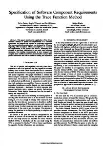
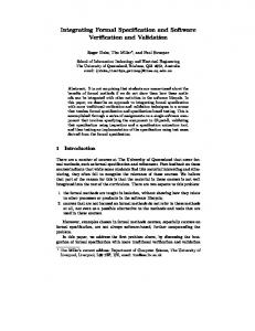
A second way to express a scenario network is by producing a diagram in which scenarios, represented by circles, are connected by arrows indicating sequence, and slashed arrows indicating where multipaths through the network may branch, as portrayed by the scenario network diagrams in Figures 2 and 3. Figure 2 shows the entire scenario network diagram for the completed EMS. In the diagram, scenarios are represented by labelled circles, and transitions between them by arrows. Each dotted circle indicates the Cartesian product of all arrows into it with all arrows out of it, and all arrows out with all arrows in; otherwise the diagram would contain a thicket of arrows. For example, at the dotted Cartesian product circle in the upper right, the arrow from S37 into the product stands for seven arrows: one from S37 to each of S31 through S35 , S38 , and S39 . For purposes of illustration in this paper, we focus our discussion on a portion of the scenario network shown in Figure 3. The scenario network in Figure 3 supports all the allowed scenario multipaths listed in Figure 1, and an infinite number of others. However, it also supports an infinite number of scenario multipaths that should not be allowed, such as
- S30- S39 ¨ S0
S0 S1 , S29 , S39 Follow set S1 ∅ S12 , S13 , S29 S12 , S13 , S29 S12 , S13 , S29 ∅ S39 ∅
TABLE IV Tabular form for example scenario network
S0 - S1 S0
network that expresses exactly the multipaths that are allowed. We express scenario networks in one of two equivalent ways: in tabular form (see Table IV), or as a diagram (see Figure 2). In each form, the scenarios in the network may be further restricted by pre- and postconditions. For the tabular form, we list the network’s scenarios, identify those that are initial or terminal, and give each scenario’s follow set and ramification set. Table IV provides this information for the example scenarios.
- S1 § S2 S12 S12 S13 S29 - S30- S39 §
- S30- S39 ¨ S0
- S1 - S2 - S12 - S12 - S29 §
Fig. 1. Some Allowed EMS multipaths
(caller left one message but subscriber listened to two)
The list of allowed multipaths continues without end, so rather than listing the multipaths we create a scenario
Such undesired multipaths are ruled out by assigning a precondition to each scenario. A scenario’s precondition is required to be true in order for the scenario to begin. Each
7
PQRS WVUT ONML HIJK S38 WVUT PQRS HIJK ONML PQRS WVUT ONML HIJK S35 S39 O 2X 2 F 22 °° ° WVUT PQRS PQRS WVUT ° S37 MM 222 ° 8 S34 MMM °° rrrrr °F _ MM& r ° x r ° °° PQRS PQRS WVUT HIJK ONML o /WVUT S33 S9 °° ° Mf MM QQQQ O ° ° MMM Q( ² 2 X ° O 22 M& ° PQRS WVUT S0 QQQ 22 WVUT PQRS PQRS WVUT ONML HIJK °° S32 S10 Mf M QQQ 22 °° QQQ M ° M » M QQQ ° M _ M M ° QQQ MM WVUT PQRS Q( ° S31  WVUT /PQRS S30 QQQ 2 r Q r Q Q QQQ rrr QQQ rrr QQQ rrr QQQ r r QQQ r r QQQ r r r QQQ r r QQQ r r r ( xr WVUT PQRS HIJK ONML ZZZZZZZZ S1 ? -WVUT PQRS WVUT PQRS $$ ?? S WVUT PQRS HIJK ONML WVUT PQRS S 28 S27 4 S 29 $$ ?? 22 O PQRS WVUT ONML HIJK (S ( K $$ PQRS S26 22 WVUT (( ¹¹ S3 ? F $$ 22 PQRS WVUT (( ¹¹ °° ?? 22 ´ S25 ° ¹ ?? ° ( ¹ 2 ° Ä? ?? 22 ( ¹¹® ° WVUT PQRS Ä ² ° Ä S2 MM ?? 2 ° Ä PQRS WVUT » ?? ° MMM S24 ÄÄ ? MMM qq8 ÄÄ Ä MMM qqq q q M qx q PQRS WVUT PQRS WVUT S5 kVVVVVV & hhh3 S23 VV+ shhhhh WVUT PQRS S6 o /
hhh3 shhhhh PQRS WVUT 8 S7 qqq qqq q q Ä? qx ÄÄ °F WVUT PQRS S8 ÄÄ ° O Ä ¹K °° ÄÄÄ ¹¹ °° ¹ ° PQRS WVUT S §°° ¹¹ ? 12 ¹® ¹ ÄÄ PQRS WVUT ² S13 ÄÄÄ WVUT PQRS S14 PQRS WVUT PQRS WVUT HIJK ONML S15 S11
PQRS o /WVUT S22 kVVVVV VVV+ PQRS WVUT Mf MM S21 MMM MMM ?_ ? & ? ?? X11 PQRS WVUT S20 ?? 11 (S ( ? 11 (( 1 11 (( PQRS WVUT S19 » (( ¶ PQRS WVUT S18 WVUT PQRS S17
Fig. 2. Diagram of EMS scenario network
 PQRS WVUT S ? 13 ? ÄÄ O ??? Ä ? ÄÄ PQRS WVUT WVUT PQRS ONML HIJK / S S ?Ä 2 ?? ? 29 Ä ? ?? ² ÄÄÄ ÄÄ Â Ä ÄÄ Ä Ä PQRS WVUT ?? Ä S 12 ?? ÄÄ _ ?? ÄÄ ?? Ä ? Ä Â PQRS WVUT PQRS HIJK ONML /WVUT S0 S1 ? Ä? ?? ?? ?? ? WVUT PQRS WVUT ONML HIJK /PQRS S30 S39
Fig. 3. Diagram for example scenario network
scenario is also assigned a postcondition which is satisfied at the end of the scenario. At any point in a multipath we can determine which scenarios can occur by comparing their preconditions with the postconditions fulfilled by scenarios already completed. The pre- and postconditions for the example scenarios are given in Table V. Precondition – tt !s.ckg ∧ acc 0 < s.rem 0 = s.rem tt acc tt Term acc S s s.ckg s.tot s.rem
Postcondition (acc = tt) ∧ ∀s ∈ S : (s.tot 0 = 0 ) acc = ff (s.ckg 0 = tt) ∧ (s.rem 0 = s.tot) s.rem 0 = s.rem − 1 tt s.ckg 0 = ff (s.tot 0 = s.tot + 1 ) ∧ (s.rem 0 = s.rem + 1 ) S39 tt Meaning True while EMS is accepting calls. The finite set of subscribers. A subscriber in S . True while s is checking message The number of messages s has. The number of unheard messages s has. S0 S1 S2 S12 S13 S29 S30
TABLE V Pre- and postconditions of example scenarios
We note that scenario networks may appear on the surface similar to finite state machines, but there are important differences between them. Notably, each scenario’s conditions refer to a state that can be arbitrarily complex, so that a scenario network is capable of much more complex transition sequences than a finite state machine. Also, a scenario network addresses concurrency in a manner different from the way a finite state machine does nondeterminism. C. Scenario networks as system simulations Scenario networks simulate a system by presenting sequences of scenarios that correspond to desired behaviors of the system. Each individual scenario describes part of the system’s behavior in the usual way; actors correspond to people, components, or systems, and may represent all or part of the system whose behavior is of interest, or actors that are part of its environment. The events of the scenario are taken to occur in the order the scenario specifies. For the purposes of the scenario network, each scenario is considered to occur atomically; the scenario network does not reflect any details of the interior of the scenario. This simplification is to allow us to separate concerns by concentrating on relationships between scenarios, and by considering each scenario only in terms of its conditions and its follow and ramification sets. A scenario network begins a multipath with an initial scenario, then continues by following each scenario’s follow and ramification sets. A scenario is allowed to begin only
8
when it is a possible next scenario and its precondition is true; if both these are the case, the scenario can be triggered by its first event. The possible next scenarios may be visualized using one or more counters, initially a single counter on an initial scenario. The possible next scenarios are all the scenarios in the follow or ramify sets of a scenario that has a counter. If a scenario in a ramify set is triggered, a new counter is given to that scenario, indicating a new concurrent thread and beginning a new branch of the multipath. If a scenario in a follow set is triggered, that scenario is given its predecessor’s counter and the existing branch of the multipath is extended. Only one of the scenarios in the predecessor’s follow set can be triggered. When a scenario is triggered, its postcondition takes effect and may change the values of the primitive terms of the scenario network; if two scenarios or more are triggered simultaneously, we consider that their postconditions are applied in some particular sequence, without defining which of the possible sequences occurs. When each counter reaches a terminal scenario, it has no further effect since terminal nodes have empty follow and ramify sets. When all a scenario network’s counters have reached terminal nodes, the multipath is complete. We note that it is possible for a scenario network to hang, for its scenarios to set its primitive terms so no possible next scenario’s precondition is satisfied. In such a situation the multipath does not terminate and the result of the scenario network is undefined. The primitive terms of a scenario network may be individual booleans or integers or values of other sets. For example, in the EMS, there are primitive terms whose values are drawn from the set of all subscribers, a finite but dynamically changing set; others whose values are strings, lists, or other containers; and other terms whose values are attributes of a particular subscriber, analogous to fields of an object or mappings from the set of subscribers onto another set of values. It is important to note that although a scenario network simulates a system, it does not itself represent the system being modelled or any other entity in the environment. Instead, it represents possible sequences of events, nothing more, and the actors of those events may be the system or components of the system, entities in the environment, people interacting with system or in the environment, or anything else that can cause an event to occur. All these actors are distinct from the scenarios that describe them, and from the scenario networks that are made up of the scenarios. The system (and all the other actors) are present only by virtue of the events in which they participate, and these events may be distributed across many scenarios. IV. Relationships between scenarios Several kinds of relationships between scenarios are evident from the scenario sequences for a scenario network. Each of these relationships can be expressed in terms of follow sets. In the definitions below, SA , SB , SC , Ssub , and Ssuper represent arbitrary scenarios. The elementary relation can be followed by (*) expresses
follow and ramification sets as a relation. SA * SB if SB is either in SA ’s follow set or ramification set. 4
SA * SB = SB ∈ Follow(SA ) ∪ Ramify(SA ) Extended by universal quantification, * produces the follow subtype relation wfol and the precede subtype relation wpre . SA wfol SB ( SA wpre SB ) if SA can follow (precede) any scenario that SB can: 4
SA wfol SB = ∀SC .(SC * SB ) =⇒ (SC * SA ) 4
SA wpre SB = ∀SC .(SC ( SB ) =⇒ (SC ( SA ) When SA is both a follow subtype and precede subtype of SB , then SA may be substituted in any place where SB appears. The combination of these two relationships produces the can be substituted for relationship wseq . 4
SA wseq SB = (SA wfol SB ) ∧ (SA wpre SB ) Each of these reflexive and transitive relations wfol , wpre , and wseq is the basis of an equivalence relation. The follow equivalence relation ≡fol is true when wfol holds in both directions. Two scenarios are follow-equivalent when they can follow all the same scenarios. 4
SA ≡fol SB = (SA wfol SB ) ∧ (SB wfol SA ) Two scenarios are precede equivalent (≡pre ) when they can precede all the same scenarios. 4
SA ≡pre SB = (SA wpre SB ) ∧ (SB wpre SA ) A third and stronger equivalence relation sequence equivalence ≡seq is true when both ≡fol and ≡pre hold. Two scenarios are sequence-equivalent when either can be substituted for the other in any scenario sequence. 4
SA ≡seq SB = (SA ≡fol SB ) ∧ (SA ≡pre SB ) wfol and wpre , wseq , ≡fol and ≡pre , and ≡seq indicate a range of possibilities of substitution of one scenario for another. Each of these substitution relationships offers the possibility of generating plausible new sequences of scenarios by substituting into sequences already deemed acceptable, and directs attention to related scenarios that may need to track each other as changes occur. One of the most interesting relationships arising in a scenario network is a substitution relationship analogous to the behavioral subtype relationship [40], in which Ssub is a behavioral subtype of Ssuper (denoted Ssub