that void space introduces unacceptable performance degrada- tion when ... called the voidâspace reduction method. ... the destination of each arriving packet.
IEICE TRANS. COMMUN., VOL.E86–B, NO.8 AUGUST 2003
1
PAPER
Special Issue on Photonic IP Network Technologies for Next Generation Broadband Access
Scheduling Algorithm with Consideration to Void Space Reduction in Photonic Packet Switch Takashi YAMAGUCHI† , Nonmember, Ken-ichi BABA†† , Masayuki MURATA††† , and Ken-ichi KITAYAMA†††† , Members
SUMMARY In this paper, we comparatively evaluate two photonic packet switch architectures with WDM-FDL buffers for synchronized variable length packets. The first one is an output buffer type switch, which stores packets in the FDL buffer attached to each output port. Another is a shared buffer type switch, which stores packets in the shared FDL buffer. The performance of a switch is greatly influenced by its architecture and the packet scheduling algorithm. We compare the performance of these two packet switches by applying different packet scheduling algorithms. Through simulation experiments, we show that each architecture has a parameter region for achieving a better performance. For the shared buffer type switch, we found that void space introduces unacceptable performance degradation when the traffic load is high. Accordingly, we propose a void space reduction method. Our simulation results show that our proposed method enables to the shared buffer type switch to outperform the output buffer type switch even under high traffic load conditions. key words: WDM, Photonic Packet Switch, FDL Buffer, Variable Length Size Packet, Packet Scheduling Algorithm
1.
Introduction
The progress of optical transmission technology in recent years has been remarkable especially in achieving a Tbps class of transmission speed. However, as the bandwidth is increasing sharply because of advances in optical transmission technology, the electronic technology for switching systems is approaching its limit. Thus, we need a photonic network which can incorporate functions such as the multiplexing, demultiplexing, switching, and routing functions in an optical domain, through which electronic control can be minimized. Then, we can expect to see a super–high speed network that exceeds the speed limit of the electronics devices. In this paper, we study packet scheduling algorithms for the photonic packet switch. In the packet switch, packet loss is caused by the contention of more than two packets destined for the same output port. In the conventional electronic switch, the output times of †
The author is with Graduate School of Engineering Science, Osaka University, Toyonaka, Osaka, 560-8531 Japan †† The author is with Cybermedia Center, Osaka University, Ibaraki, Osaka, 567-0047 Japan ††† The author is with Cybermedia Center, Osaka University, Toyonaka, Osaka, 560-0043 Japan †††† The author is with Graduate School of Engineering, Osaka University, Suita, Osaka, 565-0871 Japan
those packets are shifted by a store-and-forward technique utilizing RAM (Random Access Memory), and resolving packet contention is a simple procedure. However, in the photonic packet switch, we need to take other approaches because RAM in an optical domain is still not available. For instance, optical buffering is achieved by using optical fiber delay lines (FDL) for packet contention resolution [1]–[4]. Using FDL, packets are stored in different lengths of delay lines, through which the departing times of packets are time-shifted. Another technique used for resolving packet contention is to introduce wavelength conversion on FDL, where the wavelengths of more than two packets contending the same output port are converted to different wavelengths by using tunable wavelength converters. Although wavelength conversion requires a higher hardware cost, it results in a better performance [5], [6]. However, once the packet is injected into the FDL, it cannot be sent to the output port for the time duration corresponding to the length of FDL. Thus, we need an effective packet scheduling algorithm for WDM-based FDL (or WDM-FDL in short), and this is the main subject of this paper. In this paper, we evaluate the performance of photonic packet switches with WDM-FDL supporting variable–length packets. We assume that all arriving packets are synchronized at the predefined time slot, and packet length is given by an integer multiple of the time slot. Note that time–synchronization of asynchronously arriving packets can be realized by the technique presented in [7]. In this paper, we consider two switching architectures. The first one is an output buffer type switch, which stores packets in the WDMFDL buffer attached to each output port. The other is a shared buffer type switch, where all the packets failing to acquire the output port are sent to the single FDL buffer within the switch. As described above, the use of a packet scheduling algorithm is important for enabling the photonic packet switches to achieve a high performance. This is especially true for the shared buffer type architecture as we will show in a later section. We apply three packet scheduling algorithms proposed in [8], [9] to the above two packet switching architectures and comparatively evaluate the performance of the switches. Also, we propose a new packet scheduling algorithm applicable to the shared buffer type switch,
IEICE TRANS. COMMUN., VOL.E86–B, NO.8 AUGUST 2003
2
called the void–space reduction method. The rest of the paper is organized as follows. In Section 2, we briefly present shared buffer type and output buffer type architectures for photonic packet switches supporting variable length packets. In Section 3, we describe packet scheduling algorithms that determine the wavelength of packets inserted in the FDL buffer, and then present our new algorithm. In Section 4, we introduce the simulation model and evaluate the two architectures. Conclusions and future work are summarized in Section 5. 2.
Asynchronous packets
t
Synchronized packets
t
Photonic Packet Switch Architectures
The photonic packet switches that we consider in this paper accept variable–length packets arriving asynchronously at the input port. Arriving packets are synchronized at a time with a predefined size. A synchronization mechanism for asynchronously arriving packets is presented in [7], see also Fig. 1. The packet length is an integer multiple of the time slot size. When we utilize FDL, the time slot size affects the performance of the switch when the variable– length packets are treated. For example, in [10], it is shown that the best performance is obtained when the time slot size is set to about 30 percent of the average packet size. We will also use this value in the simulation experiments presented in Section 4. The photonic packet switch is equipped with wavelength converters and optical buffers in order to resolve contentions of packets. A number W of the wavelengths are multiplexed on the fiber and the packets are carried on the wavelength. The wavelengths are demultiplexed at the input port of the switch. The packet on the wavelength is then time-synchronized at the time slot. Then, the packet scheduling algorithm determines the destination of each arriving packet. If the corresponding output port is available, the packet is sent to the output port directly after being assigned the appropriate wavelength. Otherwise, it is inserted in the optical buffer according to the scheduling algorithm. The scheduled packets are sent through a space switch. The wavelength of the packet is converted to the proper wavelength by a fixed wavelength converter at the output port. One FDL buffer is consists of a number B of delay lines, which are set up in parallel. The length of n-th delay line is n in time slot size. As we will describe later, the number of wavelengths on FDL (denoted by Wi ) is equal to or larger than the number of wavelengths on the input and output fibers, W . In the following, we call the number of delay lines in one FDL buffer a buffer depth (denoted by B), and the number of delay lines in the whole switch a buffer size (denoted by BT ). The virtual buffer size is denoted by BT × Wi . Note that buffer depth and buffer size is identical in the shared buffer type switch, while in the output buffer
1 time slot
Fig. 1
Synchronization of packets inside a switch
type switch, the buffer size is given by the buffer depth multiplied by the number of input/output lines, as we will show below. Figure 2 shows the architecture of the output buffer type switch, which has one dedicated FDL buffer for each output port. When the wavelengths are unused, and the packet contention can be resolved by wavelength conversion, packets are directly sent to the output ports. If several packets remain unresolved, or if there are not available wavelengths, packets are sent to FDL buffers. The N × N output buffer type switch has a number N of separate FDL buffers. The buffer size BT is B × N . Figure 3 shows the architecture of the shared buffer type switch, which has one shared FDL buffer, and the packets are stored at the same buffer regardless of the destination output port. As in the output buffer type switch, when the contention cannot be resolved by wavelength conversion, the packets are sent to the FDL buffer. When the contention of packets can be resolved by wavelength conversion, on the other hand, the packets are sent to the output ports directly. The shared buffer type switch has only one FDL buffer with W virtual input lines. The buffer size BT is equal to B. The ratio of the number of switch inputs to buffer inputs is N : 1, thus the switch performance is likely to be degraded. One possible way to resolve this problem is to increase the number of wavelengths multiplexed on FDL (Wi ), by which more packets can be stored in parallel at one time. However, Wi wavelengths should be decreased to W (the number of wavelengths on the output port line), and therefore, careful packet scheduling becomes necessary. That is, in order to prevent the contentions of the packets in output ports, the scheduling algorithm needs to determine the internal wavelength and the external wavelength for every packet. Furthermore, we need additional wavelength convert-
YAMAGUCHI et al.: SCHEDULING ALGORITHM WITH CONSIDERATION TO VOID SPACE REDUCTION IN PHOTONIC PACKET SWITCH
3
Packet scheduler
Space switch
Time synchronizer
MUX
Fiber Delay Line buffer
1
1
1
0
1 1
w 1 w
1 w
w 1
MUX
B
w
N
1 1
1 DMUX
0
w
1 w
w
Tunable wavelength converter
1
N
1
w
B
Fixed wavelength converter
w
Fig. 2
Output buffer type photonic packet switch architecture
Space switch Fiber Delay Line buffer Packet scheduler 1
1
w 1 Time synchronizer
w
1
B MUX
MUX
1
1 1
1 w
w
w
1
N
N 1
1 w w
DMUX
Tunable wavelength converter
Fig. 3
Shared buffer type photonic packet switch architecture
ers for that purpose. In Section 4, we will evaluate the effect of this technique by conducting simulation experiments. It should be noted here that this method is only applicable to the shared buffer type switch. In the output buffer type switch, it does not help improving the performance since each output port is equipped with one FDL buffer. 3.
w Fixed wavelength converter
Packet Scheduling Algorithms
A packet scheduling algorithm is needed in order to determine the wavelength and FDL for the arriving packets. We assume that time is synchronized and multiple packets may arrive within the time slot. For each of the packets arriving within the time slot, the packet sched-
uler finds the appropriate wavelength and delay line as follows. If an unused wavelength on the output port is found, the packet is sent to the output port directly. When no wavelength is available at the output port, the appropriate FDL is found. 3.1 Buffer Control Algorithms In the following, we briefly introduce four algorithms (A0 through A3), followed by our enhancement which is applied to Algorithms A1, A2, and A3. Algorithm A0: Assign the Wavelength in Round-Robin Fashion One of simplest forms of algorithm is to assign the wave-
IEICE TRANS. COMMUN., VOL.E86–B, NO.8 AUGUST 2003
4
length for packets arriving within the time slot in a round-robin fashion. This is simple and easy to implement. The information that the algorithm should hold includes (1) the latest number of the wavelength to which the previous packet is assigned, and (2) the queue lengths of the wavelengths. The latter can be implemented by using a counter associated with the wavelength, which is increased incrementally by the packet length (in time slot) when the wavelength is chosen by the algorithm and decreased decrementally by one at every time slot. Algorithm A1: Assign to the Buffer with Minimum Queue [8], [11] Algorithm A1 assigns the packet to the wavelength with the minimum queue length. The order selection of the packet from among the ones arriving within the time slot is random, or is simply decided according to the input port number at which the packet has arrived. For this purpose, a simple counter associated with the wavelength is utilized, as in Algorithm A0. Then, the appropriate FDL is selected for the packet to be sent to. If the FDL buffer is full, the packet is discarded. This algorithm is simple and packet scheduling is easy to implement because the procedure used by the scheduler only seeks the minimum queue length for each packet. Algorithm A2: Assign the Shortest Packet First to Wavelength with Minimum Queue [8], [11] Algorithm A2 first sorts packets arriving within the time slot into an order of increasing packet length. It then assigns the wavelength with the minimum queue length to the shortest packet. Then, it updates the queue counter for the chosen wavelength and finds the wavelength with the minimum queue length for the second shortest packet. This process is iterated until the destinations of all the packets are determined. This algorithm needs to perform sorting of input packets and to find the wavelength with minimum queue length for each packet. Since the maximum number of packets arriving within the time slot is N × W , it is complicated and the scheduler needs to have a high processing speed. Algorithm A3: Assign the Longest Packet First to Wavelength with Minimum Queue In contrast to Algorithm A2, Algorithm A3 sorts wavelengths for the packets into an order of decreasing packet length. Then, the same procedure is performed as in Algorithm A2. Computational complexity is the same as for Algorithm A2. By using Algorithm A3, more information is carried at the expense of losing shorter packets and increasing the packet loss probability.
3.2 Void Space Reduction Method In order to prevent errors in the ordering of packets, the switch processes packets in order of arrival. Thus, when the packet is sent to FDL, a newly arriving packet with same input/output ports as the previously arriving packet should not be sent to the shorter FDL. The previous algorithms, except for Algorithm A0, have this feature. However, this feature causes the unacceptable performance degradations as we will demonstrate in the next section. Our void space reduction method proposed in this subsection is applicable to the shared buffer type switch. Since the output buffer type switch is equipped with the FDL buffer for every output port, the buffer packet is sent to the destination output port using the wavelength assigned to the FDL. On the other hand, the number of output ports of the shared buffer type switch is larger than the total of buffer inputs. Therefore, using the packet scheduling method, in which the same wavelength is used for the FDL and output port, in this case leads to less utilization of output ports and an overload at the FDL buffer. Thus, the void space reduction method presented below is useful for the shared buffer type switch. Since the shared buffer type switch has a single buffer, the queue length of the buffer becomes long a high traffic load condition. Consequently the output interval between two packets destined for the same output port becomes large, and this is called the void space in this paper. As an example, Fig. 4 illustrates why and how the void space appears, as follows. At output port 1, a packet is being sent on wavelength w1 . The queue counter is then increased by the packets sent to output ports 2 and 3. Now, a new packet destined for output port 1 arrives at the switch. If the packet is assigned wavelength w1 , the packet will be stored at the back of the queue of the buffer because wavelength w1 of output port 1 is in use. Then, a void space of length 4 appears, leading to low utilization of output port 1. In this case, it is impossible to use output port 1 until all the buffered packets are transmitted, regardless of whether the port is actually in use or not. Incidentally, in the strict sense of the word, the void space and the excess load are used in [12] and [13], respectively. But the definition of them is different from the void space in this paper. The void space and the excess load are the actual empty spaces between the asynchronously arriving packets which are destined for the same output port. The void space in this paper is the portion of fiber in which the packets for the different output ports are stored between two packets for the same output port. Then this portion causes the low utilization of output ports. In [12], a void filling algorithm has been proposed. However, when using this algorithm, the packet scheduler needs to maintain
YAMAGUCHI et al.: SCHEDULING ALGORITHM WITH CONSIDERATION TO VOID SPACE REDUCTION IN PHOTONIC PACKET SWITCH
5
Status of buffer queue
(wavelength: w1)
for output 1
for output 3
for output 2
to each output port
(wavelength: w1)
Virtual queue of output port 1
void space
t1 Fig. 4
t0
Void space in shared buffer type switch
Assign the same wavelength as the wavelength in buffer
New packet for output port 1
void
w1
Void Space Reduction Method
w2 w3 w4
t
t FDL Buffer
Fig. 5
Virtual queue of output port 1
Void space reduction method
the arriving/departing times of all packets stored in the buffer in order to insert a new packet within the void space. Therefore, the algorithm complexity is very high and is difficult to implement. Our proposal, called the void space reduction method, reduces the ill–effect of the void space by using wavelength conversion. The wavelength of the packet is converted so that the influence of the void space is minimized. Figure 5 illustrates our approach. Suppose that a new packet destined for output port 1 arrives at the switch. The packet is assigned wavelength w1 and is stored in the buffer. If the next arriving packet is assigned wavelength w1 , a void space between two time slots appears. On the other hand, our method compares the queue lengths of the wavelength buffers and selects a wavelength which will minimize the void space. In the above case, therefore the new packet is assigned wavelength w2 , and thus we can avoid void space completely. Note that this method can be applied to Algorithms A1 through A3. More specifically, our method works as follows. To implement our method, we introduce a virtual queue within the physical shared buffer. A virtual queue is a logical queue maintained for each of the combinations of the output port and wavelength on the output fiber.
Thus, there are a number N ×W of virtual queues in the shared buffer. We also introduce a counter to maintain the output time of the last packet in the virtual queue. When a new packet arrives and is decided to be stored in the buffer (i.e., because no available wavelength is found), the scheduler finds the smallest difference between the physical queue length of the wavelength and the virtual queue counter. Then, the packet is inserted into FDL. After the packet goes through the FDL, the wavelength of the packet is tuned to the wavelength that is actually used on the output fiber. Lastly, it should be noted that in order to implement this method, wavelength conversion is necessary, which leads to a higher switch cost, but the improvement in performance is remarkable, as we will demonstrate in the next section. 4.
Performance of the Photonic Packet Switches
4.1 Simulation Model For comparative evaluation, the photonic packet switch and arriving traffic are modeled as follows. The numbers of input/output ports N and wavelengths on the fiber W are set to be 16 and 8, respectively. The wave-
IEICE TRANS. COMMUN., VOL.E86–B, NO.8 AUGUST 2003
6 100
Packet Loss Probability
10
Packet Loss Probability
load = 0.8
-1
100
Algorithm A0 Algorithm A1 Algorithm A2 Algorithm A3
10-2
load = 0.6 -3
10
10-4 10-5
Fig. 6
10
-1
10
-2
10
-3
Algorithm A0 Algorithm A1 Algorithm A2 Algorithm A3
load = 0.4 0
64
128
192 256 320 384 Buffer Size BT (= B * N)
448
10-4 0.3
512
Packet loss probability (output buffer type switch)
0.4
0.5
0.6 0.7 Offered Load
0.8
0.9
1
Fig. 8 Packet loss probability (output buffer type switch, for B = 64)
0
10
100
load = 0.8
Packet Loss Probability
Packet Loss Probability
-1
10
-2
10
load = 0.6 load = 0.4
-3
10
Algorithm A0 Algorithm A1 Algorithm A2 Algorithm A3
10-4 10-5
Fig. 7
0
4
8
12 16 20 Buffer Size BT (= B)
24
28
32
Packet loss probability (shared buffer type switch)
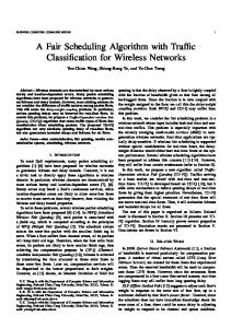
length capacity is 40 Gbps. A packet arrives according to a Poisson process. The average packet length is 400Bytes. The packet length is exponentially distributed, but truncated at 1000Bytes. The time slot size is 20ns, which corresponds to 30% of the average packet length [10]. Every input fiber and wavelength has the same packet arrival rate, and the destination output port of the packet is chosen randomly. 4.2 Evaluation of the Packet Scheduling Algorithms In this subsection, we evaluate the packet scheduling algorithms A0 through A3 described in Section 3. Figures 6 and 7 show the simulation results of packet loss probability dependent on the buffer size BT (the total number of delay lines in the whole switch) in the output buffer type switch and the shared buffer type switch, respectively. As shown in Fig. 6, algorithms A1 through A3 give better performance than algorithm A0 under any traffic load condition, and algorithm A2 gives the best performance. The packet loss probabilities of the shared buffer type switch differ greatly from those of the output buffer type switch especially under the high
10
-1
10-2
10-3
10-4 0.3
Algorithm A0 Algorithm A1 Algorithm A2 Algorithm A3 0.4
0.5
0.6
0.7
0.8
0.9
1
Offered Load
Fig. 9 Packet loss probability (shared buffer type switch, for B = 64)
traffic load condition, as shown in Fig. 7. In the low traffic load condition, algorithm A2 again gives the best performance. In Fig. 7, the performance of the shared buffer type switch decreases when the switch is equipped with a larger buffer size. This is because the queue length becomes long and the possibility of a void space appearing becomes high, as was described in Section 3.3. Figures 8 and 9 show the simulation results for the output buffer type switch and the shared buffer type switch, respectively, when the buffer size BT is fixed at 64. In Fig. 8, it can be observed that the packet loss probability is gradually increased by the higher traffic load. On the other hand, the performance of the shared buffer type switch suddenly deteriorates as shown in Fig. 9. This is because input packets are continuously dropped as the buffer queue length becomes long under the high traffic load condition. The shared buffer type has an advantage in that it requires a smaller buffer size, in the current case, for a number of FDL. However, the performance of the shared buffer type switch deteri-
YAMAGUCHI et al.: SCHEDULING ALGORITHM WITH CONSIDERATION TO VOID SPACE REDUCTION IN PHOTONIC PACKET SWITCH
7 100
100 Algorithm A0 Algorithm A1 Algorithm A2 Algorithm A3
Data Loss Probability
10-2
load = 0.6 -3
10
-4
10
10-5
without Void Reduction
-1
Packet Loss Probability
load = 0.8
-1
10
10
10-2 -3
10
with Void Reduction
-4
10
load = 0.4 0
Fig. 10
64
128
192 256 320 384 Buffer Size BT (= B * N)
448
10-5
512
Data loss probability (output buffer type switch)
Algorithm A1 Algorithm A2 Algorithm A3 Algorithm A1 + Void Reduction Algorithm A2 + Void Reduction Algorithm A3 + Void Reduction
0
4
8
12 16 20 Buffer Size BT (= B)
24
28
32
Fig. 12 Packet loss probability (shared buffer type switch, void space reduction method, load = 0.6)
0
10
100
load = 0.8
Packet Loss Probability
Data Loss Probability
10-1 10-2
load = 0.6 load = 0.4
-3
10
Algorithm A0 Algorithm A1 Algorithm A2 Algorithm A3
10-4 10-5
Fig. 11
0
4
8
12 16 20 Buffer Size BT (= B)
24
28
32
10
-1
10-2
Algorithm A1 (W = 8) 10-3
Algorithm A1 (W = 16) Algorithm A1 (W = 24)
10-4 10-5
0
4
8
Data loss probability (shared buffer type switch)
12 16 20 Buffer Size BT (= B)
24
28
32
Fig. 13 Packet loss probability (shared buffer type switch, increasing the inner wavelengths, load = 0.6)
100 -1
Packet Loss Probability
orates much more than that of the output buffer type switch under high traffic conditions. In the next subsection, we will demonstrate how our void space reduction method improves the performance of the shared buffer type switch. Figures 10 and 11 plot data loss probabilities for the output buffer type and the shared buffer type switch, respectively. Here, data loss probability is defined as the ratio of the total amount of dropped packets to the total amount of input packets. The set of two figures (Figs. 10 and 11) shows the same tendency as the previous set of figures for packet loss probability (Figs. 6 and 7), but algorithm A3 achieves the best result for data loss probability because it gives preference to long packets when assigning the wavelength, thus more data is carried.
10
10-2
Algorithm A1 (W = 8) Algorithm A1 + Void Reduction (W = 8) Algorithm A1 (W = 24)
10-3 10-4 10-5
Algorithm A1 + Void Reduction (W = 24) 0
4
8
12 16 20 Buffer Size BT (= B)
24
28
32
4.3 Evaluation of Void Space Reduction Method
Fig. 14 Packet loss probability (shared buffer type switch, void space reduction method + increasing the inner wavelengths, load = 0.6)
In this subsection, we evaluate our proposed void space reduction method. Figure 12 shows the performance of the shared buffer type switch when the void space reduction method is applied. From this figure, it can
be observed that the performance is dramatically improved by introducing the void space reduction method. And the shared buffer switch outperforms the output
IEICE TRANS. COMMUN., VOL.E86–B, NO.8 AUGUST 2003
8
buffer switch by using the void space reduction method even with the smaller buffer. 4.4 Effects of Increasing the Number of Wavelengths on FDLs Lastly, we last show the effects of increasing the number of wavelengths on FDLs (Wi ). In Fig. 13, we plot the packet loss probability of the shared buffer type switch when the wavelengths on FDLs are increased (Wi = 8, 16, 24). From this figure, it can be observed that when the switch can store more packets in the buffer at one time the performance is actually improved. Of course, the void space reduction method can further improve this performance, and this is demonstrated in Fig. 14. From these two figures, it is clear that the performance of the shared buffer type switch when using the void space reduction method is even better than that of the output buffer type switch. 4.5 Computational Complexity of Packet Scheduling Algorithm In this subsection, we discuss computational complexities of packet scheduling algorithms A0 through A4. In the packet scheduling algorithms, the search for the optimal wavelengths in buffer or output port and the sorting of input packets are the major operations requiring more calculation time. Thus, we only consider the calculation time of the search and the sorting, and ignore the processing time of other operations. Then, the calculation time of Algorithm A0 is negligible because the wavelengths to the packets is assigned in a round-robin fashion in Algorithm A0. We first consider the search time, which is necessary in Algorithm A1, A2, and A3, and in the cases where the void space reduction method is applied to those algorithms. In the search function, since the number of the input ports is N and the number of the multiplexed wavelengths on the port is W , the scheduler needs to search N W times within one slot time at maximum, and to seek W wavelengths in one search. The computational complexity of the search function is given as O(N W 2 ), and if the buffer control algorithm and the void space reduction method are used together, the computational complexity of the search function becomes doubled. Noting that in Algorithm A0, only the search is used and the sort is not, the Algorithm A0 is a reasonable choice, and further introducing the void space reduction method is effective as was shown in Fig. 12. The sort function is additionally required in Algorithms A2 and A3. Since the maximum number of packets which arrives simultaneously is N W , the computational complexity of the sorting function is O(N W log(N W )). Therefore, the search time becomes
dominant as N and/or W become large. In those cases, Algorithms A1 through A3 are not different, and Algorithms A2 or A3 may be chosen. However, as can be observed in Fig. 12, Algorithms A2 and A3 do not attain better performance than Algorithm A1 so much. It implies that Algorithms A1 is efficient in performance and computational complexity. 5.
Conclusions
In this paper, we have evaluated the performance of the shared buffer type switch and the output buffer type switch by applying packet scheduling algorithms. We have compared these two switching architectures taking into account the total number of FDLs. Our simulation results showed that the shared buffer type switch achieves a better performance than the output type switch under low traffic load conditions. On the other hand, under high traffic load conditions, the output buffer type switch gives much better performance than the shared buffer type switch. However, our void space reduction method can improve the performance of the shared buffer type switch even more than that of the output buffer type switch. In future work, we need to evaluate the hardware cost more precisely. And, we need to evaluate the performance of switches using more and better metrics. Acknowledgments This work was supported in part by TAO (Telecommunications Advancement Organization of Japan) under the project “Research and Development Project of Photonic Router for High Speed, High Quality, and Highly Efficient Internet ”. References [1] S. L. Danielsen, B. Mikkelsen, C. Joergesen, T. Durhuus, and K. E. Stubkjaer, “WDM packet switch architectures and analysis of the influence of tuneable wavelength converters on the performance,” IEEE Journal of Lightwave Technology, vol. 15, pp. 219–227, February 1997. [2] S. L. Danielsen, C. Joergesen, B. Mikkelsen, and K. E. Stubkjaer, “Analysis of a WDM packet switch with improved performance under bursty traffic conditions due to tuneable wavelength converters,” IEEE Journal of Lightwave Technology, vol. 16, pp. 729–735, May 1998. [3] D. Hunter, M. C. Chia, and I. Andonovic, “Buffering in optical packet switches,” IEEE Journal of Lightwave Technology, vol. 16, pp. 2081–2094, December 1998. [4] K. L. Hall and K. A. Rauschenbach, “All-optical buffering of 40-Gb/s data packets,” IEEE Photonic Technology Letters, vol. 10, pp. 442–444, March 1998. [5] S. Yao, B. Mukherjee, S. J. B. Yoo, and S. Dixit, “Alloptical packet-swtiched networks: A study of contentionresolution schemes in an irregular mesh network with variable-sized packets,” in Proceedings of OptiComm 2000, pp. 235–246, November 2000. [6] S. L. Danielsen, B. Mikkelsen, C. Joergesen, T. Durhuus, and K. E. Stubkjaer, “Wavelength conversion in optical
YAMAGUCHI et al.: SCHEDULING ALGORITHM WITH CONSIDERATION TO VOID SPACE REDUCTION IN PHOTONIC PACKET SWITCH
9
[7]
[8]
[9]
[10]
[11]
[12]
[13]
packet switching,” IEEE Journal of Lightwave Technology, vol. 16, pp. 2095–2108, February 1997. M. Murata and K. Kitayama, “Ultrafast photonic label switch for asynchronous packets of variable length,” in Proceedings of INFOCOM 2002, vol. 1, pp. 371–380, June 2002. A. Ge, L. tancevski, G. Callegati, and L. Tamil, “WDM fiber delay line buffer control for optical packet switching,” in Proceedings of OptiComm 2000, pp. 247–257, November 2000. F. Callegati, W. Cerroni, and G. Corazza, “Optimization of wavelength allocation in WDM optical buffers,” Optical Networks Magazine, vol. 39, pp. 66–72, November 2001. F. Callegati, “Optical buffers for variable length packets,” IEEE Communications Letters, vol. 4, pp. 292–294, September 2000. L. S. Tamil, F. Masetti, T. McDermott, G. Castanon, A. Ge, and L. Tancevski, “Optical IP routers: Design and performance issues under self-similar traffic,” Journal of High-Speed Networks, vol. 8, no. 1, pp. 59–67, 1999. L. Tancevski, S. Yegnanarayanan, G. Castanon, L. Tamil, F. Masetti, and T. McDermott, “Optical routing of asynchronous, variable length packets,” IEEE Journal on Selected Areas in Communications, vol. 18, pp. 2084–2093, October 2000. P. B. Hansen, S. L. Danielsen, and K. E. Stubkjaer, “Optical packet switching without packet alignment,” in Proceedings of ECOC’98, pp. 591–592, September 1998.
Takashi Yamaguchi received the B.E. degrees in Information and Computer Sciences from Osaka University, Osaka, Japan, in 2001. He is currently a M.E. candidate at the Department of Informatics and Mathematical Sciences, Osaka University, Osaka, Japan. His research work is in the area of high-speed optical networks.
Ken-ichi Baba received the B.E. and M.E. degrees in Information and Computer Sciences from Osaka University, Osaka, Japan, in 1990 and 1992, respectively. After quitting the doctoral course in 1992, he was a Research Associate with Education Center for Information Processing, Osaka University until 1997. He was an Assistant Professor with Electronic and Photonic Systems Engineering, Kochi University of Technology at Kochi in Japan from 1997 until Nov. 1998. He has been an Associate Professor with Computation Center, Osaka University since Dec. 1998. His research interests include broadband communication network, computer communication network, and photonic network systems. He received the D.E. degree from Osaka University in 1995. He is a member of IEICE.
Masayuki Murata received the M.E. and D.E. degree in Information and Computer Sciences from Osaka University, Japan, in 1984 and 1988, respectively. In April1984, he joined Tokyo Research Laboratory, IBM Japan, as a Researcher. From September 1987 to January 1989, he was an Assistant Professor with Computation Center, Osaka University. On February 1989, he moved to the Department of Information and Computer Sciences, Faculty of Engineering Science, Osaka University, he was an Associate Professor from December 1992. He has been a Professor since April 1999. His research interests include computer communication networks, performance modeling and evaluation, and queueing systems. Dr. Murata is a member of the Association for Computing Machinery (ACM), the Internet Society, the Institute of Electronic, Information, and Communication Engineers (IEICE) of Japan, and the Information Processing Society of Japan (IPSJ).
Ken-ichi Kitayama received the B.E., M.E., and Dr.Eng. degrees in communication engineering from Osaka University. Osaka, Japan, in 1974, 1976, and 1981, respectively. In 1976, he joined the NTT Electrical Communication Laboratory. From 1982 to 1983, he was a Research Fellow at the University of California, Berkeley. In 1995, he joined the Communications Research Laboratory, Tokyo, Japan. Since 1999, he has been with Osaka University. He is currently a Professor of the Department of Electronic and Information Systems Engineering, Graduate School of Engineering, Osaka University. His Research interests include photonic networks and radio-on-fiber communications. He has published about 170 papers in refereed journals, written two book chapters, and translated one book. He holds more than 30 patents. He currently serves as an Associate Editor of the IEEE PHOTONICS TECHNOLOGY LETTERS and the IEEE TRANSACTIONS ON COMMUNICATIONS. Dr. Kitayama is a member of the Institute of Electronic, Information, and Communication Engineers (IEICE) of Japan, the Japan Society of Applied Physics, and the Optical Society of Japan. In 1980, he received the Young Engineer Award form the IEICE and in 1985, he received the Paper Award of Optics from the Japan Society of Applied Physics.