sented within a double-linked polyline structure and a self-balancing tree (reflecting the ..... Two tasks in robot navigation are carried out using the multi-aspect.
Schematized Aspect Maps for Robot Guidance Diedrich Wolter and Kai-Florian Richter 1 Abstract. We present an approach to mobile robot guidance. The proposed architecture grants an abstract interface to robot navigation allowing to bridge from perception to high level control. The approach is based upon a comprehensive map representing metric, configurational, and topological knowledge. Robot instruction and localization is dealt with by communicating and reasoning about cyclic ordering information of shape-features.
1
Motivation
Service robots are a growing field of interest and are higly relevant, not only for the research community but also for companies that try to take a share in an emerging market. Within near future, office complexes populated with various heterogenous service robots are a very probable scenario resulting in a range of different problems, for example coordination among the robots and interaction with human users. A key point to instructing robots is to communicate spatial information, for example when commanding a robot to visit a certain place. To provide sufficient control over the various robots, a compatible method of instruction is required for all of them. As a consequence, the spatial representations of the individual robots would need to be compatible with each other. In the presence of different robot systems from various vendors, equipped with different sensors, this is a non-trivial task. Moreover, the chosen method of instruction needs to mediate between the technical abilities of a robot and its often data-driven spatial representation and features desired in a user interaction that are based on more abstract spatial information. To consolidate these different demands we propose a central robot guidance system. A qualitative language, i.e. relational information, is applied for communication with the robots. Allowing for an easy formalization, qualitative information offers a good means for a specification of such a system, which also respects individual robots’ capabilities. In particular, a system based on qualitative information can serve as an interface to a human user. Furthermore, with robot guidance it is possible to restrict the spatial representation of an individual robot to the needs of its specific task, like cleaning of the floor. There is no need to represent the complete working environment within each single robot. Especially within dynamic environments the management, i.e. construction and maintenance, of a spatial representation is a difficult task that has not been solved thoroughly yet [20]. Freeing individual service robots from this burden, our proposed architecture is a slender one. The robot guidance outlined here does not rely upon a precise or even correct map of the environment. Typically, environments are subject to steady changes. Therefore, handling of unreliable, or even conflicting knowledge is of high importance. The proposed guidance 1
Universit¨at Bremen, Germany email: {dwolter,richter}@sfbtr8.unibremen.de
system is well-suited to cope with uncertainty as robust qualitative ordering information gets used.
2
Related Work
Many robot architectures have been proposed that address the construction of a versatile mobile robot. Hereby, the robot’s spatial representation is the key point. Mapping and localization issues have been covered by various authors (see [20] for an overview). It is generally agreed upon that a helpful robot map is not a single-layered representation, but provides different modalities of access, metric information and topological knowledge play key roles here [11, 18]. To respect uncertainty, successful robot architectures typically rely upon a stochastic modeling as a method of localization within a set of possible states [19]. The goal of all approaches mentioned is to gain complete metric knowledge of the environment the robot is located in. With increasing size of environments, the problem gets more difficult as computetime increases and mix-ups in the localization occur. But not all this information may need to be acquired for the construction of a service robot. For example, a robot that is designed to collect garbage in a local surrounding like a single room needs a (spatial) representation that allows for a search strategy, but does not need to know where the room it cleans is located in a larger office complex. Local information is sufficient in guiding a robot from one usage site to another. Thus, with global guidance individual internal representations can be kept at a manageable size. Additionally, it allows to concentrate on a given task, i.e. to only use knowledge needed for the task at hand. Multi-robot scenarios have been investigated and approaches to distributed robot systems have been proposed [5, 4]. However, these approaches rely upon a shared spatial representation that is communicated among the individual robots. Therefore, a compatibility on the lower levels of the internal spatial representation is necessary, which makes it difficult to combine different robot architectures. To obtain an open interface, a more abstract communication is advantageous. Similar to the localization based on regions of same configuration as presented within this approach, Schlieder [17] presents a qualitative approach to ordering of point-like landmarks; all landmarks are assumed visible. Another qualitative approach based on extended—but more abstract—uniquely identifiable features is presented by Barkowsky et al. [2]. In contrast to these approaches we use complex, extended features and only demand some features’ visibility. Moreover, our shape-features need not be uniquely identifiable. Shape processing similar to the features employed in our approach has been proven feasible in the context of robot mapping [14]. Biologically inspired approaches similar to ours exist (e.g., [6]), too. Such view-based approaches typically employ a direct matching of sensor information perceived at certain view-points. Therefore, these approaches do not allow to mediate between different sensors.
Schematic maps are well-suited for communication [7]. As any service robot needs some kind of internal map, communication by means of pictorial information seems promising [8]. We apply a maplike spatial representation in our system to allow for this kind of interaction.
3
Robot Guidance System (RGS)
We propose a single central guidance system that manages several service robots that can be–to some degree–heterogenous. This robot guidance system (RGS) is built on the basis of a map of the working environment. The spatial representation derived from this map can be used for interaction with the robots (see section 6) and is suitable for the different tasks of the given robots as it allows for access in different aspects. With aspects we refer to different kinds of (spatial) information that is representable in a map. Depending on the task, it is possible to focus on certain aspects while ignoring others (cf. [3, 10]). The aspects represented include metric, configurational, and topological information. Accordingly, we term this representation multi-aspect map; its details are presented in section 5. Central to the multi-aspect map is the handling of polygonal shape-features extracted from range information. We cover issues related to them in the next section. The configurational knowledge used in our approach is ordering information, which is a qualitative spatial representation. Qualitative representations summarize similar quantitative states into one qualitative characterization. From a practical viewpoint, a possibly infinite number of states is represented by means of equivalence classes. Therefore, this kind of representation is well suited to handle uncertainty.
4
Shape-Features
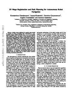
grouped to polylines. A simple heuristic may be used to implement this grouping: Whenever consecutive points are too far apart (a 20cm threshold has been used in our experiments), an object transition is assumed. Range finder information can be ordered in a counterclockwise manner. We will denote the counter-clockwise ordering of objects P before Q as P ≺ Q, meaning that Q directly follows after P . Proceeding this way, we obtain an ordered list of polylines from a range finder scan. Figure 1 illustrates this. These polylines still represent all the information read form the range finder. However, this data contains some noise and is much more precise than actually required by the proposed system. Therefore, a generalization is applied that cancels noise as well as makes the data compact without loosing valuable shape information.
(a)
(b)
(c)
Figure 1. The process of extracting polygonal features from a scan consists of two steps: First, polygonal lines are set up from raw scanner data (a) (1 meter grid, the cross denotes the coordinate system’s origin). The lines are split, wherever two adjacent vertices are too far apart (20 cm). The resulting set of polygonal lines (b) is then simplified by means of discrete curve evolution with a threshold of 2. The resulting set of polygonal lines consists of less data though still capturing the most significant shape information.
4.2
Discrete Curve Evolution (DCE)
The generalization process used for noise cancelation in our approach is called discrete curve evolution (DCE). It has been developed by Latecki & Lak¨amper [13, 14]. This process may be considered as an schematization (see 5.2). It describes a context sensitive process of simplifying a discrete curve by deletion of vertices and allows to reduce the influence of noise and to simplify a shape by removing irrelevant shape features. DCE proceeds in a straightforward manner: From a given polyline, the least relevant vertex is removed. This process is repeated until the least relevant vertex is more relevant than a given threshold. To determine a vertex’ relevance, a measure is defined for a vertex v and its left and right neighbor u and w:
The spatial representation applied in the proposed architecture is based upon polygonal shape-features that represent boundaries of passable space. Using polygonal shape-features allows us to achieve the advantages in feature-based localization while avoiding its shortcomings: A feature-based representation is a compact one. Perceptual information gets interpreted and abstracted to form a feature. Moreover, features offer an object-based access to the information stored. Object-based access to a system’s spatial representation is a fundamental prerequisite for interaction and communication. The drawback of any feature-based approach is the necessity to reliably recognize features from perceptual data. The higher the number of features present in an environment, the more susceptible the recognition process is to any mix-up. Furthermore, if features are sparse (or even not present at all) correct localization is most likely to fail. Therefore, it is necessary to choose features that are distinctive and can be observed from any position within the environment. Shape information provides an excellent choice, as shape offers a great variety. Moreover, a direct link to pictorial information as represented by aspect maps is established (see Section 5). Within a typical indoor scenario, a robot will be able to perceive sufficient information for reliable operation. Processing of polygonal shape features, which we call polylines, is necessary in perception and localization.
where d denotes the Euclidean distance. For vertices that do not have two neighbors no relevance measure is defined. Consequently, endpoints remain fixed. An exemplary result is depicted in figure 1. DCE may be implemented efficiently. As vertices can be represented within a double-linked polyline structure and a self-balancing tree (reflecting the order of relevance measures) simultaneously, the overall complexity is O(n log n). Since we apply DCE to segmented polylines, the number of a polyline’s vertices is much smaller than the number of points read from the sensor.
4.1 Processing Shape-Features
4.3
Let us assume that range information (typically acquired by a laser range finder) is mapped to the Euclidean plane. Reflection points are
A crucial method for localizing a robot is matching the robot’s sensor readings against a map. As the spatial representation used here
K(u, v, w) = |d(u, v) + d(v, w) − d(u, w)|
Similarity of Polylines
relies upon shape features, detecting correspondences between polylines perceived and ones stored in the map is the solution at hand. The matching process relies on a similarity measure for polylines. To each pair of possibly corresponding polylines a measure of matching plausibility is assigned. However, the proposed architecture does not rely exclusively on the correspondence of features, instead it is used alongside with configurational knowledge that poses constraints upon the matching. Therefore, discussion of the actual matching is delayed to section 4.4 and the following description focuses on computing the similarity of two given polylines. The pair of polylines, whose similarity needs to be computed, is on the one hand perceived by the mobile robot and on the other hand extracted from the multi-aspect map. This map is specially designed to be adaptable to any robot’s capabilities. Nevertheless, there may be remarkable differences between the two polylines (e.g., due to noisy perception). Therefore, we need a careful approach to determine similarity. We utilize a similarity measure of polylines originating from Computer Vision [12]. It can easily be adopted to polylines describing environmental features [21]. We briefly summarize the computation of similarity of polylines as presented in [12, 21]. The similarity measure is based on a matching of maximal left- or right-arcuated arcs. Any polyline’s partioning into consecutive nonempty sequences of arcs is called a grouping, if consecutive groups overlap in exactly one line segment. This entails that any grouping covers the whole polyline. Groupings G, H are said to correspond (denoted G ∼ H), if there exist a bijection fG,H between the two groupings such that on the level of maximum arcs only mappings of type 1-to-1, 1-to-many, or many-to-1 exist. Based on a similarity of arcs Sarcs that is presented below, the similarity measure for polylines is defined.
we must also consider that (a) the cyclic ordering ≺ must not be violated and (b) not all features present in one view need to have a counterpart in the other. Whereas the latter may be viewed as a soft constraint, configurational knowledge is reliable and thus poses hard constraints upon the recognition process. By introducing a penalty P for leaving a feature unmatched, we can formulate the computation of views’ similarity by means of dynamic programming similar to aproximate string-matching. Therefore we must linearize the cyclic ordering. This can be done by selecting any feature of one view as the first one, and then considering every linearization of the second view. This yields an overall complexity of O(n3 ) where n denotes the number of features. To be more precise, let us assume that F1 ≺ F2 ≺ . . . ≺ Fn and Fˆ1 ≺ Fˆ2 ≺ . . . ≺ Fˆm are two linearized views. A matrix M of size n × m is set up and is initialized by setting M1,1 to Spoly (F1 , Fˆ1 ) leaving the remains empty. A cell Mi,j may be computed when all cells Mi0 ,j 0 with i0 < i, j 0 < j have been computed. The cell’s value is then given by:
Spoly (g, h) = min Σx∈G Sarcs (x, fG,H (x))
In this section we give further details on the spatial representation we use. As stated earlier, this representation, a map, is multi-aspect. It is suitable for navigational tasks, can be used on different levels of abstraction, and allows for different aspects in access. This multiaspect map is the fundamental representation of our RGS; it is used for localization, path-planning, and interaction with the robots. We termed the set of spatial representations that get used in our RGS multi-aspect map since the different kinds of information correspond to different aspects of the environment. The environmental representation can be accessed depending on a given task, for example topological information for path-planning or metric information for shape matching, and depending on the given context, i.e. the given robot. Our representation is, thus, customized for a specific situation while still originating from a single source. Use of such a multi-aspect map is comparable to the approach taken in the project ’Spatial Structures in Aspect Maps’ [3, 10]; here, the idea is to extract from a given map-like representation all (spatial) information that is needed for a given task and, by focusing on the aspects relevant for the task, providing a cognitively adequate representation. The basis for the multi-aspect map is a representation of the environment; its properties are described in section 5.1. There are three different kinds of information stored in the multi-aspect map: Metric information denotes the shape of the environmental features. The spatial configuration of the features, which corresponds to ordering information, is also explicitely stored in the map. Both kinds of information are needed for robot localization. Topological information is used for path-planning. It is stored as a graph. All kinds of information are present and accessible on different abstraction levels; these levels are adapted to the given robots and their respective sensors. The way we construct the multi-aspect map is detailed in section 5.2.
G∼H
Similarity of arcs is defined in tangent space, a multi-valued step function mapping a curve into the interval [0, 2π) by representing angular directions of line segments only. Furthermore, arc lengths are normalized. Denoting the mapping function by T , the similarity gets defined as follows:
Z Sarcs (c, d) =
1
(Tc (s) − Td (s) + Θc,d )2 ds · (1 + (l(c) − l(d))2 )
0
where l(c) denotes the arc length of c. The constant Θc,d is chosen to minimize the integral (itRrespects for different orientation of curves) 1 and is given by Θc,d = 0 Tc (s) − Td (s)ds. In contrast to the original work, absolute instead of relative size is considered, since this is more adequate in our domain. The correspondence yielding the best similarity is computed using dynamic programming.
4.4
Similarity of Views
On the basis of an individual similarity of polylines we define a similarity of views, cyclic ordered sets of polylines. Whereas similarity of polylines respects only the spatial context of a single polyline, views account for a larger context. It is, thus, a much more distinctive measure. Similarity of views will be the fundamental building block in localizing the robot within the central map and also gets used in the construction process of the map itself. The similarity is based on the individual similarities of corresponding features. Thus, the aim is to find a correspondence relation between features that optimizes the summed up similarity. However,
min S(Fi , Fˆj ) + Mi−1,j−1 , P (Fˆj ) + Mi,j−1 , P (Fi ) + Mi−1,j
�
The first term denotes a 1-to-1 matching of features Fi and Fˆj extending the matching of previous features stored in Mi−1,j−1 . The second and third term addresses the possibility that a feature is not matched at all. The penalty measure P is chosen to scale linearly with the size of the feature, as it is much more likely to overlook a small object than a larger one.
5
Multi-Aspect Map
5.1
Properties of the Map
A map of the environment is the basic representation of the RGS. The map’s structure is polygonal, i.e. its basic elements are polylines. Such a map can be obtained in different ways. One way is to use an existing map, i.e. an electronic version of a building’s blueprint. This requires that all elements of the dataset can be addressed directly, i.e. it is possible to access objects individually, and that such an existing dataset is rich enough to contain all the information needed for the different tasks. The map can also be obtained by using a robot that explores the environment and builds a map of it. Many approaches to robot mapping have been proposed [20, 9]. Even though they typically rely either on simple line segments or uninterpreted data, they can be extended to deal with polygonal lines, or polylines may be extracted from their output. An example of such map extracted from laser range finder data is depicted in figure 2.
5.2
Constructing a Multi-Aspect Map
Construction of the multi-aspect map is a three-step process. First, we construct the maps designated for the different robots, i.e. schematizing the map of the environment to an adequate abstraction level. Next, we determine for each schematized map a graph reflecting the envionment’s topological structure. Based on this graph we then calculate regions of similar order and, thus, partition the plane.
5.2.1
Schematizing maps
Roughly speaking, map schematization describes a simplification— or even an elimination—of map objects, respecting essential spatial relations. Schematizing maps, hence, involves simplification of shape information. Complex polylines are simplified to obtain simpler ones that still show off the most important shape information while hiding the details. To simplify shapes, various techniques have been proposed. The DCE process as presented in section 4.2 is one promising approach to shape simplification. It has been successfully applied to shape simplification in map schematization [1]. Besides DCE, other approaches to shape simplification have been proposed, too. For example, the Curvature Scale Space proposed by Mokhatarian et al. is based on a simplification process’ history [15, 16]; a Gaussian convolution filter is applied to accomplish the simplification. Simplification by means of smoothening changes shapes globally, whereas simplification by vertex removal like in DCE is composed out of local changes. Since any simplification must be checked for admissibility, e.g., to prevent violation of topological constraints (see below), DCE’s discrete structure is advantageous here. Due to the more complex structure of map schematization compared to simplification of a single polyline, the DCE process needs to be adapted, though. On the one hand, not every point of the structure can be removed, for example points that belong to multiple objects. They must be preserved to retain the fact that multiple objects meet at this point. On the other hand, as the spatial information has to remain correct for the different tasks to remain accomplishable, we take into account relational information of the map’s entities. We need to take care that by removing vertices there does not occur a violation of any relational information. After an evolution step may, for example, (parts of) an entity be resided left to another entity while it was located right to it prior to this step, or two entities may now overlap. For further details of the necessary extensions to DCE for map schematization see [1].
(a)
(b)
Figure 2.
(c)
The base map (a), and two different schematization levels: medium (b) and maximum (c)
Additionally, as small objects do not provide relevant features they get removed from the map. Just like the degree of schematization, the size threshold depends on the sensors used by the different robots. Figure 2 depicts some schematization levels as an example. Theoretically, the maximum number of different abstraction levels corresponds to the number of inner points of all polygonal lines as the process of discrete curve evolution is stepwise and removes one vertex in each step. Practically, the actual number of different abstraction levels that get stored in the RGS is much smaller. Schematized maps are only needed on certain levels of abstraction; these levels are determined by the robots’ perceptual abilities. These abilities are taken into account when setting the levels’ DCE thresholds. Each marks a level of adequate abstraction. All schematization levels in-between are deemed qualitatively equal to either of them and are not considered. Thus, although quantitatively the number of possible maps is quite high, the number of maps that really get constructed is rather low due to the qualitative abstraction involved.
5.2.2
Regions of similar order
Next, we determine a graph embedded in the map that reflects the environment’s topological structure. We consider structure from a more abstract point of view, as we are only interested in noticeable differences, for example when moving through a door into another room. The graph is calculated based on the schematized map and gets used for path-planning (see 5.3). For example, Voronoi graphs are suitable for this purpose [18]. This graph is taken as the basis for determining regions of similar order: The graph is said to intersect with the boundary of a region whenever traversing its edges yields a high dissimilarity of views at nearby positions (see 4.4). Practically, computing the similarity for nearby views along the graph’s edges is performed by a subsampling of similarity values at a given number of locations on the edges. Each time the value exceeds a given threshold a new region is generated. For each region a single, prototypical view is stored in the map, which gets used in the localization process.
5.3
Using the Multi-Aspect Map for Robot Navigation
Two tasks in robot navigation are carried out using the multi-aspect map, namely qualitative localization and topological path-planning. Prior to using the map for communicating with a robot, the adequate level of schematization needs to be chosen. We select the appropriate level from the multi-aspect map regarding the level of generalization
used by the robot for feature extraction. This ensures that features stored in the map are perceivable to the robot, i.e. they are not too small to be detected by the robot when not close-by. The map’s topological aspect is used to plan a robot’s path from a given location to a goal region. We calculate a qualitative path by means of graph-search determining the regions the robot passes by. A prerequisite for successful navigation is that the robot can be localized; we describe this process in detail in the next section.
6
Instructing a Robot
To command a robot to a given area of the environment, the robot needs first of all to be localized within the multi-aspect map in order to plan a path. Localization combines the similarity of shape features with configurational knowledge. It is covered in section 6.1. Knowing the robot’s position within the map, a path that leads the robot to its goal region can be computed. As will be presented in section 6.2 a single motion primitive is sufficient to guide the robot along this path.
6.1
Localization
For the RGS it is sufficient to localize a robot qualitatively. The term qualitative localization as opposed to metric localization is chosen to stress that only information required for the guidance task is used. The robot’s position is represented by qualitative regions of similar order. Hence, localization means to recognize the region a robot currently visits. Similarity of views (see section 4.4) is the clue here. Therefore, the approach to localization taken here relates to viewbased approaches (cf. [6]); however, the presented approach is more abstract, since sensor information is always interpreted first. Such a more abstract approach is advantageous here, as different robots utilizing different sensors (e.g., laser range finder mounted at differing heights) need to be localized. To localize the robot, individual plausibilities are computed for the robot being in a particular region by determining the similarity between the prototypical view associated with the individual region and the view perceived by the robot. These plausibility values can easily be coupled with a stochastical approach to localization like Markov localization (cf. [19]). Plausibility values are therefore scaled such that the overall sum yields 1. The robot is said to visit the region which has currently the highest belief state. 11.21 14.86
14.86 0.35
0.00
6.2
Instruction
Once the robot is localized, instruction can be realized with just one motion primitive that needs to be implemented into each mobile robot: moving the robot inbetween two features it has perceived. It moves along until the order of features changes, i.e. a feature becomes invisible or a new feature emerges and, thus, probably a new region is entered. This motion primitive is sufficient to guide the robot from cell to cell, i.e. along the different regions of similar order; its path is determined using the topological graph (see 5.2.2). For the purpose of localization the belief state is updated accordingly.
7
Conclusion
In this paper, we proposed a central system that can be used to guide various service robots acting in an environment. It allows to integrate different kinds of service robots within a larger context, while offering a single interface for the human user to all robots involved. This single interface is one of the system’s main advantages, as a user does not need to remember and to switch to different interaction modes depending on the robot currently addressed. The specifics of the robot remain abstract to the user. Interaction is cognitively adequate since the user can concentrate on the task the robot is about to perform. We use a single spatial representation—a multi-aspect map—in the system; this representation allows to access just the information needed for a given navigational task and robot, namely metric, ordering, or topological information on different abstraction levels. This is another main advantage of the proposed architecture: reasoning about the environment, i.e. localization and navigation, takes place on a qualitative level. We apply a partitioning of the environment in regions of similar order, which is a novel approach. It is robust but detailed. We employ these regions and a matching of shapefeatures in robot localization. We can, thus, perform this localization on a qualitative level, which is very robust, keeps the communication compact, and allows for an efficient path execution algorithm. The prime focus of this paper has been to present the general structure of our proposed architecture and to point out its advantages. While individual aspects have already been implemented, future work comprises the integration of these parts and an evalutation of the whole system.
Acknowledgements This work is part of the projects R3-[Q-Shape] and I2-[MapSpace] of the Transregional Collaborative Research Center (SFB/TR 8) Spatial Cognition funded by the Deutsche Forschungsgemeinschaft (DFG). We would like to thank Prof. Latecki for discussion and comments.
11.39 20.02 27.31
(a)
(b)
(c)
(d)
Figure 3. (a): An excerpt from the utilized path network shown on the medium level schematization. Blocks denote the borderline of regions of similar order. (b): The prototypical view associated with the network’s lowest segment of (a). The shape-features extracted from a scan taken at the lower end of the hallway (c) are matched against the prototypical views stored for each region. The membership probability in % is given in (d). As can be observed, matching a single view already yields the right localization.
REFERENCES [1] Barkowsky, T., Latecki, L.J.,& Richter, K.-F. (2000). Schematizing maps: Simplification of geographic shape by dicrete curve evolution. In: C. Freksa, W. Brauer, C. Habel, & K.F. Wender (eds.), Spatial Cognition II (pp. 41–53). Berlin: Springer. [2] Barkowsky, T., Berendt, B., Egner, S., Freksa, C., Krink, T., R¨ohrig, T., & Wulf, A. (1994). The REALATOR: How to construct reality. In: ECAI’94 Workshop W12 Spatial and Temporal Reasoning. [3] Berendt, B., Barkowsky, T., Freksa, C., & Kelter, S. (1998). Spatial representation with aspect maps. In: C. Freksa, C. Habel, & K.F. Wender, Spatial Cognition (pp. 157–175). Berlin: Springer. [4] Burgard, W., Moors, M., Fox. D., Simmons, R., & Thrun, S. (2000). Collaborative multi-robot exploration. In: Proc. of the IEEE International Conference on Robotics & Automation (ICRA).
[5] Cohen, W. (1996). Adaptive mapping and navigation by teams of simple robots. Journal of Robotics & Autonomous Systems 18:411-434. [6] Franz, M.O., B. Sch¨olkopf, H.A. Mallot, &H.H. B¨ulthoff (1998). Learning view graphs for robot navigation. Autonomous Robots, 5, pp. 111–125 [7] Freksa, C. (1999). Spatial aspects of task-specific wayfinding maps – A representation-theoretic perspective. In: J.S. Gero & B. Tversky (eds.), Visual and Spatial Reasoning in Design (pp. 15–32). Key Centre of Design Computing and Cognition, University of Sidney. [8] Freksa, C., Moratz, R., & Barkowsky, T. (2000). Schematic maps for robot navigation. In: C. Freksa, W. Brauer, C. Habel, & K.F. Wender (eds.), Spatial Cognition II (pp. 100–114). Berlin: Springer. [9] Gutmann, J.-S. & Konolige, K. (1999). Incremental Mapping of Large Cyclic Environments. In: International Symposium on Computational Intelligence in Robotics and Automation (CIRA’99), Monterey. [10] Klippel, A, Richter, K.-F., Barkowsky, T. & Freksa, C. The Cognitive Reality of Schematic Maps. In: A. Zipf, T., & L. Meng (eds.), Map-based Mobile Services – Theories, Methods and Implementations. Berlin: Springer. to appear. [11] Kuipers, B. (2000). The Spatial Semantic Hierarchy. Artificial Intelligence 119:191–233. [12] Latecki, L.J. & Lak¨amper, R. (2000): Shape Similarity Measure Based on Correspondence of Visual Parts. IEEE Trans. Pattern Analysis and Machine Intelligence (PAMI) 22(10):1185–1190. [13] Latecki, L.J. & Lak¨amper, R. (1999). Convexity rule for shape decomposition based on discrete contour evolution. Computer Vision and Image Understanding 73:441–454. [14] Latecki, L.J., Lak¨amper, R., & Wolter, D. (2003). Shape Similarity and Visual Parts. Proceedings of Discrete Geometry for Computer Imagery, Naples, Italy, November 2003. [15] Mokhtarian, F. & Bober, M. (2003). Curvature Scale Space Representation: Theory, Applications and MPEG-7 Standardization. Kluwer Academic Press. [16] Mokhtarian, F. & Mackworth, A. K. (1992). A theory of mulitscale, curvature-based shape representation for planar curves. IEEE Transactions on Pattern Analysis and Machine Intelligence, 14(8):789–805. [17] Schlieder, C. (1995). Reasoning about ordering, In: A. Frank and W. Kuhn (eds.), Proceedings of the 3rd International Conference on Spatial Information Theory. [18] Thrun, S. (1998). Learning Metric-Topological Maps for Indoor Mobile Robot Navigation. Artificial Intelligence, 99:21–71. [19] Thrun, S. (2000). Probabilistic Algorithms in Robotics. Artifical Intelligence, 21(4): 93–109. [20] Thrun, S. (2002). Robot Mapping: A Survey, In: G. Lakemeyer & B. Nebel (eds.), Exploring Artificial Intelligence in the New Millenium. Morgan Kaufmann. [21] Wolter, D. and Latecki, L. J. (2004). Shape Matching for Robot Mapping, In: Zhang, C., Guesgen, H.W., and Yeap,W.K., Proceedings of 8th Pacific Rim International Conference on Artificial Intelligence, Auckland, New Zealand, to appear