9th IFAC symposium on Control of Power and Energy Systems 9th IFAC symposium on Control of Power and Energy Systems Indian Institute of Technology 9th symposium on 9th IFAC IFAC symposium on Control Control of of Power Power and and Energy Energy Systems Systems Indian Institute of Technology 9th IFAC symposium on Control and Energy Systems December 9-11, 2015. Delhi, Indiaof Power Indian Institute of Technology Available online at www.sciencedirect.com Indian Institute of Technology December 9-11, 2015. Delhi, India Indian Institute of Technology December December 9-11, 9-11, 2015. 2015. Delhi, Delhi, India India December 9-11, 2015. Delhi, India
ScienceDirect
IFAC-PapersOnLine 48-30 (2015) 001–006
Coordinated Voltage Control of Weak Coordinated Voltage Control of Weak Coordinated Voltage Control of Coordinated Voltage Control of Weak Weak Sub-transmission Networks Considering Sub-transmission Networks Considering Sub-transmission Networks Considering ⋆ Sub-transmission Networks Considering Wind Power Variability ⋆⋆ Wind Power Variability Wind Power Variability Wind Power Variability ⋆
Zhiyuan Tang ∗∗ David J. Hill ∗∗ Tao Liu ∗∗ Zhiyuan Tang David J. Hill Tao Liu ∗ ∗ ∗ ∗ ∗ ∗ Zhiyuan Tang J. Hill ∗ David ∗ Tao Zhiyuan Tang David J. Hill Tao Liu Zhiyuan Tang David J. Hill Tao Liu Liu ∗ ∗ ∗ The University of Hong Kong, Hong Kong The University of Hong Kong, Hong Kong ∗ ∗ University of (e-mail: zytan,dhill,
[email protected]) ∗ The The University of Hong Hong Kong, Kong, Hong Hong Kong Kong The University of Hong Kong, Hong Kong (e-mail: zytan,dhill,
[email protected]) (e-mail: zytan,dhill,
[email protected]) (e-mail: zytan,dhill,
[email protected]) (e-mail: zytan,dhill,
[email protected]) Abstract: In this paper, a novel coordinated control method is proposed to handle the negative Abstract: In In this paper, paper, aa novel novel coordinated control control method method is is proposed to to handle the the negative Abstract: voltage impacts on paper, weak sub-transmission systems, which are caused by wind power fluctuations. Abstract: In this a coordinated control method is proposed to handle the negative Abstract: In this this paper, a novel novel coordinated coordinated control method is proposed proposed to handle handle the negative negative voltage impacts on weak sub-transmission systems, which are caused by wind power fluctuations. voltage impacts on weak sub-transmission systems, which are caused by wind power fluctuations. Firstly, wind variations are divided into large and small fluctuations. Then, according to the voltage impacts on weak sub-transmission systems, which are caused by wind power fluctuations. voltage impacts on weak sub-transmission systems, which are caused by wind power fluctuations. Firstly, wind variations are divided into large and small fluctuations. Then, according to the Firstly, wind variations are divided into large and small fluctuations. Then, according to different control characteristics of on-load tap changers (OLTCs) and static compensators Firstly, wind variations are divided into large and small fluctuations. Then, according to the Firstly, wind variations are divided into large and small fluctuations. Then, according to the the different control characteristics of on-load tap changers (OLTCs) and static compensators different control of on-load tap changers static compensators (STATCOMs), thecharacteristics OLTCs are used to minimize the impacts(OLTCs) caused byand large fluctuations, while different control characteristics of on-load tap changers (OLTCs) and static compensators different control characteristics of on-load tap changers (OLTCs) and static compensators (STATCOMs), the OLTCs are used to minimize the impacts caused by large fluctuations, while (STATCOMs), the OLTCs are used to minimize the impacts caused by large fluctuations, while the STATCOMsthe areOLTCs used toare eliminate impacts by small fluctuations. The model (STATCOMs), used minimize the impacts by fluctuations, while (STATCOMs), used to to the minimize theintroduced impacts caused caused by large large fluctuations, while the STATCOMs STATCOMsthe areOLTCs used to toare eliminate the impacts introduced by small small fluctuations. The model model the are used eliminate the impacts introduced by fluctuations. The predictive control (MPC) and a consensus based distributed control techniques are adopted the STATCOMs are used to eliminate the impacts introduced by small fluctuations. The model the STATCOMs are(MPC) used toand eliminate the impacts introduced by small fluctuations. The model predictive control a consensus based distributed control techniques are adopted predictive control (MPC) and consensus based distributed control are to design the control schedules OLTCs and STATCOMs, It is shown that by predictive control (MPC) and a based distributed control techniques are adopted predictive control (MPC) and a aof consensus based distributedrespectively. control techniques techniques are adopted adopted to design design the the control schedules ofconsensus OLTCs and and STATCOMs, respectively. It is is shown shown that by to control schedules of OLTCs STATCOMs, respectively. It that the coordination of OLTCs and STATCOMs, voltage violations of points of interconnection to design the control control schedules ofSTATCOMs, OLTCs and and voltage STATCOMs, respectively. Itofis is interconnection shown that that by by to design the schedules of OLTCs STATCOMs, respectively. It shown by the coordination of OLTCs and violations of points the coordination of OLTCs and STATCOMs, voltage violations of points of interconnection (POIs) are eliminated, and voltage fluctuationsvoltage at unregulated buses are mitigated. The the coordination of and violations of of the coordination of OLTCs OLTCs and STATCOMs, STATCOMs, voltage violationsload of points points of interconnection interconnection (POIs) are eliminated, and voltage fluctuations at unregulated load buses are mitigated. The (POIs) are eliminated, and voltage fluctuations at unregulated load buses are mitigated. The effectiveness of our proposed controlfluctuations scheme is presented throughload a case study the modified (POIs) are and at buses are mitigated. The (POIs) are eliminated, eliminated, and voltage voltage at unregulated unregulated buses are on mitigated. The effectiveness of our our proposed proposed controlfluctuations scheme is is presented presented throughload case study on the modified modified effectiveness scheme through aaaa to case on the IEEE 14-bus of test system withcontrol a real wind power profile. According thestudy simulation results, it effectiveness of our proposed control scheme is presented through case study on the modified effectiveness of our proposed control scheme is presented through case study on the modified IEEE 14-bus test system with a real wind power profile. According to the simulation results, it IEEE 14-bus test system with a real wind power profile. According to the simulation results, it turns out that the proposed approach can reduce the operation number of OLTCs significantly, IEEE 14-bus test system with a real real wind wind power profile. profile. According to the the simulation results, it it IEEE 14-bus test system with a power According to simulation results, turns out that the proposed approach can reduce the operation number of OLTCs significantly, turns out the proposed approach can operation number of and decrease capacity of STATCOMs dramatically comparison withsignificantly, the existing turns out that the proposed approach can reduce the operation number of OLTCs turns out that thatthe therequired proposed approach can reduce reduce the the operation by number of OLTCs OLTCs significantly, and decrease decrease the required capacity of STATCOMs STATCOMs dramatically by comparison withsignificantly, the existing and the required capacity of dramatically by comparison with the control scheme. and decrease the required capacity of STATCOMs dramatically by comparison with the existing and decrease the required capacity of STATCOMs dramatically by comparison with the existing existing control scheme. control control scheme. scheme. control scheme. © 2015, IFAC (International Federation of Automatic Control) Hosting by Elsevier Ltd. All rights reserved. Keywords: Coordinated voltage control, wind power, sub-transmission system, on-load tap Keywords: Coordinated Coordinated voltage voltage control, control, wind wind power, power, sub-transmission sub-transmission system, system, on-load on-load tap tap Keywords: changer, static compensator, model predictive control,sub-transmission distributed control. Keywords: Coordinated voltage control, wind power, power, sub-transmission system, on-load on-load tap tap Keywords: Coordinated voltage control, wind system, changer, static compensator, model predictive control, distributed control. changer, static compensator, model predictive control, distributed control. changer, static compensator, model predictive control, distributed control. changer, static compensator, model predictive control, distributed control. 1. INTRODUCTION become worse in a weak sub-transmission system. Due 1. INTRODUCTION INTRODUCTION become worse in a weak sub-transmission system. Due 1. become worse in sub-transmission system. to the high resistance ratio, the voltage magnitudes are 1. INTRODUCTION become worse in weak sub-transmission system. Due 1. INTRODUCTION become worse in aaa weak weak sub-transmission system. Due Due to the high resistance ratio, the voltage magnitudes are the high resistance ratio, the voltage magnitudes are not only closely coupled with reactive power but also to the high resistance ratio, the voltage magnitudes are Considering the huge environmental advantages, it has to to the high resistance ratio, the voltage magnitudes are not only closely coupled with reactive power but also Considering the the huge huge environmental environmental advantages, advantages, it it has has not only closely coupled with reactive power but also active power. Accordingly, the wind power fluctuations can Considering not only closely coupled with reactive power but also been a trend that more and more distributed renewable Considering the huge environmental advantages, it has only closely coupled the with reactive power but also active power. Accordingly, wind power fluctuations can Considering the huge environmental advantages, it has not been a trend that more and more distributed renewable active power. Accordingly, the power fluctuations can the voltage profiles voltage regbeen trend more and more renewable active power.influence Accordingly, the wind wind power and fluctuations can energyaaa sources (RESs) the traditional power significantly been trend that that morewill andparallel more distributed distributed renewable power. Accordingly, the wind power fluctuations can significantly influence the voltage profiles and voltage regbeen trend that more and more distributed renewable energy sources sources (RESs) will parallel the traditional traditional power active significantly influence the voltage profiles and voltage regulators (VRs). Moreover, the irregular network topology energy (RESs) will parallel the power significantly influence the voltage profiles and voltage regsystem generation at all voltage levels. In particular, due to energy sources (RESs) will parallel the traditional power significantly influence the voltage profiles and voltage regulators (VRs). Moreover, the irregular network topology energy sources (RESs) parallel the power system generation generation at all all will voltage levels. In traditional particular, due due to ulators (VRs). Moreover, the irregular network topology of a sub-transmission network such influences more system In to (VRs). the irregular network topology the economics andat convenience, the number of wind due farms system generation at all voltage voltage levels. levels. In particular, particular, due to ulators ulators (VRs). Moreover, Moreover, the makes irregular network topology of aa sub-transmission network makes such influences more system generation at all voltage levels. In particular, to the economics and convenience, the number of wind farms of sub-transmission network makes such influences complicated. the economics and convenience, the number of wind farms of a sub-transmission network makes such influences more connected to main grid through sub-transmission systems the economics and convenience, the number of wind farms of a sub-transmission network makes such influences more more the economics and convenience, the number of wind farms complicated. connected to main grid through sub-transmission systems complicated. connected to main grid through sub-transmission systems complicated. is growing. connected to main grid through sub-transmission systems complicated. connected to main grid through sub-transmission systems Voltage violation issues have been studied by numerous is growing. Voltage violation issues have been studied by numerous is growing. is growing. Voltage issues been studied by see Carvalho et al. (2008), Mokhtari et al. is growing. Voltage violation issues have been studied by numerous However, distributed wind farms at sub-transmission levels approaches, Voltage violation violation issues have have been studied by numerous numerous approaches, see Carvalho et al. (2008), Mokhtari et al. However, distributed wind farms at sub-transmission levels approaches, see Carvalho et al. (2008), Mokhtari et (2013), and Robbins et al. (2013) for example. A distributHowever, distributed at levels approaches, see Carvalho Carvalho et al. al. for (2008), Mokhtari et al. al. can introduce reverse wind powerfarms flow into transmission systems However, distributed wind farms at sub-transmission sub-transmission levels approaches, see et (2008), Mokhtari et al. (2013), and Robbins et al. (2013) example. A distributHowever, distributed wind farms at sub-transmission levels can introduce reverse power flow into transmission systems (2013), and Robbins al. (2013) for example. A distributed control scheme is et proposed in Carvalho et al. (2008) to can introduce reverse power flow into transmission systems (2013), and Robbins et al. (2013) for example. A distributin ways not allowed for in the original power system design. can introduce reverse power flow into transmission systems (2013), and Robbins et al. (2013) for example. A distributed control scheme is proposed in Carvalho et al. (2008) to can introduce reverse into transmission in ways ways not allowed allowed forpower in the theflow original power system systemsystems design. mitigate ed control scheme is proposed in Carvalho et al. (2008) to voltage rise problems.in The authors in Mokhtari in not for in original power control scheme is proposed Carvalho et al. (2008) to Asways a result, interconnections of distributed winddesign. farms ed in ways not allowed for in the original power system design. ed control scheme is proposed in Carvalho et al. (2008) to mitigate voltage rise problems. The authors in Mokhtari in not allowed for in the original power system design. As aa result, result, interconnections interconnections of of distributed distributed wind wind farms farms mitigate voltage rise problems. The authors in Mokhtari et al. (2013) propose a robust control scheme based on As mitigate voltage rise problems. The authors in Mokhtari introduce operation situations that did not occur in the As a result, interconnections of distributed wind farms mitigate voltage rise problems. The authors in Mokhtari et al. (2013) propose a robust control scheme based on As a result, interconnections of distributed wind in farms introduce operation situations that did not occur the al. aaa robust scheme based on localized and propose distributed controlcontrol strategies to deal introduce operation did occur in et al. (2013) (2013) propose robust control scheme basedwith on past, and the systemsituations is exposedthat to more severe problems introduce operation situations that did not not occur in the the et et al. (2013) propose robust control scheme based on localized and distributed control strategies to deal with introduce operation did not occur in the past, and and the the systemsituations is exposed exposedthat to more more severe problems localized and distributed control strategies to deal with voltage rise issues. In Robbins et al. (2013), a two-level past, system is to severe problems localized and distributed control strategies to deal with caused by the inherent variability and intermittence of past, and the system is exposed to more severe problems localized and distributed control strategies to deal with voltage rise issues. In Robbins et al. (2013), a two-level past, is exposed to more severe problems causedand bythe thesystem inherent variability and intermittence intermittence of control scheme rise In et two-level is proposed to prevent voltage aaaviolations. caused by variability of voltage rise issues. In Robbins et al. (2013), two-level wind, especially in the case of highand penetration of wind caused by the the inherent inherent variability and intermittence of voltage voltage rise issues. issues. In Robbins Robbins et al. al. (2013), (2013), two-level control scheme is proposed to prevent voltage violations. caused by the inherent variability and intermittence of wind, especially in the case of high penetration of wind control scheme is proposed to prevent voltage violations. As one of the most successful model based on closed-loop wind, especially in the case of high penetration of wind control scheme is proposed to prevent voltage violations. power. wind, especially in the case of high penetration of wind scheme is proposed to model prevent voltage violations. As one of the most successful based on closed-loop wind, especially in the case of high penetration of wind control power. As one the successful model based on control scheme, model predictive control (MPC) has been power. As one of of the most most successful model based on closed-loop closed-loop power. one of the most successful model based on closed-loop control scheme, model predictive control (MPC) has been power. Among these problems, voltage issues are one of the main As control scheme, model predictive control (MPC) has been applied to solve various problems resulted by high penetracontrol scheme, model predictive control (MPC) has been Among these problems, voltage issues are one of the main control scheme, model predictive control (MPC) has been applied to solve various problems resulted by high penetraAmong these problems, voltage issues are one of the main impacts on sub-transmission networks introduced by the Among these problems, voltage issues are one of the main applied to solve various problems resulted by high penetration of distributed generation (DG) for its receding horizon Among these problems, voltage issues are one of thebymain applied to solve various problems resulted by high penetraimpacts on sub-transmission networks introduced the applied to solve various problems resulted by high penetration of distributed generation (DG) for its receding horizon impacts on sub-transmission networks introduced by the wind power variability. As is networks pointed out in Baghsorkhi impacts on sub-transmission sub-transmission introduced by the the and tion of distributed generation (DG) for horizon multi-step prediction. example, a demand side impacts on introduced by tion of distributed generationFor (DG) for its its receding receding horizon wind power power variability. As As is is networks pointed out out in Baghsorkhi Baghsorkhi of distributed generation (DG) for its receding horizon and multi-step prediction. For example, aa demand side wind variability. pointed in and Hiskens (2012b), voltage violations at points of inter- tion wind power variability. As is pointed out in Baghsorkhi and multi-step prediction. For example, demand side control is proposed in Zong et al. (2012) considering high wind power variability. As is pointed out in Baghsorkhi and multi-step multi-step prediction. For example, demand high side and Hiskens Hiskens (2012b), (2012b), voltage voltage violations violations at at points points of of interinter- and prediction. For example, aa demand side control is proposed in Zong et al. (2012) considering and connection (POIs) and voltage fluctuations at unregulated and Hiskens (2012b), voltage violations at points of interis proposed in Zong et al. (2012) considering high wind penetration. In Valverde and Van Cutsem (2013), and Hiskens(POIs) (2012b), voltage violations at points of inter- control control is proposed in Zong et al. (2012) considering high connection and voltage fluctuations at unregulated control is proposed in Zong et al. (2012) considering high wind penetration. In Valverde and Van Cutsem (2013), connection voltage at load buses (POIs) are theand two main fluctuations negative impacts. Things wind connection (POIs) and voltage fluctuations at unregulated unregulated penetration. Valverde and Van (2013), authors presentsIn based voltage control strategy connection voltage at unregulated wind penetration. In Valverde and Van Cutsem (2013), load buses buses (POIs) are the theand two main fluctuations negative impacts. impacts. Things the wind penetration. Inaa MPC Valverde and Van Cutsem Cutsem (2013), the authors presents MPC based voltage control strategy load are two main negative Things load buses are the two main negative impacts. Things the authors presents a MPC based voltage control strategy to maintain voltages within predefined limits considering load buses are the two main negative impacts. Things the authors presents a MPC based voltage control strategy the authors presents a MPC based voltage control strategy to maintain voltages within predefined limits considering ⋆ The work described in this paper was fully supported by a grant to maintain voltages within predefined limits considering high penetration of DGs. ⋆ The work described in this paper was fully supported by a grant to maintain voltages within to maintain voltages within predefined predefined limits limits considering considering ⋆ high penetration of DGs. from Research Grants Council the Hong Kong Special Ad⋆ The work described in paper was fully supported by Thethe work described in this this paper of was fully supported by a a grant grant ⋆ high penetration of DGs. high penetration of DGs. from the Research Grants Council of the Hong Kong Special AdThe work described in this paper was fully supported by a grant high penetration of DGs. ministrative Region under Theme-based Research Scheme through from from the the Research Research Grants Grants Council Council of of the the Hong Hong Kong Kong Special Special AdAd-
ministrative RegionGrants under Theme-based Scheme through from the Research Council of theResearch Hong Kong Special AdProject No. T23-701/14-N. ministrative Region ministrative Region under under Theme-based Theme-based Research Research Scheme Scheme through through Project No. T23-701/14-N. ministrative Region under Theme-based Research Scheme through Project No. T23-701/14-N. Project Project No. No. T23-701/14-N. T23-701/14-N. Copyright © 2015, 2015 IFAC 1 Hosting by Elsevier Ltd. All rights reserved. 2405-8963 © IFAC (International Federation of Automatic Control) Copyright © 2015 IFAC 1 Copyright ©under 2015 responsibility IFAC 1 Control. Peer review of International Federation of Automatic Copyright © 2015 IFAC 1 Copyright © 2015 IFAC 1 10.1016/j.ifacol.2015.12.344
IFAC CPES 2015 2 December 9-11, 2015. Delhi, India
Zhiyuan Tang et al. / IFAC-PapersOnLine 48-30 (2015) 001–006
It is shown in Carvalho et al. (2008) and Baghsorkhi and Hiskens (2012b) that strict local control with continuous controllers may lead to the potential higher frequency of on-load tap changers (OLTCs). However, the interactions between local voltage control schemes at POIs with continuous controllers and the operation of discrete OLTCs are not considered in these works. Thus, coordination between different controllers should be considered to achieve an optimal operation.
(2)
On the other hand, coordinated control has shown its effectiveness in solving traditional voltage problems in power systems (Li et al. (2004) and Ma and Hill (2014). In Ma and Hill (2014)), capacitors, OLTCs, and load shedding are coordinated to provide emergency voltage control. These works do not consider impacts caused by RESs, and moreover, they use an assumption that the action time scales (from receiving signal to taking effective action) of controllers used are close enough. In fact, the action time scales of diverse VRs can be very different. For example, it may take a few minutes for OLTCs while it only takes a few milliseconds or even less for static compensators (STATCOMs).
(3)
Inspired by these issues, a novel coordinated voltage control strategy is proposed to address the aforementioned voltage problems of a weak sub-transmission network and the corresponding control challenges. OLTCs and STATCOMs are the controllers used in this paper. Wind power variation is divided into large and small wind fluctuation and corresponding voltage impacts are handled by OLTCs and STATCOMs, respectively. Through coordination of OLTCs and STATCOMs, the voltage violation problems at POIs are eliminated and the voltage fluctuations of unregulated load buses are mitigated. Compared with the existing control scheme, our proposed control scheme also has advantages with more control flexibility and much less control cost.
(4)
(5)
The rest of the paper is organized as follows. Section 2 describes the proposed coordinated control strategies while a test system is introduced in Section 3. The effectiveness and advantages of our proposed approach is showed in Section 4. The main conclusions are presented in Section 5.
have large dead bands. Based on this, we decompose wind power fluctuations as large and small wind power fluctuations. The actions of OLTCs are scheduled to deal with significant voltage variations of large wind fluctuations, and STATCOMs are utilised to handle remaining slight voltage influences caused by small wind fluctuations. Predicted wind power is used to make the control schedules of OLTCs. Considering the influence of prediction errors and dead bands of OLTCs, all bus voltages are regulated by OLTCs to a predefined range which is narrower than the acceptable range of operation. Thus, when the worst scenario happens, which means the prediction error reaches its maximum, voltage violations will not happen. Although large voltage variations have been tackled by the OLTCs, to limit voltage fluctuations of the whole sub-transmission system further, we select an unregulated bus as a critical bus, which can represent the voltage fluctuation of the whole sub-transmission system, and define a strict bound of critical bus voltage. Once the limits are violated due to small wind fluctuations, which is regarded as an event, the actions of STATCOMs are activated in real time. To achieve control flexibility, two separate objectives are considered during the schedule design process of OLTCs. The primary control objective is to minimize the voltage deviations. The secondary control objective is to minimize the operation frequency of OLTCs. The two-objective optimization problem is solved by a multi-step optimization based model predictive control (MPC). Non dominated solutions are selected to form a Pareto front (for details see Ma and Hill (2014)). A flexible control for OLTCs can be realized easily by proper selection from the Pareto front according to operators’ preferences. To make STATCOMs share the required reactive power equally, which can minimize the maximal capacity needed, a consensus based event-triggered distributed control method is applied. In particular, the robustness of the proposed controller is realized by communicating a flag information among STATCOMs, which is described in Section 2 in details.
2.1 Control Scheme of OLTCs 2. PROPOSED CONTROL STRATEGY In this paper, we consider a weak sub-transmission network, which has a high resistance ratio, irregular structure and no traditional power plants. Primary substations and wind farms are the only sources of power in the system. The objectives are twofold. The first objective is to maintain all bus voltages within the acceptable operation range (no voltage violations). The second aim is to regulate one critical bus within a strict voltage threshold (to mitigate voltage fluctuations). We will coordinate OLTCs and STATCOMs to achieve the two purposes. The key ideas are as follows:
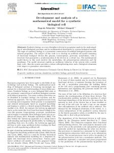
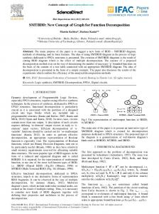
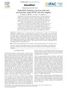
OLTCs are utilized to tackle significant voltage variations caused by large wind fluctuations. The optimal control schedule of OLTCs are obtained by MPC. Fig. 1 shows the principle of MPC. At time instant k, based on current states and system model, the future output behaviors (from k to k + Np ) of all allowable control sequences (from k to k + Nc ) are predicted via simulation, where Nc ≤ Np . According to the predicted outputs and cost functions, the performance of each candidate control sequence is calculated. The optimal sequence is selected, but only its first element is implemented at the current interval [k, k + 1]. The whole process is repeated at next time instant k+1.
(1) Besides the aforementioned different action time scales, the voltage regulating characteristics between OLTCs and STATCOMs are also different. Compared with continuous adjustments of STATCOMs, the voltage adjustments of OLTCs are discrete and
The above principle is applied to design control schedule for OLTCs. The control variables are tap changer operations of OLTCs. Only one single step is allowed at each time for each OLTC: T ∆u(k) = [∆n1 (k), ∆n2 (k), ..., ∆nM (k)] (1) 2
IFAC CPES 2015 December 9-11, 2015. Delhi, India
Zhiyuan Tang et al. / IFAC-PapersOnLine 48-30 (2015) 001–006
∆ux is regarded to dominate ∆uy if the following inequalities are satisfied: { Ji (∆ux ) ≤ Ji (∆uy ), ∀i ∈ {1, 2}, (5) Jj (∆ux ) < Jj (∆uy ), ∃j ∈ {1, 2}
If one solution can not be dominated by any other feasible solutions, then it is regarded as a non-dominated one, which constitutes the whole Pareto front. For the whole procedure of the computation, refer to Ma et al. (2008).
In the set of Pareto front, each Pareto solution has its own unique contribution to these two tradeoff objectives. The operators can choose an optimal solution according to control preferences and practical needs from the obtained Pareto front by setting different weights for the two objectives: J(∆u⋆i ) = αJ1 (∆u⋆i ) + βJ2 (∆u⋆i ) (6) ⋆ where ∆ui is one Parato solution; α and β are the positive weights of two objectives; Pareto solution with minimal J is selected as the optimal solution.
Fig. 1. Principle of model predictive control where T denotes transposition of a vector, k is the discrete time instant, M is the total number of OLTCs in the network, ∆nj (k) is the tap change of the j th OLTC (denoted by OLT Cj for simplicity in the rest of the paper) at time k, and vector ∆u(k) represents the collected tap change actions of OLTCs at time k.
In this paper, α and β are designed so that the optimal solution is the one with the least number of operation frequency, which can extend lifetime of OLTCs. 2.2 Control Scheme of STATCOMs
The future output behaviors are obtained by power system simulation with a predicted wind power profile and assessed by the two objectives: ∑∑ J1 = min ∆nj (k) j
J2 = min
k
∑∑ i
subject to:
3
nmin ≤ n0j + j
k
|vi (k) − vref | + ε
∑ k
∆nj (k) ≤ nmax j
STATCOMs are applied to handle voltage violations of the critical bus caused by small wind fluctuations. As mentioned above, we regard voltage violation of the critical bus as an event. Once the violation happens, the critical bus will send event information to a selected STATCOM and the corresponding consensus based distributed controller is activated immediately. The event information is the voltage violation of critical bus: { Vc,max − Vc,mea , Vc,mea > Vc,max , ∆Vc = (7) Vc,mea − Vc,min , Vc,mea < Vc,min where Vc,mea is the measured voltage of critical bus, Vc,max and Vc,min are the upper and lower voltage limit of the critical bus, respectively.
(2)
(3)
∆nj ∈ {∆Tj , −∆Tj , 0}
(4) Vmin ≤ vi (k + i | k) ≤ Vmax for i = 0, 1, ..., Np . Here J1 , and J2 are objectives aiming at minimizing voltage deviation, and operation frequency of OLTCs; vi (k) is the voltage magnitude of bus i at time k; vi,ref denotes the voltage reference value of bus i which is the original bus voltage before a large wind fluctuation occurs; ε is added as a punishment when vi (k) falls outside the voltage variation range [Vmin , Vmax ]; n0j is the initial and nmax represent the lower position of the OLT Cj ; nmin j j and upper tap position limits of the OLT Cj , respectively; ∆Tj is one moving step size of the OLT Cj .
The relation between the voltage violation of the critical bus and reactive power changes of STATCOMs is: ∆Vc = Sc,1 ∆Q1 + Sc,2 ∆Q2 + . . . + Sc,N ∆QN (8) where N is the number of STATCOMs in the network; Sc,i is the sensitivity value of reactive power of the ST AT COMi to voltage of the critical bus, which can be calculated through power flow Jacobian (Baghsorkhi and Hiskens (2012a)); ∆Qi is the reactive power change needed for the ST AT COMi . To minimize the maximal capacity of STATCOMs, the reactive power required should be shared equally. Therefore, according to (8), the final reactive power change for each STATCOM should be: ∆Vc ∆Q = ∑N (9) i=1 Sc,i
To solve a two-objective optimization problem can be quite time-consuming, in particular when the problem has a large number of variables, which is the key limit for on-line application. Under the assumption that large wind power variation can be predicted accurately, the Pareto front of the two-objective optimization problem can be obtained in advance by using predicted wind power.
It is assumed that each STATCOM only knows its own sensitivity value and only the selected STATCOM get the event information ∆Vc . To realize (9), each STATCOM ∑N should get the global information (∆Vc and i=1 Sc,i ) after information exchange. Consensus algorithms have
The idea of non-dominated solutions is applied to form the Pareto front of this two-objective optimization problem. Let us suppose that ∆ux and ∆uy are any two different feasible solutions of the above two-objective problems. 3
IFAC CPES 2015 4 December 9-11, 2015. Delhi, India
Zhiyuan Tang et al. / IFAC-PapersOnLine 48-30 (2015) 001–006
been used in distributed control for various purposes (see Xu et al. (2011) and Mokhtari et al. (2013) for examples). The key idea of a consensus algorithm is to make states of agents with different initial conditions converge to a common value after information exchange. In the following, we will use a consensus algorithm to discover this global information.
The information discovery process can be expressed as: N ∑ k xk+1 = x + aij (xkj − xki ) (10) i i
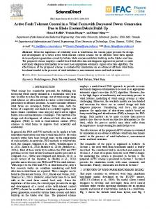
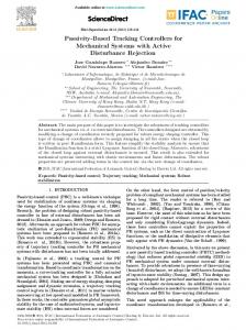
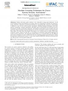
Fig. 2. Communication structure of the proposed distributed control technique
Let an undirected connected graph G = {V, E} describe the communication structure among STATCOMs, where V represents the set of nodes, and E ⊆ V × V represents the set of edges. Each node represents one STATCOM and the edge (i, j) denotes ST AT COMi and ST AT COMj can obtain information from each other. And aij satisfies the following two conditions: N ∑ aij = aji , aij = 1 (11)
STATCOMs can not figure out the reactive power change needed based on information in (16) for lacking information of r. Therefore, a new flag element is added to represent the information of number of selected STATCOMs: { 1, i ∈ R, f lagi = (17) 0, i ̸∈ R
can only communicate with its adjacent STATCOMs, bidirectionally (communication delay is not considered in this paper). If we use the same initial information vector for each STATCOM, then the final information vector will become: N r∆Vc 1 ∑ �i = [ x , Sc,i ] (16) N N i=1
j=1
where xki and xkj represent the information vectors discovered by the ST AT COMi and ST AT COMj at k th information exchange, respectively; aij is the coefficient of information exchange between ST AT COMi and ST AT COMj .
In this way, after information exchange, all the nodes get the same information: r f� lag i = , N N 1∑ S�c,i = Sc,i , (18) N i=0 r∆Vc ∆V� = c,i N And the required reactive power change for each STATCOM can be calculated: ∆Vc ∆V�c,i ∆Q = ∑N = (19) Sc,i lag N S�c,i f�
j=1
{
aij = 0, 0 < aij < 1,
i ̸= j, (i, j) ̸∈ E, otherwise
(12)
According to the consensus algorithm, the ultimate information discovered by each STATCOM is N 1 ∑ 0 �i = x (13) x N i=1 i
�i is the where x0i is the initial information vector and x final information vector of each node.
i=1
i
Remark: Centralised and decentralised control schemes have been applied to control voltages. However, centralised control requires global information from all the nodes and lacks scalability and reliability (one point failure). Decentralised control has high stress on voltage control devices and lacks coordination. Distributed control has been proposed here to tackle drawbacks of centralised and decentralised control.
The initial information vector consists of two elements T x0i = [∆Vc,i , Sc,i ] . The definition of ∆Vc,i is as follows: { ∆Vc , i ∈ R, ∆Vc,i = (14) 0, i ̸∈ R
where R = {i} is the index set of nodes receiving event information. After information exchange, the final information vector of each node becomes: N ∆Vc 1 ∑ �i = [ , x Sc,i ] (15) N N i=1
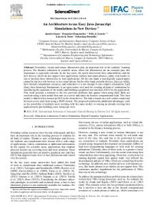
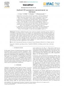
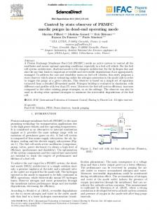
3. TEST SYSTEM In this paper, a modified IEEE 14-bus system is used as a test system, which is shown in Fig. 3.
Based on information in (15), each STATCOM can calculate the required reactive power change accordingly (the first element divided by second element).
Two wind farms are added to buses 13 and 14 of the original network, each of which has a STATCOM at POI. For simplicity, only two OLTCs are considered in the network, which divide the network into two regions: region 1 (regarded as a weak sub-transmission system) and region 2 (regarded as a transmission system). To enlarge the voltage effects of wind power fluctuation, we adjust the line resistance ratio of region 1 to be approximately equal one. The total load is 352.17 MW and 110.46 MVar, of which the total active load of region 1 is 112.35 MW. The
However, if the communication link between the selected STATCOM and critical bus fails, the whole consensus based distributed control will not be activated. To improve robustness of the proposed distributed control method, we can send ∆Vc to several selected STATCOMs. Let us assume that there are r selected STATCOMs, where 2 ≤ r ≤ N . Fig. 2 shows the communication structure of the modified method. Again, each STATCOM 4
IFAC CPES 2015 December 9-11, 2015. Delhi, India
Zhiyuan Tang et al. / IFAC-PapersOnLine 48-30 (2015) 001–006
voltages of the sub-transmission network are regulated within the range 0.965 ∼ 1.065 p.u.. The voltage threshold of the critical bus is 1.015 ∼ 1.025 p.u..
The effectiveness of our proposed approach is proved in case 1. The advantages of our proposed control scheme are shown by comparing control costs with a practical control approach conducted in case 2.
4.1 Case 1
In MPC, the sample time period is chosen as one minute, which is close to the action time scale of OLTCs. The controller uses Nc = Np = 3. The Voltage range [Vmin , Vmax ] is set as [0.98, 1.05] p.u..
During the simulation, the OLTCs act at the corresponding time according to the best control sequence. Table 1 shows the effective optimal control sequence in 90 minutes, where 1/-1 mean the tap of the corresponding OLTC is increased/decreased respectively by one single step; 0 means there is no action for the corresponding OLTC. Only the time sequence when at least one OLTC takes action is shown in the table. When the voltage of the critical bus violates the threshold, event-triggered distributed control will take action at once. Table 1. Best control sequence of the OLTCs
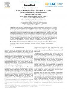
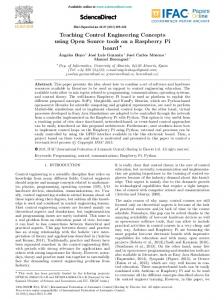
Fig. 3. The modified IEEE 14-bus test system basic power is 100 MVA. All loads are considered constant during simulation. The capacity of wind farm 1 and farm 2 are 32 MW and 22 MW, respectively. Fig. 4 shows a 1.5 hour-long minute-byminute wind generation profile for a site in China, which is used for testing. The predicted data used is the average value before each large wind fluctuation (change of wind power exceeds 0.2 p.u.) occurs. The absolute wind power prediction error is less than 10% p.u. of the corresponding nominal capacity of wind farm. And it is assumed that there is 100% correlation between the two wind farms.
Time(min) OLTC1 Control Action OLTC2
1.024
Voltage (pu)
predicted wind power real wind powr
46 1 0
48 1 1
49 1 0
upper limit
Case 1
Case 2
1.022 1.02 1.018
1.014
0.8
Power (pu)
45 -1 1
1.016
1
lower limit 10
20
30
40
50
Time (min)
60
70
80
90
Fig. 5. The voltage variation of the critical bus (bus 11)
0.7
As shown in Fig. (5) and Fig. (6), the proposed control strategy achieves the voltage control goals (solid lines).
0.6 0.5
4.2 Case 2
0.4 0.3
9 0 -1
1.026
Through sensitivity analysis, we find that the sensitivity values of voltage at bus 11 to wind injection at wind farms 1 and 2 are very close to the average sensitivity level of region 1, which means voltage change at bus 11 can represent the voltage fluctuation of the whole region 1. Thus, unregulated bus 11 is selected as the critical bus.
0.9
5
20
40
Time (min)
60
One practical voltage control approach is applied in this case: the voltages of POIs are regulated to fixed setting values by corresponding STATCOMs. This leaves only the traditional voltage control by OLTCs. The setting values of wind farms 1 and 2 are 1.05 p.u. and 1.04 p.u., respectively. The voltages of bus 7 and 6 are controlled by OLTCs 1 and 2 with dead band width 0.01 p.u., respectively.
80
Fig. 4. 90-min wind power profile (p.u. of nominal capacity) 4. CASE STUDY
Although the practical control approach can realize the aforementioned voltage control objectives (dashed lines in Fig. (5) and Fig. (6)), there is no coordination between
Usually, the voltage fluctuation range of POIs is −10% ∼ 10% around the nominal voltage. In this work, all bus 5
IFAC CPES 2015 6 December 9-11, 2015. Delhi, India
Zhiyuan Tang et al. / IFAC-PapersOnLine 48-30 (2015) 001–006
5. CONCLUSIONS
STATCOMs and OLTCs. As a result, the highly strict voltage regulation of POIs makes the operation frequency of OLTCs become unexpected high. Also, the required reactive power capacity of STATCOMs is much larger than that of our proposed control strategy (the maximum of absolute reactive power in case 1 is 0.017 p.u. (1.7 MVar) while that in case 2 is 0.0598 (5.98 MVar)). In all, through comparison with case 2, our proposed control scheme have three significant advantages:
Voltage violations at POIs and voltage fluctuations at unregulated load buses are the two main negative impacts of wind power variability on sub-transmission networks. In this paper, both voltage issues are handled in a novel coordinated way. The main idea is to regard wind power fluctuations as the combination of large and small wind variations whose voltage impacts are handled by OLTCs and STATCOMs, respectively. Through the coordination of both control objectives, OLTCs and STATCOMs are full utilized based on their own control characteristics. In addition, a flexible control of OLTCs is realized by solving a two-objective optimization problem in MPC, and STATCOMs are controlled in a robust distributed manner. The effectiveness of our proposed control method is substantiated in a modified IEEE 14-bus system with a real wind power profile. The advantages of our proposed control scheme are shown through comparing control cost with one existing control strategy.
(1) The operators can choose different control strategies according to their preferences. (2) The number of tap change operations of two OLTCs is reduced from 14 to 7, which can extend the lifetime of OLTCs significantly; (3) The maximal required capacity of STATCOMs is decreased to about 28% of that needed in case 2, shown in Fig. 7. 1.06
Voltage (pu)
1.04
REFERENCES
maximal voltage in Case 1 minimal voltage in Case 1 maximal voltage in Case 2 minimal voltage in Case 2 1.065 p.u. 0.965 p.u.
1.02
Baghsorkhi, S.S. and Hiskens, I.A. (2012a). Analysis tools for assessing the impact of wind power on weak grids. Systems Conference (SysCon), IEEE International, 1–8. Baghsorkhi, S.S. and Hiskens, I.A. (2012b). Impact of wind power variability on sub-transmission networks. Power and Energy Society General Meeting, IEEE, 1–7. Carvalho, P.M., Correia, P.F., and Ferreira, L.A. (2008). Distributed reactive power generation control for voltage rise mitigation in distribution networks. Power Systems, IEEE transactions on, 23(2), 766–772. Li, Y., Hill, D.J., and Wu, T. (2004). Optimal coordinated voltage control of power systems–an immune algorithm solution. Control Conference, 5th Asian, 3, 1398–1403. Ma, H. and Hill, D.J. (2014). Adaptive coordinated voltage control–Part I: Basic scheme. Power Systems, IEEE Transactions on, 29(4), 1546–1553. Ma, H., Ng, K.T., and Man, K.F. (2008). Multiobjective coordinated power voltage control using jumping genes paradigm. Industrial Electronics, IEEE Transactions on, 55(11), 4075–4084. Mokhtari, G., Ghosh, A., Nourbakhsh, G., and Ledwich, G. (2013). Smart robust resources control in LV network to deal with voltage rise issue. Sustainable Energy, IEEE Transactions on, 4(4), 1043–1050. Robbins, B.A., Hadjicostis, C.N., and Dom´ınguez-Garc´ıa, A.D. (2013). A two-stage distributed architecture for voltage control in power distribution systems. Power Systems, IEEE Transactions on, 28(2), 1470–1482. Valverde, G. and Van Cutsem, T. (2013). Model predictive control of voltages in active distribution networks. Smart Grid, IEEE Transactions on, 4(4), 2152–2161. Xu, Y., Liu, W., and Gong, J. (2011). Stable multi-agentbased load shedding algorithm for power systems. Power Systems, IEEE Transactions on, 26(4), 2006–2014. Zong, Y., Kullmann, D., Thavlov, A., Gehrke, O., and Bindner, H.W. (2012). Application of model predictive control for active load management in a distributed power system with high wind penetration. Smart Grid, IEEE Transactions On, 3(2), 1055–1062.
1 0.98 0.96
10
20
30
40 50 Time (min)
60
70
80
90
Fig. 6. Maximal and minimal voltage evolutions in two cases
Reactive Power (pu)
0.1
STATCOM STATCOM STATCOM STATCOM
0.05
1, 2, 1, 2,
Case Case Case Case
1 1 2 2
0
−0.05
−0.1
10
20
30
40
50
Time (min)
60
70
80
90
Fig. 7. Reactive power changes of the STATCOMs in two cases (p.u. of 100MVA) Remark: In Fig. 6, due to the relaxation of local control conditions of POIs, the maximum and minimum voltages in case 1 are closer to the voltage limits than case 2. Besides, the maximum voltage in case 2 is the voltage of bus 14 (the POI of Wind Farm 1) which is constant through dynamic control of Statcom 1. In Fig. 7, since the reactive power changes of statcoms 1 and 2 in case 1 are the same, the two corresponding curves are exactly the same. 6