1972
IEEE TRANSACTIONS ON NUCLEAR SCIENCE, VOL. 62, NO. 5, OCTOBER 2015
Scintillation Detector Timing Resolution; A Study by Ray Tracing Software David N. ter Weele, Dennis R. Schaart, Senior Member, IEEE, and Pieter Dorenbos
Abstract—Time-of-flight positron emission tomography requires high timing resolution. In this paper, we determined the influence of scintillation properties on the detector timing resolution for crystals with non-negligible optical transit timespread. In addition to intrinsic scintillation properties, such as the light yield, decay time constant, and scintillation rise time, we also studied the relation between the timing resolution and extrinsic scintillation properties, such as the dimensions of the crystal, the absorption probability of the reflector, the dwell time of photons inside the reflector during the reflection process, and the crystal polish. For this purpose, we developed ray-tracing software. The crystals simulated in this paper are LSO:Ce, LYSO:Ce, LSO:Ce,0.2%Ca, LYSO:0.11%Ce,0.2%Mg, and LYSO:0.2%Ce,0.2%Ca, with dimensions mm , mm , mm , mm . We furthermore studied the optical transit and timespread of photons inside polished and etched crystals, which explains the differences in timing resolution. Index Terms—Absorption probability, crystal polish, decay time constant, dwell time, light yield, optical transit time-spread, raytracing software, scintillation rise time, simulation, timing resolution.
I. INTRODUCTION
T
IME-OF-FLIGHT positron emission tomography (TOF-PET) can significantly increase the signal-to-noise ratio (SNR) compared to conventional PET [1]–[5]. This requires excellent timing resolution. The scintillator plays an important role in the timing uncertainty of a scintillation detector. and (LSO:Ce) are commonly used in (TOF-)PET systems. For excellent timing, the scintillator must offer a high light yield, a short decay time constant, and a short scintillation rise time [6]. The relation between these intrinsic scintillation properties and the detector timing resolution has been studied before and published in [7]. The timing uncertainty appears to be proportional to the square root of the decay time divided by the light yield. This, however, is only valid for small crystals (i.e., mm ). In crystals with non-negligibly small dimensions, additional timespreads arise. First, gamma photons are absorbed at
Manuscript received April 07, 2015; revised June 24, 2015; accepted July 15, 2015. Date of publication September 23, 2015; date of current version October 09, 2015. This work was supported in part by EU FP7 project SUBLIMA under Grant Agreement 241711, see also www.sublima-pet-mr.eu. The authors are with Delft University of Technology, Delft 2629 JB, Netherlands (e-mail:
[email protected];
[email protected];
[email protected]). Color versions of one or more of the figures in this paper are available online at http://ieeexplore.ieee.org. Digital Object Identifier 10.1109/TNS.2015.2460266
different positions in the bulk of the crystal, which contributes to the total timing uncertainty. Second, the light collection efficiency depends on the absorption position of the gamma photon. In other words, the timing resolution depends on the gamma absorption distribution inside the crystal. Third, the traveling path from the ionization track to the photon detector varies from photon to photon. This timespread distribution is known as the photon timespread distribution in [8] and as the optical transit timespread in [9] and in this paper. In [8] and [9], it was shown that broadens with the dimensions of the crystal and that it depends on the crystal surface polish, and on the reflection properties of the packaging. It was furthermore shown in [8] and [9] that photons can travel a few picoseconds inside Teflon tape during the reflection process, referred to as the dwell time, which broadens . It is expected that this phenomenon worsens the timing resolution. Ray-tracing software is a powerful tool to attain information about optical transit timespreads. GATE, GEANT4, and Litrani are codes that are often used to study and its effect on the detector timing resolution [10]–[13]. Using these Monte Carlobased software packages, it cannot be studied how the dwell time of photons within the reflecting material affects and the timing resolution. We developed a Monte Carlo-based ray-tracing software package that allows us to take into account that dwell time. In this paper, we determined, by means of ray-tracing software, the relation between the timing resolution and the intrinsic and extrinsic scintillation properties. We considered a crystal coupled to a photon detector that creates a time stamp for each detected photon. The path, including all internal reflections and dwell time within reflecting material, of each scintillation photon created in a gamma detection event was traced. After simulating 2000 gamma events, we determined the full-width half maximum (FWHM) in the time stamp distribution of the th detected scintillation photon, for each in the range 1 to 100. The smallest among them is defined as , and provides a measure for the obtainable timing resolution. The parameter was simulated for the following scintillation materials: LSO:Ce, LYSO:Ce, LSO:Ce,0.2%Ca, LYSO:0.11%Ce,0.2%Mg, and LYSO:0.2%Ce,0.2%Ca. The dimensions of the crystal were chosen as infinitely small: mm , mm , mm , and mm . The of the different scintillation materials was compared for all crystals dimensions. The simulation was performed for crystals with all faces polished and for crystals with five faces etched crystals and the remaining face polished. To understand the differences in , we also determined .
0018-9499 © 2015 IEEE. Personal use is permitted, but republication/redistribution requires IEEE permission. See http://www.ieee.org/publications_standards/publications/rights/index.html for more information.
TER WEELE et al.: SCINTILLATION DETECTOR TIMING RESOLUTION
1973
TABLE I INTRINSIC SCINTILLATION PULSE-SHAPE PARAMETERS AND THE NUMBER OF SIMULATED SCINTILLATION PHOTONS PER GAMMA EVENT
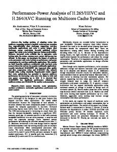
Fig. 1. Incoming gamma photon creates an ionization track in a scintillator packed on five of its surfaces in Teflon tape and coupled with a polished surface to a photon detector.
We furthermore studied the importance of the properties of the reflector. , defined as the probability that a scintillation photon will be absorbed by or will pass through the reflector when it hits the crystal reflector interface, varied from 0 to 0.05 and the dwell time of photons inside the reflector varied between 0 and 5 ps. We finally tested how the light yield, decay time constant, and intrinsic rise time of the scintillation pulse affect the timing resolution for different crystal dimensions. II. METHODS A. Timing Resolution Fig. 1 shows an incoming gamma photon creating an ionization track inside a scintillator where a polished surface is always coupled to a photon detector. From the ionization track, the photons of the intrinsic scintillation pulse are emitted isotropically. The shape of is determined by processes inside the ionization track, for example, by an energy transfer of the electron-hole pairs, by quenching mechanisms, and by radiative and nonradiative decay processes of excited luminescence centers [14]. The intensity and shape of the light arriving at the photon detector differs from , as the traveling path of scintillation photons from the ionization track to the photon detector varies from photon to photon. It is furthermore spread out in time by the photon detector due to the detector transit timespread, denoted as . Hence, the observed pulse shape is the convolution between and the timespreads and as given (1) is the An often-used measure for the timing resolution slope of the rising edge of . In the hypothetical case where all gamma photons are absorbed at the same positon inside the crystal (which can be considered as nonhypothetical for crystals smaller than mm ), is given by (2) [6], [7] (2) is the light yield and is the decay time constant. where The first reason why (2) cannot be applied directly to crystals of dimensions larger than mm is that depends on the position of absorption of the gamma photon and, therefore, the slope varies for each absorbed gamma photon. This
1 Agile Technologies 2 Crystal Photonics GmbH 3 Saint-Gobain Crystals
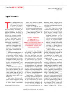
results in additional timing uncertainty, just like the variation in traveling times of the gamma photons inside the crystal. In [9], the shape of was determined by means of the experiment as well as by ray-tracing software. In addition, an analytical model was introduced that explains the observed exponential decay. A typical value for the decay constant of is hundreds of picoseconds for five sides etched and all sides polished crystals that are mm to mm in size. In case of silicon photomultipliers, can often be described by a Gaussian function with a full width at half maximum (FWHM) of no more than 300 ps [7]. B. Ray-Tracing Software In the simulations in this paper, we consider co-doped and non co-doped LSO:Ce and LYSO:Ce crystals with properties as shown in Table I. The crystals are directly coupled to a photon detector, that is, without any optical coupling material in between. The photon detector creates a time stamp for every detected scintillation photon. The time-stamp distribution is then essentially equal to . The simulation software we developed was introduced in [9]. Initially, it was used to study . The software has been developed further to study timing resolution. Fig. 2 shows a cuboid crystal with dimensions , , and . To obtain the timing resolution or a good measure thereof, we simulated the situation in which gamma photons travel in the -direction and enter the crystal through a random position at the ( )-plane at 0 at 0 s. The crystal side that is attached to the photon detector is referred to as the exit surface of the crystal. The depth ( -coordinate) at which the gamma photon creates an ionization track within the scintillator is determined from the probability density function , where is the attenuation length of L(Y)SO:Ce for gamma absorption at 511 keV and assumed to be 1.14 cm [15]. Furthermore, is defined as the traveling time of the gamma photon inside the crystal and calculated by dividing the depth of interaction by the speed of light in vacuum. The ionization track is considered to be infinitely short. Thus, the photons of the scintillation pulse are emitted isotropically from the interaction position. In [16],
1974
IEEE TRANSACTIONS ON NUCLEAR SCIENCE, VOL. 62, NO. 5, OCTOBER 2015
Fig. 2. Cuboid-shaped crystal with dimensions , , and , as used by the ray-tracing software. Gamma photons enter the crystal from the left-hand side, whereas the right-hand side is coupled to a photon detector.
was experimentally determined for all scintillation materials listed in Table I, using 100 ps (FWHM) x-ray excitation ( keV). All scintillation pulse shapes could be described in the following equation:
(3) Each shape consists of a single scintillation rise time of 90 ps and a slow and fast decay time constant [16]. The slow and fast decay components contain a fraction and of the total intensity, respectively. The values are given in Table I. Since it is a Monte Carlo-based code, the traces of a single emitted scintillation photon are simulated, and each detected scintillation photon creates a time stamp. The time of emission is determined from (3), which, similar to (1), is a probability density function. Since the photon detection efficiency of the photon detector is smaller than 1, it is inefficient to trace all emitted scintillation photons. In [7], a photoelectron yield of 4700 was measured from an etched LYSO:Ce crystal mm in size coupled to a silicon photomultiplier using 511-keV gamma excitation. The number of simulated scintillation photons per gamma excitation was determined by dividing the photoelectron yield by the light collection efficiency. It will be shown in section 3.3 that the light collection efficiency for this crystal is 0.82, thus 5730. The actual light yield is divided by the photon detection efficiency of the photon detector. In [16], the photoelectron yields of all scintillation materials were measured relative to LYSO:Ce from which we determined for each material, given by the second column in Table I. The optical transit time is the traveling time of the scintillation photon inside the crystal and is calculated by , where is the total traveling distance inside the crystal and the refractive index , while is the speed of light in the vacuum. In all simulations, either Lambertian-Beer or specular reflection was assumed at the crystal surfaces. In this paper, it is referred to as etched and polished crystals, respectively. For etched as well as polished crystals, the exit surface is always polished. When a photon hits one of the five wrapped crystal surfaces, there is a probability of losing the photon, that is, the reflector absorbs the photon or the photon passes through the reflector. In case of Lambertian-Beer reflection, the angle of reflection is independent of the angle of incidence . In case of specular reflection . In practice, it is unlikely for a
photon to reflect specularly if it has dwelled inside the reflector, for example, in Teflon tape. Since we wish to study two extreme cases, in our simulations for polished crystals, photons always undergo specular reflection. This means that we do not distinguish photons that reflect at the crystal surface and photons that dwell inside the reflector before they re-enter the crystal. Since the exit surface is polished, photons can only be detected if the angle of incidence is smaller than the critical angle , calculated by (4) is the refractive index of the crystal and is the where refractive index of the entrance window of the photon detector. Assuming 1.82, for (air) and for . The latter was assumed to be the refractive index of the entrance window of the photon detector. If , there is a probability that the scintillation photon undergoes specular reflection. is given by (5) , for and for . If , photons undergo specular reflection. For polished perfect cuboid-shaped crystals, a part of the photons will be trapped inside the crystal due to total internal reflection. Those trapped photons do not create a time stamp. In our simulations, a dwell time is added to the time stamp for each reflection at the crystal reflector interface. The total number of reflections times the dwell time is denoted by . The detector transit time is the time between the creation of a photoelectron in the photon detector and the time stamp. is determined from a Gaussian distributed probability density function with a standard deviation 50 ps, which is a typical value for SiPMs. Hence, the timestamp is given by (6) and is equal to the summation of all individual contributions. was obtained by creating a histogram of all time stamps, with a bin width of 1 ps If
(6) Thus, the time stamp of a scintillation photon is equal to the summation of the traveling time of the gamma photon inside the crystal, the time between excitation, and the emission of the scintillation photon, the traveling time of the scintillation photon inside the crystal, the total dwell time of all reflections, and the detector transit time. For each gamma event, the paths of scintillation photons are traced. The number of detected photons varies per gamma event if . The obtained time stamps are subsequently ordered in time. The number of simulated gamma events is chosen to be 2000 for all simulations. In this paper, the FWHM of the distribution in the 2000 time stamps of the first detected photon is defined as (1). It has been shown that triggering on the first detected photon does not necessarily result in the best [7]. Therefore, we determined for the first detected photon ( ) until the 100th detected photon ( 100). The smallest ( ) is defined as
TER WEELE et al.: SCINTILLATION DETECTOR TIMING RESOLUTION
and provides our measure, or figure of merit, for the best timing resolution obtainable. C. Simulations In order to test the simulation software, we first considered an infinitely small LYSO:Ce crystal and, therefore, 0, 0, and 0, while the light collection efficiency is equal to 1. This results in a photoelectron yield of 5730. Seifert et al. introduced an analytical method [7] to calculate from a given and photoelectron yield. The method is entirely based on statistical mathematics, and was performed for . The mathematical results will be compared with the results obtained by our ray-tracing software. For crystals of larger dimensions, varies for each gamma event and the model in [7] does not apply. Unless indicated otherwise, the settings of the simulations are as follows. is described by the scintillation pulse shape of LSO:Ce,0.2%Ca in Table I. It was shown in [16] that this material shows the best timing performance among the scintillation materials used in this paper. The number of simulated scintillation photons 5750. The remaining settings are 0.02 and 1.5. For each reflection at the crystal reflector interface 1-ps dwell time was added to . The relation between and the dimensions of the crystal, surface polish, and was investigated. was determined for both five sides etched and all sides polished crystals of mm , mm , mm , and mm in size, and for a mm crystal with double-sided readout. In this case, two photon detectors are coupled to opposite crystal sides, that is, 0 and . The time stamps from both detectors are combined. This means that the two lists of time stamps are merged, then time-ordered as a single list. varied between 0 to 0.05. To explain the differences in , the optical transit timespread was determined as well and we studied how many times the first 100 detected photons reflect, on average, at the crystal reflector interface. In all simulations so far, gamma photons entered the crystal through the ( , )-plane at 0, referred to as head-on irradiation. We also study if side irradiation, that is, through the ( , )-plane at , results in better timing resolution. This was performed for all crystals listed in Table II. The results are compared to the results measured with side irradiation in [17]. We furthermore studied the influence of on and how much improves in case of perfect coupling between the crystal and photon detector, that is, for 1.82. In [16], it was shown that is 19% worse for standard LSO:Ce compared to LSO:Ce,0.2%Ca. This, however, only applies for crystals with no optical transit timespread. Typical crystal dimensions in (TOF-)PET-systems are mm . We determined the relative timing resolution of all scintillation materials compared to LSO:Ce,0.2%Ca for crystals mm , mm , mm , and mm in size. For all crystal dimensions, the relation between and the light yield, decay time constant, and scintillation rise time was studied by improving these intrinsic scintillation properties by a factor of 0.5, 2, or 4.
1975
TABLE II TIMING RESOLUTION OF ETCHED AND POLISHED LSO:CE,0.2%CA CRYSTALS FOR DIFFERENT CRYSTAL GEOMETRIES AS A FUNCTION OF THE ABSORPTION PROBABILITY. THE CRYSTALS WERE IRRADIATED FROM THE FRONT (HEAD-IRRADIATION). THE LIGHT COLLECTION EFFICIENCY IS GIVEN WITHIN BRACKETS
D stands for double-sided readout.
Finally, it was studied whether the dwell time inside a reflector can significantly affect . The dwell time was chosen as 0, 1, 2, 3, and 5 ps for etched crystals with dimensions of mm and mm . III. RESULTS AND DISCUSSION A. Intrinsic Timing Resolution The timing resolution of an infinitely small LYSO:Ce crystal coupled to a photon detector with a detector transit timespread of 50 ps was determined, the result of which we will refer to as the intrinsic timing resolution. In this case, the photoelectron yield equals , 0, 0, and 0. Therefore, the dwell time and are not applicable. From the photoelectron yield (5730) and the probability density function , given by (1), where is a delta pulse, the was determined in two different approaches. The red curve in Fig. 3 was determined by means of statistical mathematics using the model introduced by Seifert et al. [7]. The black curve was obtained by creating 2000 gamma interaction events, each creating 5730 time stamps from the probability density function , using a random number generator. for was determined. Since each gamma event results in the same number of time stamps, the energy resolution was assumed to be 0%. Both approaches show the same result. Triggering on the first detected photon results in a timing uncertainty of 79 ps, whereas triggering on the 8th detected photon results in 56 ps. In the remainder of this paper, we determined from all simulations. is a good measure for the timing resolution since it is also proportional to the square root of the decay time divided by the light yield [7].
1976
Fig. 3. Intrinsic timing resolution
IEEE TRANSACTIONS ON NUCLEAR SCIENCE, VOL. 62, NO. 5, OCTOBER 2015
Fig. 4. Optical transit timespread of etched and polished crystals and mm in size.
of LYSO:Ce.
B. Polished Versus Etched Crystals It was shown in Fig. 3 that the simulation software is in excellent agreement with the analytical timing model in [7] for infinitely small crystals. In this section, we use the simulation software to find for larger crystals with non-negligible optical transit timespread. Table II shows for etched and polished LSO:Ce,0.2%Ca crystals of dimensions mm , mm , mm , and mm , coupled to a photon detector. varied between 0 and 0.05. The dwell time was chosen 1 ps. The light collection efficiency is given within brackets. An etched crystal mm in size shows a smaller than a polished crystal of the same dimensions, viz. 86 ps compared to 91 ps. For crystal dimensions mm , polished crystal surfaces are desired. is 116 ps and 265 ps for polished and etched crystals, respectively. The light collection efficiency of etched crystals drops significantly by increasing the dimensions of the crystal. For 0.02, the light collection efficiency of an etched crystal decreases from 0.82 to 0.45 by increasing the dimensions of the crystal from mm to mm . For a polished crystal, the light collection efficiency only decreases from 0.41 to 0.38. The twice-as-low light collection efficiency for polished crystals mm in size compared to an etched crystal of equal dimensions is explained by scintillation photon trapping in perfect cuboid-shaped polished crystals, due to total internal reflection. Trapped photons do not create a time stamp. Only photons emitted under an angle smaller than (of ) with respect to the -axis (see Fig. 2) are able to enter the detector. The fraction of photons that creates a time stamp (if 0) is denoted as and is calculated as follows: (7) It follows that 0.43. Photons emitted under an angle larger than with respect to the -axis do not create a time stamp. In practice, those photons will not be trapped forever due to imperfections of the crystal surface and nonperfect cuboid shape and may create a time stamp at a later time. For timing, those photons can be considered as lost, as they travel significantly longer than the nontrapped photons, depending on the quality of the crystal.
mm
Recall that the timing resolution is determined by the slope of the rising edge of . This slope is proportional to the light collection efficiency, but it is also affected by . The latter depends on the dimensions of the crystal, surface polish, and . Fig. 4 shows for etched and polished crystals mm and mm in size. As shown by experiment and simulation in [9], shows a rising part followed by an exponential decay. For high timing resolution, the decay constant of is desired to be small. In a polished crystal mm in size, the detected scintillation photons do not travel longer than about 160 ps, whereas they travel up to 700 ps in an etched crystal of the same dimensions. This explains why in Table II is only 10% better for etched crystals than for polished crystals, despite the twice as high light collection efficiency. For crystals mm in size and 0.02, detected scintillation photons travel up to 450 ps inside a polished crystal and up to 2.5 ns inside an etched crystal. The large difference in explains why is 2.3 times better for a polished crystal than for an etched crystal. Double-sided readout narrows and, therefore, the differences in are smaller, viz. 112 ps and 184 ps for a polished and etched crystal, respectively. The average number of times an emitted scintillation photon reflects is determined by and is the same for all emitted photons. Due to different traveling paths from the ionization track to the photon detector and due to the detector transit timespread, the first emitted photon does not necessarily create the first time stamp. If the second emitted photon has fewer reflections than the first emitted photon before being detected, it could be the first detected photon. This means that the average number of times the first detected photon reflects can be less than the average number of reflections of the remaining photons. Fig. 5 shows those average numbers for each of the first 100 detected photons. It increases with increasing , until a saturation value. For a polished and etched LSO:Ce,0.2%Ca crystal mm in size, saturation is at 2.2 and 8.4, respectively. For the first detected photon, the number of reflections is much smaller, viz. 1.5 and 1.9, respectively. The light collection efficiency improves with decreasing . This is expected to improve , as the number of detected photons increases. On the other hand, it was shown in [9] that decreasing elongates , which worsens .
TER WEELE et al.: SCINTILLATION DETECTOR TIMING RESOLUTION
1977
TABLE III TIMING RESOLUTION OF ETCHED AND POLISHED LSO:CE,0.2%CA CRYSTALS FOR DIFFERENT CRYSTAL GEOMETRIES AS A FUNCTION OF THE ABSORPTION PROBABILITY. THE CRYSTALS WERE IRRADIATED FROM THE SIDE (SIDE IRRADIATION). THE LIGHT COLLECTION EFFICIENCY IS GIVEN WITHIN BRACKETS
Fig. 5. Average number of reflections at the crystal reflector interface for the th detected photon for different crystals.
D stands for double-sided readout.
Fig. 6. Timing resolution of etched and polished LSO:Ce,0.2%Ca crystals mm in size with single- and double-sided readout as a function of the absorption probability. D stands for double-sided readout.
Table II shows that decreasing by using better reflectors always results in an improvement in , regardless of the dimensions of the crystal. All time stamps carry information, and by absorbing photons information is lost, which worsens . For an etched crystal mm in size, improves from 93 to 82 ps with decreasing from 0.05 to 0. Fig. 6 shows as a function of for crystals mm in size. The influence of on is relatively small, compared to the influence of the crystal surface polished and its dimensions. worsens from 107 to 121 ps with increasing from 0 to 0.05 for a polished crystal mm in size. For an etched crystal of the same dimensions, increases from 248 to 285 ps. The double-sided readout improves by a factor for etched crystals. For , this is fully explained by a shorter . For 0.05, the light collection efficiency increases from 0.24 to 0.54, which improves even more. For polished crystals, was found to be a few percent worse for a double-sided readout compared to a single readout, even though the light collection efficiency improves a few percent and shortens. The gamma photon absorption distribution inside the crystal decreases exponentially. In case of head-on irradiation, most of the gamma photons are absorbed in
the left-hand side of the crystal (see Fig. 2). Half of the emitted photons travel in the positive -direction and the other half in the negative -direction. In a polished crystal, both light pulses will have the same shape when arriving at the photon detector, but the light pulse traveling in the negative -direction arrives later at the photon detector at than the light pulse traveling in the positive -direction. For , the time difference is relatively small. For a double-sided readout, the time difference between the two detected light pulses is larger and, therefore, was found to be better for a single readout. In case of side irradiation, gamma photons are distributed homogeneously over the length of the crystal, where on average. For a single readout, the difference in the traveling path of the two light pulses arriving at the photon detector is then given by and in case of the double-sided readout, there is no time difference. Therefore, is expected to be better for the doubled-sided readout than for a single readout. Table III shows for the same crystals as in Table II, but this time, the crystals were irradiated from the side (i.e., through the ( , )-plane at ). For a polished crystal mm in size, is indeed better for the double-sided readout than for a single readout, viz. 101 ps compared to 137 ps. In [17], was measured for a polished crystal mm in size and found to be better for a double-sided readout than for a single readout in case of side irradiation, viz. 150 ps compared to 175 ps. Comparing Table III with Table II shows that is generally worse compared to head-on irradiation. C. Influence of the Refractive Index of the Photon Detector In this section, the influence of the refractive index of the entrance window of the photon detector on is studied,
1978
IEEE TRANSACTIONS ON NUCLEAR SCIENCE, VOL. 62, NO. 5, OCTOBER 2015
Fig. 7. Mmeasure of timing resolution as a function of the refractive index of the entrance window of the photon detector for different crystal geometries and surface finish.
Fig. 8. Fraction of emitted scintillation photons that are able to create a time stamp, as a function of the refractive index of the entrance window of the photon detector in an all-sides polished crystal.
see Fig. 1. Fig. 7 shows determined from etched and polished LSO:Ce,0.2%Ca crystals mm and mm in size. was chosen as 1.0, 1.25, 1.5, and 1.82. Increasing from 1.00 to 1.82 has a larger effect on for polished crystals than for etched crystals. For an etched crystal, improves from 105 to 85 ps and from 282 to 248 ps for crystal dimensions mm and mm , respectively. For a polished crystal, improves from 149 to 70 ps and from 175 to 108 ps for crystal dimensions mm and mm , respectively. Recall that when a scintillation photon hits the crystal surface coupled to the photon detector and , it will undergo specular reflection. was calculated as 33.3 for 1.00, 55.5 for 1.50, and 90 for 1.82. By substituting (4) in (7), one obtains as a function of , given by
TABLE IV TIMING RESOLUTION OF ETCHED AND POLISHED CRYSTALS WITH DIFFERENT DIMENSIONS. THE RELATIVE TIMING RESOLUTIONS COMPARED TO LSO:CE,0.2%CA ARE GIVEN WITHIN BRACKETS. THE DWELL TIME WAS CHOSEN AS1 ps and
(8) Fig. 8 shows where varies from 1.00 to 1.82. If 0, the number of detector photons is proportional to . With increasing from 1.00 to 1.82, increases from 0.16 to 1 and, as a result, improves. In etched crystals, all photons are able to create a time stamp, regardless of . Even for etched crystals, improves with increasing , as increases likewise, which shortens . D. Co-doped and Non Co-doped LYSO:Ce and LSO:Ce In [16], the intrinsic scintillation pulse shapes of all scintillation materials in Table I were determined. Those pulse shapes were used as an input for the simulations in this paper. Table IV shows for all scintillation materials for different crystal dimensions, viz. an infinitely small crystal (intrinsic pulse shape), an etched crystal mm in size, and a polished and etched crystal mm in size. The dwell time was chosen as 1 ps and . LSO:Ce,0.2%Ca shows the best , regardless of the crystal dimensions varying from 55 ps intrinsically to 265 ps for an etched crystal with dimensions mm . The of the scintillation materials with respect to those for LSO:Ce,0.2%Ca are given within brackets. The intrinsic
1 Agile Technologies 2 Crystal Photonics GmbH 3 Saint-Gobain Crystals
is about 22% worse for standard LSO:Ce compared to that of LSO:Ce,0.2%Ca, which is explained by its longer decay time constant, that is, 37.7 ns instead of 32.6 ns, and about 12% lower photoelectron yield. The relative differences in become smaller with increasing dimensions of the crystal, as the contribution of other timing uncertainties increases likewise, viz. the variation in and . For an etched crystal mm in size, the relative difference in between LSO:Ce and LSO:Ce,0.2%Ca has been reduced to 8%. E. Influence of Intrinsic Scintillation Properties To test the effect of light yield, decay time constant, and scintillation rise time on , simulations were performed where light was increased by a factor of and/or rise time and decay time shortened by a factor of . will be called the improvement factor and was chosen as 0.5, 2, or 4. Fig. 9 shows for etched LSO:Ce,0.2%Ca crystals mm and mm in size, as a function of the improvement factor.
TER WEELE et al.: SCINTILLATION DETECTOR TIMING RESOLUTION
1979
TABLE V TIMING RESOLUTION AS A FUNCTION OF THE TRAVELING TIME OF PHOTONS DURING THE REFLECTION PROCESS AT THE CRYSTAL REFLECTOR INTERFACE
Fig. 9. Effect of improved light yield, decay time constant, and scintillation rise time on .
In [6], it was shown that the improvement of the light yield and decay time constant follow the dotted line for infinitely small crystals which is inversely proportional to the square root of the improvement factor, like (2). For a crystal mm in size, improves from 86 to 52 ps by improving the light yield or decay time constant by a factor 4. The dotted line predicts an increase down to 43 ps. The difference is explained by the different absorption positions of the gamma photons in a larger sized crystal, which leads to variations in . In addition, the scintillation pulses are created at different positions inside the crystal and and, therefore, depends on this position. For a crystal mm in size, the improvement of the light yield and decay time constant differs even more from the dotted line. An improvement factor of 4 results in a times better . The influence of the scintillation rise time on is smaller than that of the light yield. Shortening the scintillation rise time (i.e., 90 ps) 4 times improves from 86 to 80 ps and from 273 to 241 ps for an etched LSO:Ce,0.2%Ca crystal mm and mm in size, respectively. F. Effect of Teflon Reflector Dwell Time on the Timing Resolution In [9], we demonstrated, by means of experiment, that photons can dwell more than 100 ps inside 5 layers of 0.1-mm-thick white reflecting Teflon tape until transmission through those layers takes place. Photons that are reflected by five layers of Teflon tape appear to have dwelled to no more than 1 ps inside those layers. To study the effect of the dwell time on , the dwell time was chosen as 0, 1, 2, 3, and 5 ps. was determined from an etched LSO:Ce,0.2%Ca crystal mm and mm in size. The results are given in Table V. In case of Teflon tape, the dwell time appeared less than 1 ps. For an etched mm LSO:Ce,0.2%Ca crystal, no difference in between 0 and 1 ps dwell time was observed. For the same crystal mm in size, increases from 259 to 262 ps. To be sure that this is not an uncertainty in the simulation due to a finite number of simulated gamma
events, we increased the dwell time to 5 ps. An increase of in was observed for both crystal dimensions. In conclusion, the timing resolution is barely affected by the dwell time in Teflon wrapping but it would worsen significantly if the dwell time increases up to a few picoseconds. IV. SUMMARY AND CONCLUSIONS A ray-tracing software package was developed to study the influence of intrinsic as well as extrinsic scintillation properties on the detector timing resolution for applications in (TOF-)PET. The scintillation properties for LSO:Ce, LYSO:Ce, LSO:Ce,0. 2%Ca, LYSO:0.11%Ce,0.2%Mg, and LYSO:0.2%Ce,0.2%Ca, with dimensions mm , mm , mm , and mm were used as input. The spread as FWHM in the detection of the th photon was determined from 2000 gamma interactions for 1 until 100. The smallest , denoted as , is regarded as a good measure for the best obtainable timing resolution. For etched crystals mm in size, turned out to be slightly better than for polished crystals, viz. 86 ps instead of 92 ps. For a crystal mm in size, appears 2.3 times better for a polished crystal than for an etched crystal, viz. 116 ps compared to 265 ps. The conclusion is that the etched surfaces provide better timing resolution when crystal dimensions are smaller than, say, mm and polished surfaces are preferred for larger dimensions, such as the ones used for PET applications. This result agrees with experimental findings in [17]. The influence of is the strongest for crystals with a large optical transit timespread. For an etched crystal mm in size, improves from 285 to 248 ps when decreasing from 0.05 to 0. It was furthermore shown that the optical coupling between the crystal and photon detector is more important for polished crystals than for etched crystals. Increasing the refractive index of the entrance window of the photon detector from 1.5 to 1.82, which matches the refractive index of LSO:Ce and LYSO:Ce, the fraction of photons in polished crystals that are able to create a time stamp increases from 0.43 to 1. For etched crystals , regardless of the refractive index of the entrance window of the photon detector. LSO:Ce,0.2%Ca shows the best timing performance. For infinitely small crystals, is expected to be 22% better than standard LSO:Ce, viz. 55 ps compared to 67 ps. For an
1980
IEEE TRANSACTIONS ON NUCLEAR SCIENCE, VOL. 62, NO. 5, OCTOBER 2015
etched crystal mm in size, is only 8% better for LSO:Ce,0.2%Ca than for LSO:Ce, viz. 265 ps compared to 285 ps. This is explained by additional timespreads, such as the traveling time variation of the gamma photons inside the crystal and the position-dependent optical transit timespread. Improving the light yield and decay time constant turns out to be more efficient to obtain better timing resolution than improving the scintillation rise time. For an etched crystal of dimensions, mm improves from 273 to 180 ps if the light yield increases or the decay time constant shortens by a factor 4, whereas only improves to 241 ps if the scintillation rise time shortens four times. In the quest for better scintillation materials for applications in (TOF-)PET, it appears more efficient to focus on a higher light yield and a shorter decay time constant than on a shorter intrinsic rise time.
REFERENCES [1] W. W. Moses, “Recent advances and future advances in time-of-flight PET,” Nucl. Instrum. Meth. Phys. Res. A, Accel. Spectrom. Detect. Assoc. Equip., vol. 580, pp. 919–924, 2007. [2] M. Conti, “State of the art and challenges of time-of-flight PET,” Sci. Direct Phys. Med., vol. 25, pp. 1–11, 2009. [3] M. Conti, “Focus on time-of-flight PET: The benefits of improved time resolution,” Eur. J. Nucl. Med. Mol. Imag., vol. 38, pp. 1147–1157, 2011. [4] J. S. Karp, S. Surti, M. E. Daube-Witherspoon, and G. Muehllehner, “The benefit of time-of-flight in PET imaging: Experimental and clinical results,” J. Nucl. Med., vol. 49, no. 3, pp. 462–470, 2008. [5] M. E. Daube-Witherspoon, S. Surti, A. Perkins, C. C. M. Kyba, R. Wiener, M. E. Werner, R. Kulp, and J. S. Karp, “The imaging perfor-based PET scanner,” Phys. Med. Biol., vol. 55, pp. mance of a 45–64, 2009.
[6] S. Seifert, H. T. van Dam, R. Vinke, P. Dendooven, H. Lohner, F. J. Beekman, and D. R. Schaart, “A comprehensive model to predict the timing resolution of SiPM-based scintillation detectors: Theory and experimental validation,” IEEE Trans. Nucl. Sci., vol. 59, no. 1, pp. 190–204, Feb. 2012. [7] S. Seifert, H. T. van Dam, and D. R. Schaart, “The lower bound on the timing resolution of scintillation detectors,” Phys. Med. Biol., vol. 57, pp. 1797–1814, 2012. [8] J. T. M. de Haas, E. van der Kolk, and P. Dorenbos, “Measuring photon time spread distribution of scintillators on the picosecond time scale,” IEEE Trans. Nucl. Sci., vol. 61, no. 1, pp. 424–427, Feb. 2014. [9] D. N. ter Weele, D. R. Schaart, and P. Dorenbos, “Picosecond time resolved studies of photon transport inside scintillators,” IEEE Trans. Nucl. Sci, submitted for publication. [10] S. Jan et al., “GATE V6: A major enhancement of the GATE simulation platform enabling modeling of CT and radiotherapy,” Phys. Med. Biol., vol. 56, pp. 881–901, 2011. [11] D. J. van der Laan, D. R. Schaart, M. C. Maas, F. J. Beekman, P. Bruyndonckx, and C. W. E. van Eijk, “Optical simulation of monolithic scintillator detectors using GATE/GEANT4,” Phys. Med. Biol., vol. 55, pp. 1659–1675, 2010. [12] F. Gentit, “Litrani: A general purpose monte-carlo program simulating light propagation in isotropic or anisotropic media,” Nucl. Instrum. Meth. Phys. Res. A, Accel. Spectrom. Detect. Assoc. Equip., vol. 486, pp. 35–39, 2002. [13] S. Agostinelli, “GEANT4- a simulation toolkit,” Nucl. Instrum. Meth. Phys. Res. A, Accel. Spectrom. Detect. Assoc. Equip., vol. 506, pp. 250–303, 2003. [14] D. N. ter Weele, D. R. Schaart, and P. Dorenbos, “The effect of selfactivated absorption on the scintillation properties of and ,” IEEE Trans. Nucl. Sci., vol. 61, no. 1, pp. 683–688, Feb. 2014. [15] C. L. Melcher and J. S. Schweitzer, “Cerium-doped lutetium oxyorthosilicate: A fast, efficient new scintillator,” IEEE Trans. Nucl. Sci., vol. 39, no. 4, pp. 3–11, Aug. 1992. [16] D. N. ter Weele, D. R. Schaart, and P. Dorenbos, “Comparative study of co-doped and non co-doped LSO:Ce and LYSO:Ce scintillators for TOF-PET,” IEEE Trans. Nucl. Sci., vol. 62, no. 3, pp. 727–731, Jun. 2015. [17] S. Seifert and D. R. Schaart, “Improving the time resolution of TOF-PET detectors by double-sided readout,” IEEE Trans. Nucl. Sci., vol. 62, no. 1, pp. 3–11, Feb. 2015.