Stabilizing scintillation detector systems by exploiting ... - IEEE Xplore
Recommend Documents
Stabilizing Scintillation Detector Systems With. Pulsed LEDs: A Method to Derive the LED. Temperature From Pulse Height Spectra. Karen Saucke, Guntram ...
Oct 9, 2015 - AbstractâTime-of-flight positron emission tomography re- quires high timing resolution. In this paper, we determined the influence of ...
gamma plate, as examples of applications related to scintillation detectors for radiation measurements that have .... Th
increases. Index TermsâHigh pressure xenon detectors, ionization yield, scintillation light, time protection chamber, xenon-methane mixture. I. INTRODUCTION.
Maximizing System Energy Efficiency by. Exploiting Multiuser Diversity and. Loss Tolerance of the Applications. M. Majid Butt, Member, IEEE, and Eduard A.
IEEE TRANSACTIONS ON WIRELESS COMMUNICATIONS, ACCEPTED FOR PUBLICATION. 1. MIMO-OFDM Wireless Channel Prediction by. Exploiting ...
AbstractâConstraints represent a key component of state- of-the-art verification tools based on compositional approaches and assumeâguarantee reasoning.
AbstractâThis paper extends the well-known frequency-dis- tance relation to a rotating-spinning parallel-slat collimator. SPECT system, where the projection ...
InAs/InSb/GaSb (10/1/10 monolayers) superlattice (SL). The SL detector exhibited at 293K a cutoff wavelength of 5.9 μm, an absorp- tion coefficient of 5 à 103 ...
AbstractâNew superconducting element, a cryogenic phase de- tector (CPD) has been proposed and preliminary tested. The CPD is based on a ...
May 31, 2013 - Graphene-Si Schottky IR Detector. Mina Amirmazlaghani, Farshid Raissi, Omid Habibpour, Josip Vukusic, and Jan Stake, Senior Member, ...
DSM allows legacy spectrum owners to lease their channels to unlicensed ... providers (WSPs) lease spectrum access rights and secondary users (SUs) ...
email: [email protected]. AbstractâThe feasibility study of a harmonic RFID chipless sensing tag is presented. The tag sensor is composed by an.
frontal face verification. Index TermsâFrontal face verification, linear discriminant analysis (LDA), nonnegative matrix factorization (NMF), sub- space techniques ...
1=Ax+Bu, y=Cx+Du, with u an input function taking values in W P(i.e., u(.): R + IWP), x a state function ... The year 1963 saw the publication of the textbook Linear.
was possible during the last decade to teach the elements of the theory and give an overview ... output) systems do not make their official appearance until the sixth chapter. ... references to the literature. While there are ... Of course the latter
systems, and the brief final chapter ten points him or her towards some topics of current research. In the first chapter the author says he aims to be logically ...
via observable low-level actions of computer software, those include records in audit logs, call-stack data, GUI interaction events, network traffic, registry access ... network traffic analysis as an example of application of indirect human computer
Abstract-This paper proposes an inter-symbol interference. (ISI) suppression scheme using the periodic signal waveform for fixed-rate coded OFDM systems.
May 29, 2014 - The fundamental limits of timing precision in scintillation detectors .... of a 20 mm long Lu2SiO5:Ce (LSO) crystal, a depth of interaction can be ...
Apr 10, 2013 - Stephanie Lam, Member, IEEE, MartÃn Gascón, Member, IEEE, Stephen Podowitz, Stefano Curtarolo, and. Robert S. Feigelson. AbstractâThe ...
as polar regions, where resources are limited and installation or maintenance ... The upper atmosphere of the Earth, known as ionosphere, presents a region ...
to 65 ps for the 20 mm thick crystal. We conclude that thick monolithic scintillation crystals for optimal detection efficiency show very good timing resolution, which ...
BaF2 is widely used as a detector with optimum time reso- lution. Special applications in nuclear medicine include time-of- flight (TOF) detectors for monitoring ...
Stabilizing scintillation detector systems by exploiting ... - IEEE Xplore
Stabilizing Scintillation Detector Systems by. Exploiting the Temperature Dependence of the Light. Pulse Decay Time. Guntram Pausch, Member, IEEE, Jürgen ...
IEEE TRANSACTIONS ON NUCLEAR SCIENCE, VOL. 52, NO. 5, OCTOBER 2005
1849
Stabilizing Scintillation Detector Systems by Exploiting the Temperature Dependence of the Light Pulse Decay Time Guntram Pausch, Member, IEEE, Jürgen Stein, and Nikolai Teofilov
Abstract—Scintillation detectors must tolerate a wide range of ambient temperatures and strong temperature slopes when used in outdoor applications. Such demanding conditions are typical for all homeland security applications. An effective and efficient detector stabilization compensating for temperature dependent gain shifts is essential to maintain energy calibration and resolution. Reliable, well-established solutions are based on radioactive reference sources; however, alternatives are much asked for. The gain shift correction for the temperature dependence of the scintillation light output requires elaborate hardware and software means without a reference source. Strong and rapid temperature changes further complicate the situation as there is no thermal equilibrium in the detector but rather a temperature field. This paper presents a new technique of gain stabilization which considers the effective scintillator temperature by analyzing the average pulse shape of detector signals. The pulse shape is correlated with the scintillation light decay time. This parameter can be extracted online from digitized detector signals. The decay time data are used to eliminate all the temperature determined system gain shifts without radioactive reference source. This technique has been verified in extensive climate chamber measurements. The results are discussed. Index Terms—Detectors, digital signal processors, gamma-ray spectroscopy, pulse analysis, scintillation detectors, signal processing, stability, temperature.
must operate in environments where strong and rapid changes of the ambient temperature are occurring [1], [2]. A wide temC to C, must be tolerated. perature range, at least from In an exemplary situation a customs officer has to leave his office for inspecting an object outdoors by means of an RID. The ambient temperature may rise or fall by up to 40 C, depending on the weather conditions. The suspect item must be checked immediately. There is no time left for a thermal equilibration of the instrument. This means an inhomogeneous temperature distribution inside the detector. Nevertheless the RID must be kept operational. An established and efficient stabilization technique meeting such requirements is based on radioactive reference sources: Scintillation signals corresponding to known energies are used to determine the actual system gain and to correct it if necessary (see, e.g., [3] and [4]). But any auxiliary radioactive source, even with very low activity, is objectionable and reduces the sensitivity of the spectrometer to weak external radiation. An eligible option is to exploit the natural radiation background as a reference source [1], but this is not in any case absolutely reliable. Therefore, alternatives are required. II. A NEW APPROACH TO STABILIZE SCINTILLATION DETECTORS
I. MOTIVATION
S
CINTILLATION detectors, consisting of a scintillator crystal and a light detector, have been used for gamma ray and charged particle spectroscopy for many decades. It is well known that the scintillators as well as the most common light detectors like photomultiplier tubes (PMT) are essentially temperature dependent devices: Any temperature change in the detector may cause a gain shift. Active system gain stabilization is therefore needed to maintain energy resolution and energy calibration for varying ambient temperatures. Effective detector stabilization is of vital importance for many outdoor applications in the field of homeland security. Radiation portal monitors (RPM) or handheld radioisotope identification devices (RID), based on spectroscopic scintillation detectors,
Manuscript received October 14, 2004; revised June 8, 2005. This work was supported by the Deutsche Bundesstiftung Umwelt under Grant 21617–31. G. Pausch is with target systemelectronic gmbh, D-42651 Solingen, Germany (e-mail: [email protected]). J. Stein is with target systemelectronic gmbh, D-42651 Solingen, Germany (e-mail: [email protected]). N. Teofilov is with target systemelectronic gmbh, D-42651 Solingen, Germany (e-mail: [email protected]). Digital Object Identifier 10.1109/TNS.2005.856616
Any technique for stabilizing scintillation detectors in the temperature range of outdoor applications without exploiting radioactive reference sources has to solve two basic problems: 1) stabilization of the light detector; 2) determination of the light output of the scintillator. The first topic is dealt with in a separate paper [5]. The second task is due to the fact that the scintillation process is a priori not involved in the stabilization chain if the scintillator is not excited by the radiation type to be detected. However, there is a distinct gain shift caused by the most commonly used scintillators. The scintillation light output LO, defined as the number of emitted photons per unit of energy deposited in the scintillator, depends . Data published, e.g., in on the scintillator temperature textbooks [6] for scintillator materials like NaI(Tl), CsI(Na), or is varying by 10%–20% in the CsI(Tl) indicate that C to C. Moretemperature range of interest, i.e., from over, strong ambient temperature changes (which are typical for RID and RPM applications) combined with the heat capacity and the thermal conductance of the detector and surrounding even with mulmaterials complicate any measurement of tiple discrete temperature sensors on the detector surface: These
sensors cannot monitor a representative crystal temperature as there is no thermal equilibrium but rather a temperature gradient. An appropriate procedure to get rid of the temperature dependent scintillator signals, considering the actual scintillator temperature, turns out to be a key for the entire stabilization procedure. Here, we present a new approach to this problem. It is based on the fact that not only the light output LO but also the decay of the scintillation light pulse depend on [7], . time This physical effect allows on the one hand measuring an actual, by analyzing the pulse effective scintillator temperature shape of detector signals. On the other hand, the inherent cor(or any pulse shape parameter which relation of LO with ) can be used to derive a numerical correcis sensitive to tion for the light output immediately from pulse shape parameters. A similar technique was proposed in 1994 for special scintillator arrangements [8]; but it has, to our knowledge, never been applied for stabilizing scintillation spectrometers. In this paper, the technical feasibility of this idea is investigated and verified in two steps. In a first more “classical” approach we used the well-known zero crossing technique [9] to extract infrom the (digitized) signals formation on the decay time of a typical NaI(Tl) scintillation detector. This method of pulse discrimishape analysis has been widely applied, e.g., for nation with scintillation detectors [10] or particle identification with Silicon detectors [11], and it can be realized with usual analog electronics. Finally we used a more sophisticated technique, better adapted for digital signal processing, to stabilize a NaI(Tl) scintillation detector system against temperature dependent gain shifts. Details and results of these investigations are discussed. III. EXPERIMENTAL PROOF OF THE CONCEPT USING THE ZERO CROSSING TECHNIQUE A. Experimental Details For first explorative investigations, we analyzed the output signals of the internal bipolar pre-shaping amplifier from a commercial off-the-shelf identiFINDER® unit [4], equipped with mm mm NaI(Tl) scintillation detector. a standard These signals were digitized with an external, commercial 14 bit waveform digitizer CompuScope® [12] operated at a sampling rate of 25 MS/s. The CompuScope® consists of a PCI card with driver software to be operated in a PC system. Fig. 1 shows two of the measured pulses. The data were analyzed event-by-event. We derived the light output (an equivalent of the gamma ray energy deposited in the scintillator) and the decay time information from each pulse by applying numerical algorithms. • The difference between signal minimum and zero line, i.e., the amplitude of the (negative) signal, was taken as a measure of the collected light (parameter ). Note that this signal amplitude is controlled not only by the scintillator and electronics but by the temperature-dependent PMT gain as well, because we have worked with an unstabilized photodetector. Electronic drifts are well below 1% and negligible if compared with the huge gain drifts due to the PMT gain and scintillator light output; the latter are
IEEE TRANSACTIONS ON NUCLEAR SCIENCE, VOL. 52, NO. 5, OCTOBER 2005
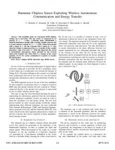
Fig. 1. Examples of digitized detector signals measured at a constant temperature.
summing up to more than 20% in the temperature range of interest (cf. Fig. 4). ) was determined • The zero-crossing time (parameter as the difference between the zero-crossing point and where the leading edge of the pulse reaches the point of its minimum value (see Fig. 1). It can be shown between the [11] that the difference of a signal due to a light pulse zero-crossing time with a decay time and the zero-crossing time due to a light pulse with a -like (immediate) light response is equal to the centre of gravity (c.o.g.) of with respect to the front edge of . The c.o.g. is proportional . Therefore, depends linearly on ; it is a to good measure of the light pulse decay time. These algorithms essentially represent numerical implementations of common methods which have been widely utilized with standard analog electronic units. We performed measurements at different ambient temperaC to C. The identiFINDER® tures ranging from unit was placed in a climatic exposure test chamber, and a 0.25 Ci Cs source was fixed on top of the detector. The climatic test chamber was set to a certain temperature, and data were taken only when the assembly was thermally equilibrated. Amand timing spectra as well as two-dimensional plitude distributions were collected. Each acquisition (2-D) step comprised a fixed number of events (pulses) collected at a certain temperature, and delivered one set of spectra for offline analysis. The temperature points were approached several times. Separate tests were made with a pulsed light-emitting diode (LED) attached to the PMT (cf. [5]). These tests demondue to temperature effects on the elecstrated that shifts in tronics are negligible compared to the scintillator effects; the indeed reflects the scintillator temperature. measured B. Results and Discussion Figs. 2 and 3 show a selection of measured and spectra. The figures demonstrate the strong temperature dependence of the system gain (reflected by the position shift of the 662 keV Cs peak), as well as of the mean zero crossing time (reflected by the shift of the timing peak position). The latter effect is only due to the scintillator temperature, whereas the system gain here
PAUSCH et al.: STABILIZING SCINTILLATION DETECTOR SYSTEMS
Fig. 2. Amplitude spectra measured at different ambient temperatures.
1851
Fig. 4. Solid lines: 662 keV peak position P ; dotted lines: mean zero-crossing time t plotted versus the ambient (= scintillator) temperature T .
Fig. 5. Sampled PA output signal (PA) and reconstructed scintillator response (L). The figure shows actual signals from one of the measurements. Fig. 3. Timing spectra corresponding to the energy spectra in Fig. 2.
includes the influence of the ambient temperature on the PMT, particularly on its photocathode. For further analysis we derived the 662 keV peak position in the amplitude spectrum and the mean zero-crossing time (center of gravity of the timing spectrum) from each data set. Fig. 4 shows these parameters as a function of ambient temperature. Yet at a moderate sampling rate with a sampling interval of 40 ns we could determine the mean zero-crossing time ns. Taking into account the slope of with an accuracy of curve shown in Figs. 4 and 5, this corresponds to an the C for the temperature when derived error of from the actually measured value of . On the other hand, a of C means a peak shift uncertainty of %. This is small compared to the typical resolution of NaI(Tl) detectors (6%–7% at 662 keV). The accuracy is, therefore, by far sufficient for proper gain stabilization. Moreover, an explicit determination of the scintillator temperature is not even required to stabilize a detector system. Rather the correlation of with can be used directly to correct the energy: We take the reference peak position at the average zero crossing time which corresponds to the actual temperais shifting the peak position to ture. A factor , thus correcting for gain shifts. This idea was implemented in a second stage of investigations.
IV. A REAL APPLICATION CASE: STABILIZING A SCINTILLATION DETECTOR AGAINST TEMPERATURE DEPENDENT GAIN SHIFTS A. Experimental Setup We employed a scheme of signal processing as realized in the new identiFINDER® -NGH units for a feasibility study of the new technique in an existing instrument. Here, the anode signals of the PMT are sampled directly. In our measurements, the mm mm NaI(Tl) scintillation detector, signals of a a detector type used in commercial identiFINDER® units, were fed to an ORTEC 113 preamplifier (PA), followed by a Canberra 2111 Timing Filter Amplifier (TFA). The TFA provided an anti-aliasing filter for the signals which were sampled with the CompuScope® waveform digitizer [12]. A customized software kit for the collection and presentation of spectra and 2-D distributions, was developed and has been used for implementing data analysis algorithms and stabilization procedures on a PC. The NaI(Tl) detector was placed inside the climatic test chamber providing for a wide range of temperatures. All electronics devices, however, were placed outside the chamber and have not been exposed to temperature slopes. This ensured the measured data not being disturbed by temperature drifts of electronics schemes.
1852
IEEE TRANSACTIONS ON NUCLEAR SCIENCE, VOL. 52, NO. 5, OCTOBER 2005
Fig. 7. Decay time spectra collected with straight (n.i.) and weighted increment (w.i.) considering the error of every individual .
Fig. 6. Two-dimensional plot of the decay time versus light output. Both parameters were extracted event by event from the sampled signals.
B. Signal Processing and Data Analysis The data analysis including the extraction of energy and decay time information from individual signals is essentially based on the digital deconvolution technique applied to digitized signals of nuclear radiation detectors [13]. As a first step, the light pulse , the scintillator response to the detected gamma ray, is reconstructed by deconvolution of the PA output signal using the known PA decay time constant (Fig. 5). The algorithm corresponds to the Moving Window Deconvolution (MWD) technique [13], [14] with a moving window width of one single unit (i.e., one sampling interval). at the trailing edge of are Subsequent samples and linked with the exponential decay of the light pulse: (1) where means the width of the sampling intervals. The individual decay time of a single light pulse is thus given by with
(2)
A representative mean value is calculated by averaging 3–5 ratios of consecutive points and on the trailing edge is estiof the reconstructed light signal . The uncertainty mated by treating fluctuations of the for different . The total light contents of a pulse, denoted as light output (parameter LO), was determined by a second MWD with the , followed by an integration of the scintillator decay time resulting rectangular pulse. versus LO measured with a Fig. 6 shows a 2-D plot of Cs source at constant temperature; the gray scale qualitatively characterizes the intensity. The distinct summit reflects the 662 keV photo peak, a broader ridge represents the Compton plateau. A projection on the LO axis yields the well known Cs energy spectrum, while a projection on the axis results in a decay time spectrum (Fig. 7). The time peak position indicates the actual scintillator decay time; the peak width is a measure of the uncertainty of the individual measurements.
Fig. 8. Variation of the ambient temperature T , the 662 keV reference peak position P , and mean decay time t with time (temperature scenario A).
Evidently the uncertainty of decreases with a rising signal amplitude: The low-energy events in Fig. 6 are widely spread along the axis, while the distribution is narrow for the 662 keV photopeak events—an expected effect because smaller signals are more influenced by noise and digitization errors. Such a distribution suggests weighting the contribution of every single event to the decay time spectrum in a way that more confident values are preferred. We used the squared reciprocal of the , as a weight factor. Now the relative error, weighted decay time spectrum is narrower and more symmetric than the straight one (Fig. 7). It is used to derive the actual mean decay time. During the single acquisition steps, temporary light output and (weighted) decay time spectra were collected and periodically analyzed. As soon as a preset of 1000–2000 events had been accumulated, the positions of the 662 keV photo peak in LO (parameter ) and the time peak position in (parameter ) were determined and stored in a log file. Then the temporary spectra were erased. The extracted parameters implicitly contain the actual system gain, composed of the scintillator light output and the PMT gain, and the decay time at the current detector temperature. A representative data log is shown in Fig. 8. It covers one night of data taking with temperature cycles from C to C with the detector placed in the climatic test chamber.
PAUSCH et al.: STABILIZING SCINTILLATION DETECTOR SYSTEMS
Pt
Fig. 9. Correlation ( ) and correction factor temperature cycles shown in Fig. 8.
1853
K (t) measured with the
Fig. 10.
Light output and stabilized energy spectra (scenario A).
The correlation characterizes the dependence of system gain on the decay time with the temperature as a hidden paramis known, one can construct the factor eter. Once (3) where means the reference peak position at , and a suitable reference temperature, which corrects the measured light output LO, representing the gamma energy , for the detector gain shifts caused by varying temperatures. It is used as a multiplier on individual pulses: The new parameter (4) does not depend on (and, therefore, not on the detector temis a well defined, reproducible correlation in perature) if the temperature range of interest. C. System Calibration The data of Fig. 8 were used to determine the correction factor , thus performing a system calibration. Fig. 9 shows a plot of versus , and the corresponding according to (3) with C. The correlation a reference temperature fixed to was fitted by a sixth-order polynomial, and (4) was implemented in the data analysis algorithm to generate the temperature-corrected energy parameter for every event. (Of course, lookup tables or other techniques to minimize the need of computing power could be used as well.) Light oputput and stabilized energy spectra are now accumulated in parallel. It is worthwhile mentioning that the system calibration only needs measurements at varying ambient temperatures covering the range of interest—neither an absolute temperature measurement, nor a specific temperature curve are required. D. System Test in Worst Case Temperature Scenarios Crucial tests of the new stabilization technique have been performed by simulating worst case conditions with different temperature scenarios. The detector, with a Cs calibration source of low activity on its top, was placed in the programmable climatic exposure test chamber.
Fig. 11. Scenario B-parameter log and stabilized energy spectrum.
Scenario A is characterized by periods of linearly increasing or decreasing ambient temperature covering the range from C to C. Typical parameter logs are presented in Fig. 8, the corresponding light output and energy spectra in Fig. 10. A comparison of the LO and distributions demonstrates the effectiveness of the stabilization procedure: In spite of the wide temperature range the stabilized spectrum shows the usual strucCs source with an acceptable resolution, whereas tures of a the photopeak is completely smeared out in LO due to gain variations of the order of 20% (cf. Fig. 9). Scenario B simulates dramatic temperature slopes. The amC bient temperature for the detector was changed from C and from C to C within a few minutes to (Fig. 11). Let us compare the temperature course with the peak position and decay time curves: It is evident that the process of thermal equilibration takes almost one hour. Nevertheless, the reference peak position and the decay time curves are well correlated, indicating the strong (“intrinsic”) coupling of both parameters. In scenario C, the temperature was varied in steps of 10 C covering the range from C to C (Fig. 12). In all cases the stabilization has worked reliably and efficiently.
1854
IEEE TRANSACTIONS ON NUCLEAR SCIENCE, VOL. 52, NO. 5, OCTOBER 2005
V. CONCLUSION
Fig. 12.
Scenario C-parameter log and stabilized energy spectrum.
TABLE I ENERGY RESOLUTION OF STABILIZED SPECTRA
E. Results and Discussion The energy resolutions of the stabilized spectra obtained in these scenarios comprising the full time measurements are given in Table I. The degradation of the energy resolution is acceptable considering the wide temperature range and the temperature slopes the detector has been exposed to. The data are confirming the naive image that a rapid, step-like change of the ambient temperature is the worst case for any detector stabilization. The assessment of these results must take into account that both, the NaI(Tl) crystal and the PMT, contribute to the gain shifts. The probably most temperature sensitive PMT component, the photocathode, is distinguished by a straight mechanical—and, thus, a good thermal—contact to the crystal. One can expect that its behavior is largely accounted for by the calibration (Fig. 9). However, there are other factors like count curve rate, applied voltages, and the individual history of the tube influencing the PMT gain, and hysteresis effects which are likely to occur [15]. Their contributions are not considered by the implemented technique. An advanced stabilization procedure should be distinguished by a separate PMT stabilization [5].
The paper demonstrates the feasibility of stabilizing NaI(Tl) detectors against gain shifts due to temperature effects by exploiting the dependence of the light pulse decay time on the scintillator temperature. The proposed method correlates a gain correction factor with the pulse shape of detector signals. The potential of this technique has been investigated experimentally. For this purpose, scintillation detector signals were sampled with a fast waveform digitizer. Pulse shape analysis algorithms were implemented in the pulse processing software. , or a parameter which is sensitive to The decay time , was extracted from every processed signal. The zero crossing time of a bipolar signal, formed by a shaping amplifier, is an example of such a parameter . We determined (or ) with an accuracy of about 2 actual values of (or ) distributions ns by calculating the centroids of (pulse shape spectra), which comprised a few hundred detector signals. The corresponding uncertainty of the gain correction is about 1%, i.e., small compared to the energy resolution of NaI(Tl) scintillation detectors (typically 7% at 662 keV). The pulse shape spectra were collected in parallel to the energy spectrum. The pulse shape distribution centroid is a sensitive indicator of the actual scintillator temperature. It considers inherently the convolution of the temperature field in the crystal with the spatial distribution of the gamma ray interactions (and, thus, of the corresponding scintillation light production) in the crystal just for the actual radiation field. The effective temperature obtained in this way for a thermally not equilibrated scintillator is adequate for estimating corrections of the measured signal amplitudes with respect to the temperature dependence of the light output. The averaging technique, of course, cannot be used to get rid of the peak broadening caused by light output variations due to crystal zones having different temperatures. Nevertheless it is the best one can do to eliminate the peak shift, i.e., to maintain the energy calibration in scintillation detectors with a nonuniform temperature distribution. This new technique can be favorably implemented in digital spectroscopic systems. The digitized signal samples taken inherit if there are only 2–3 samples sufficient information on per decay time period. There is neither additional nor modified hardware circuitry required, but an advanced algorithm of signal analysis. The extraction of a pulse shape parameter for incrementing the pulse shape spectrum should be accomplished for every detected signal. Based on the performance of an existing device [4] we estimate that this is possible without reducing the system throughput too much. Considering the typical background count rates of 30 to 100 cps measured with mm mm NaI(Tl) detector at different locations a in Germany, it is evident that the necessary statistics for a new stabilization step could be obtained within a few seconds-even if the detector is only exposed to the natural radiation background. Wehave shownthatthistechniqueiswellsuitedforstabilizinga scintillation detector system against temperature dependent gain shifts. It is of particular interest for applications with inherently stable or stabilized light detectors, e.g., LED-stabilized PMTs. Here, the only gain shift to be corrected for is due to the
PAUSCH et al.: STABILIZING SCINTILLATION DETECTOR SYSTEMS
scintillation light output which is directly correlated with the scintillator temperature and, thus, with the light pulse decay time. The situation is, at a first glance, more complicated in scintillation detectors with photodiode (PD) readout. There is another temperature dependent process, namely the light-to-charge conversion, whereas the (external) charge amplification is well controllable and can be kept stable. However, the PD is usually in a direct mechanical—and thermal—contact with the scintillator. In most situations, the scintillator temperature is therefore expected to be very close to if not identical with the PD temperature, and a system calibration including the PD gain (similar to the procedure described above) should solve the stabilization problem at a high level of accuracy. Furthermore, the new method provides an elegant means to complement and to improve another stabilization technique. Scintillators are sometimes provided with a small seed of an alpha emitter (e.g., Am). The detector signals due to these alpha particles of known energy are used as a reference for stabilizing the detector system. However, there is a temperature dependent quenching factor: The relative light output of alpha to gamma events at fixed energies depends on the scintillator temperature [16]. If the alpha source has to stabilize a gamma spectrometer, the scintillator temperature must be measured to consider this effect [3]. Our technique is an adequate means and could replace the temperature sensor and the corresponding electronics. The measurements presented here were performed with NaI(Tl) scintillators. However, the temperature dependence of the light pulse decay time or, in other materials like LaCl (Ce) [17], of the relative fractions of different decay time components in a single pulse, is a common feature of scintillator materials. These effects are reflected in the pulse shape, and they can be used to estimate the scintillator temperature and related corrections by analyzing the pulse shape. Pulse shape analysis is a unique and straightforward means to handle the problems which are due to the scintillator temperature. Other aspects and applications are touched only briefly. • Once the scintillator decay time is extracted from a representative ensemble of pulses, it can be used to adapt the signal processing (filter parameters) to the actual conditions (adaptive filtering). • The technique described in this paper provides an inexpensive means to measure the dependence of scintillator decay times on parameters like temperature, chemical composition, radiation type, etc. • A scintillator temperature measurement based on pulse shape analysis does not require any mechanical but only an optical coupling between scintillator and light detector. This suggests exploiting small scintillator samples, excited by background radiation or radioactive seeds, as contact-free, passive (remote) thermometers which are
1855
distinguished by zero power consumption. Such probes may be useful in thermally well insulated environments (vacuum). • If a scintillator crystal is provided with a static temperature field gradient (which can be done, e.g., by keeping crystal faces at different but fixed temperatures), the decay time of the individual signals can provide position information. There is, in our opinion, a strong motivation for further efforts in this interesting field. REFERENCES [1] “Technical/Functional Specifications for Border Radiation Monitoring Equipment,” International Atomic Energy Agency, Vienna, Austria, IAEA-TECDOC, Draft, 2004. [2] “American National Standard: Performance Criteria for Spectroscopy Based Portal Monitors Used for Homeland Security,” National Standards Institute, ANSI N42.38-WD-D, Draft, American Standards Institute, 2004. [3] R. Shepard, S. Wawrowski, M. Charland, H. Roberts, and M. Möslinger, “Temperature stabilization of a field instrument for uranium enrichment measurements,” IEEE Trans. Nucl. Sci., vol. 44, no. 3, pp. 568–571, Jun. 1997. [4] (2004) Digital Hand Held Spectrometer and Dose Rate Meter with Nuclide Identification, identiFINDER Data Sheet. Target Systemelectronic GmbH, Solingen, Germany. [Online]. Available: http://www.target-instruments.com/Website/PDF/e-identiFINDER.pdf [5] K. Saucke, G. Pausch, J. Stein, H. G. Ortlepp, and P. Schotanus, “Stabilizing scintillation detector systems with pulsed LEDs: A method to derive the LED temperature from pulse height spectra,” IEEE Trans. Nucl. Sci., 2005, to be published. [6] W. R. Leo, Techniques for Nuclear and Particle Physics Experiments, 2nd ed. Berlin, Germany: Springer-Verlag, 1994, p. 171 and references therein. [7] G. F. Knoll, “Radiation Detection and Measurement,” , 2 ed. New York: Wiley, 1989, p. 233, and references therein. [8] M. Tatsuyuku, “Optical Wave Guide Scintillator and Scintillation Detector,” Japanese Patent No. JP 06 258446, Patent Abstr. Japan, vol. 018, no. 654, p.1841, 1994. [9] W. R. Leo, Techniques for Nuclear and Particle Physics Experiments, 2nd ed. Berlin, Germany: Springer-Verlag, 1994, pp. 314–316. and references therein. [10] S. Normand, B. Mouanda, S. Haan, and M. Louvel, “Discrimination methods between neutron and gamma rays for boron loaded plastic scintillators,” Nucl. Instrum. Meth. Phys. Res., vol. A 484, pp. 342–350, 2002. [11] G. Pausch, W. Bohne, D. Hilscher, H.-G. Ortlepp, and D. Polster, “Particle identification in a wide dynamic range based on pulse-shape analysis with solid-state detectors,” Nucl. Instrum. Meth. Phys. Res., vol. A 349, pp. 281–284, 1994. [12] Ultra-Fast Waveform Digitizer Card for PCI Bus, CompuScope 14100 Data sheet. Gage Applied Technologies, Inc., Lachine, Canada. [Online]. Available: http://www.gage-applied.com/products/PDF/compuScope_14 100.pdf [13] J. Stein, A. Georgiev, and W. Gast, “Circuit Arrangement for the Digital Signal Processing of Semiconductor Detector Signals,” US Patent no. 5 307 299, 1994. [14] J. Stein, F. Scheurer, W. Gast, and A. Georgiev, “X-ray detectors with digitized preamplifiers,” Nucl. Instrum. Meth. Phys. Res., vol. B 113, pp. 141–145, 1996. [15] S.-O. Flyckt and C. Marmonier, Eds., Photomultiplier Tubes-Principles & Applications. Brive Cedex, France: PHOTONIS, 2002. [16] E. V. Sysoeva, V. A. Tarasov, O. V. Zelenskaya, and V. A. Sulyga, “A study of = ratio for inorganic scintillation detectors,” Nucl. Instrum. Meth. Phys. Res., vol. A 414, pp. 274–278, 1998. [17] LaCl (Ce) Lanthanum Chloride, Scintillation Material, Data sheet. Paris, France: Saint Gobain Crystals & Detectors, 2003.