Seamless Testing for Models and Code? Andreas Holzer1 , Visar Januzaj2 , Stefan Kugele3 , Boris Langer4 , Christian Schallhart5 , Michael Tautschnig1 , and Helmut Veith1 1
2 Vienna University of Technology, Austria TU Darmstadt, Germany {holzer, tautschnig, veith}@forsyte.at
[email protected] 3 4 TU M¨ unchen, Germany Diehl Aerospace GmbH, Germany
[email protected] [email protected] 5 Oxford University Computing Laboratory, UK
[email protected]
Abstract. This paper describes an approach to model-based testing where a test suite is generated from a model and automatically concretized to drive an implementation. Motivated by an industrial project involving DO-178B compliant avionics software, where the models are UML activity diagrams and the implementation is ANSI C, we developed a seamless testing environment based on our test specification language FQL. We demonstrate how to apply FQL to activity diagrams in such a way that FQL test specifications easily translate from UML to C code. Our approach does not require any additional glue or auxiliary code but is fully automatic except for straightforward source code annotations that link source and model. In this way, we can check for modeled but unimplemented behavior and vice versa, and we can also evaluate the degree of abstraction between model and implementation.
1
Introduction
In most industries, testing is the predominant approach to check the correctness of a system under development. The main challenge in testing is to establish an efficient procedure for the selection of useful test cases. Manual testing, appropriately done, requires both expertise and significant effort, and is therefore often either too imprecise or too expensive. Test automation, on the other hand, needs to incorporate domain knowledge to guide the selection of test cases. We are therefore seeing a long term trend towards model-based testing techniques where engineers provide models from which the test cases are derived. The usefulness of a set of test cases, a test suite, is naturally correlated to its impact on the system requirements. Thus, development guidelines such as DO-178B [1] insist that the test suite has to cover all system requirements. ?
Supported by BMWI grant 20H0804B in the frame of LuFo IV-2 project INTECO, by DFG grant FORTAS - Formal Timing Analysis Suite for Real Time Programs (VE 455/1-1), and by the European Research Council under the European Community’s Seventh Framework Programme (FP7/2007–2013) / ERC grant agreement no. 246858.
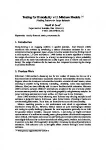
System Under Test
Model-based testing therefore needs formalisms which allow us to translate informal textual requirements into models. The modeling language typically involves UML-style automata concepts for control-centric software, or pre- and postcondition descriptions for data-centric computations. While the translation of requirements into models is done by a human, the subsequent steps lend themselves to automation. In particular, the translation of requirements into models enables us to formalize and operationalize the hitherto informal notion of “requirement coverage”: Coverage can be measured relative to model entities, e.g., as coverage of model states. Requirement coverage is thus becoming an algorithmic question. In a typical model-based testing tool Requirements chain, abstract test cases are generated at model level, and then concretized Modeling and evaluated on the system under test (SUT). The concretization step – i.e., the Model translation of abstract test cases to concrete ones – is the most difficult one, as Test Generation it requires formal models that carry suffiAbstract Test Suite cient semantic information for a seamless translation on the one hand, and a suitTest Concretization able testing mechanism for the system under test on the other hand. This mechaConcrete Test Suite nism will typically either adapt the SUT to the model level by providing a matchTest Evaluation ing high-level API or by employing test scripts that drive the SUT; it may also Test Results combine both methods. In the evaluation step, the achieved source code coverage is Fig. 1. Model-based testing process observed and failures in the program behavior are checked for. Figure 1 summarizes this basic model-based testing work flow. Despite its success in both academia and industrial practice, model-based testing has not realized its full potential yet: – Requirement coverage on the model is often lacking a precise definition, and only implicitly defined by existing tool chains. Most available tool chains only support specific hard-coded coverage criteria, such as node or transition coverage. We need a more flexible requirement specification formalism along with tool support to help the test engineer develop the test suite incrementally, to tailor test specifications for relevant goals and to deal with incomplete implementations and/or evolving requirements. – Test concretization is typically based on manually crafted test scripts. Besides being error-prone, inflexible, and expensive, the manually crafted adaption code may introduce hard-to-detect errors and jeopardizes the formal traceability of requirements. In this paper, we describe a seamless framework for model-based testing which addresses these issues:
(a) Versatile Coverage Specifications. In Section 2, we demonstrate on the example of UML activity diagrams that our test specification language FQL [2] (which was previously used for ANSI C source code) is a versatile, simple, and precise formalism to specify model-level coverage criteria. (b) Automated Test Generation. In Section 3.1, we show how to use our test input generator FShell [3, 4] to automatically compute model-level test cases in accordance with the coverage specifications. (c) Automated Test Concretization. In Section 3.2, we use the model-level test cases as patterns for concrete test cases. Driven by these patterns, FShell automatically computes test inputs for the implementation. Thus, we replace hand-written test scripts by a highly automated seamless procedure. (d) Improved Traceability. Our concretization mechanism is tied to a traceability relation between models and implementation which is based on simple (but necessarily manual) FQL-based annotations. Section 3.3 shows how to compute model/implementation inconsistencies using this relation. (e) Applicability in DO-178B Processes. We study the applicability of our testing approach to DO-178B compatible system development processes in Section 4. We developed a plug-in for TOPCASED [5] that implements our methodology for models given as activity diagrams and systems under test written in ANSI C.
2
Seamless Test Specifications in FQL
We first review the concepts of FQL, a coverage specification language originally designed for coverage criteria in imperative programming languages such as ANSI C. For a detailed and complete description of FQL cf. [2]. In Section 2.2 we adapt FQL to support model-based testing and exemplify this step on UML activity diagrams.
1 2
int max(int x, int y) { int tmp;
if (x >= y) tmp = x; 6 else 7 L: tmp = y; 4 5
return tmp;
9
2.1
FQL in a Nutshell
10
}
In FQL, programs are represented by control flow 1 automata (CFA) [6], which are essentially control int x, y, tmp flow graphs, bearing the statement labels on their edges instead of their nodes. Figure 2 shows an [x >= y] 4 [x < y] ANSI C function that returns the maximum value 5 7 of two given parameters, and below, its CFA. A tmp := x condition, e.g., x >= y at Line 4, is modeled by 9 L: tmp := y two edges, one for each evaluation of the condition: return tmp Edge (4, 5) assumes that x >= y holds whereas 10 edge (4, 7) assumes x < y. The nodes, edges, and paths in a CFA form the potential test targets, e.g., if we want a test suite that covers all state- Fig. 2. Sample C function ments, we need to reach each CFA node via some and corresponding CFA
test input, while for condition coverage, we need to reach each edge representing the outcome of a condition (edges (4, 5) and (4, 7) in our example). To specify test targets in FQL, we use filter functions. Each filter function calculates a subgraph of a given CFA, e.g., the filter function ID computes the identity function. There are also filter functions referring to code structures needed by standard coverage criteria, such as basic block coverage or condition coverage: @BASICBLOCKENTRY yields all basic block entries and @CONDITIONEDGE yields all evaluations of conditions. In the example above, ID yields the CFA itself, @BASICBLOCKENTRY yields the subgraph containing all nodes of the CFA and the CFA edges (1, 4), (5, 9), (7, 9), and (9, 10), whereas @CONDITIONEDGE yields the subgraph containing the nodes 4, 5, and 7 and the CFA edges (4, 5) and (4, 7). The filter function @LABEL(L) refers to the CFA edge that represents the source code annotated with code label L, e.g., CFA edge (7, 9) in the example above. We can also refer to the entry and exit edges of the function max, i.e., the edges (1, 4) and (9, 10), respectively, by using the expressions @ENTRY(max) and @EXIT(max), respectively. Filter functions encapsulate the programming language dependent part of FQL; all further aspects, as described below, are independent of the programming language. Using the operators NODES, EDGES, and PATHS, we select the nodes, edges, or paths in the subgraph identified by filter functions. For example, NODES(ID) refers to the CFA nodes 1, 4, 5, 7, 9, and 10, and the expression EDGES(@LABEL(L)) refers to the singleton set containing the CFA edge (7, 9). The operator PATHS(F , k) takes a filter function F and a positive integer bound k as parameters and yields the set of paths in the subgraph identified by F which pass no CFA edge more than k times. In the example above, PATHS(ID, 1) denotes the two sequences h(1, 4), (4, 5), (5, 9), (9, 10)i and h(1, 4), (4, 7), (7, 9), (9, 10)i. To build patterns from these node, edge, and path sets, we recombine these sets into patterns with the standard regular expression operators, i.e., ‘.’, ‘+’, and ‘*’, denoting concatenation, alternative, and the Kleene star. In the following we refer to these patterns as path patterns. For example, let Q denote the expression EDGES(ID)*.EDGES(@CONDITIONEDGE).EDGES(ID)*, then, evaluated on the CFA in Figure 2, Q specifies the paths that enter a condition edge after finitely many CFA edges, i.e., either edge (4, 5) or (4, 7), and, finally, reach the program exit after finitely many further steps. Since EDGES is used in most cases, FQL allows to omit it, i.e., the pattern above can be abbreviated as ID*
[email protected]*. Moreover, the sets constructed with NODES, EDGES, and PATHS may be further qualified with predicates, e.g., the path pattern ID*.{x > 10}.@LABEL(L).ID* requires that code label L is reached at least once when variable x is greater than 10. Due to the Kleene star operator in the example expression Q, its language contains infinitely many words, given as finite sequence of predicates, CFA nodes, and CFA edges (here, we consider a path as a sequence of edges). However, when testing, we need a finite set of test targets, and therefore, FQL distinguishes between path patterns and coverage patterns: Both are regular expressions built from predicates, the operators NODES, EDGES, PATHS, and the concatenation and alternative operators ‘.’ and ‘+’. However, only path patterns are allowed to
use the Kleene star ‘*’, while coverage patterns are allowed to encapsulate path patterns. Such path patterns are stated in quotes and match an execution fragment that satisfies one of the words in the language of the path pattern. For example, in contrast to the infinite language of Q, the language of the coverage pattern "EDGES(ID)*".EDGES(@CONDITIONEDGE)."EDGES(ID)*" contains only two words: One that requests a program execution that passes after finitely many steps the edge (4, 5) and proceeds with finitely many further steps to the program exit, as well as the analogous word with edge (4, 7) instead of (4, 5). An FQL query has the general form cover C passing P , where C is a coverage pattern and P is a path pattern. It requires a test suite which (i) contains for each word in C at least one matching test case, and (ii), contains only test cases matched by P . For example, to achieve condition coverage with the constraint that each test case reaches code label L while x > 10 holds, we use the query cover "ID*".@CONDITIONEDGE."ID*" passing ID*.{x > 10}.@LABEL(L).ID*
The passing clause is optional and defaults to passing ID* upon omission. 2.2
FQL for UML Models [list is not empty]
The graphical representation of transitionselect first based UML modeling formalisms like UML element activity diagrams or UML state machines [7] select next lend themselves to an interpretation as conelement trol flow automata. Since these diagrams use a different semantics for their nodes and edges [element is print not null] element than FQL for its CFA, we have to define new [element is null] filter functions. As stated above, filter functions are the interface of FQL to different programming and modeling formalisms, hence, Fig. 3. Model M: Printing a list apart from filter functions, the definitions of path and coverage patterns remain unchanged. Using UML activity diagrams, we exemplify the application of FQL to UML models: Figure 3 shows an example diagram M, where the behaviors of the action nodes and guards are given informally, i.e., as plain text. The diagram describes the printing functionality for elements of a linked list. Guarded by the assertion that the input list is not empty, the head of the list is selected and printed, then its successor is processed, and so forth, until every element of the list has been printed. M contains all node types currently supported by our TOPCASED plug-in: Action ( ), decision and merge ( ), initial ( ), and activity final nodes ( ). We consider an activity diagram as a finite automaton whose transitions can be labeled with guards and whose activity nodes are labeled with operations describing the behavior of the node. Guards and operations can be plain text, as in the example, or be formal with an exact semantics like UML OCL expressions. The operation of a call-behavior node is given as an associated subdiagram. The semantics of the operators NODES, EDGES, and PATHS does not change and, therefore, we can express standard coverage criteria for model-based testing immediately as FQL specifications. Table 1 gives FQL queries for all-states
Table 1. Coverage criteria for model-based testing stated as FQL queries Coverage Criterion
FQL Query
All-states Coverage All-transitions Coverage All-transition-pairs Coverage
"ID*".NODES(ID)."ID*" "ID*".ID."ID*" "ID*".ID.ID."ID*"
coverage, all-transitions coverage, and all-transition-pairs coverage (cf. [8]). The simplest criterion, all-states coverage, requires every node in the model to be covered by a test case. All-transitions coverage requests a test suite that covers every transition in the model. Finally, all-transition-pairs coverage requires a test case for each pair of consecutive transitions in the model. Besides standard coverage criteria, we are also able to express coverage criteria specific to the model for which we want to generate tests. This enables us, e.g., to prioritize test generation with respect to most critical features of the system being developed. Furthermore, the test designer can specify semantic information present in the model as text only, in the FQL query. For example, the query cover "ID*".ID."ID*" passing ID*.NODES(@ACTION(print element)).ID*
requires transition coverage for the model in Figure 3 where the action print element is reached at least once encoding the informally specified constraint that only nonempty lists are possible as inputs. Transitions in an activity diagram are always labeled with a guard (defaulting to true, if blank). For simple conditions, i.e., no Boolean combinations of predicates, we consider the guarded transition as a CFA edge labeled with an assume statement as introduced in Section 2.1. More complex guards, however, result in condition graphs which contain nodes and edges for all involved primitive conditions. For example, an expression PATHS(@GUARDS, 1) denotes all paths in the condition graphs resulting from guards. Note, as UML OCL constraints do not contain loops, the bound 1 is sufficient to refer to all possible paths inside the condition graph resulting from such a guard. So, to specify a test suite that simultaneously achieves path coverage for all guard conditions and covers all nodes in the activity diagram, we state the FQL query cover "ID*".(NODES(@ACTIVITYNODES) + PATHS(@GUARDS, 1))."ID*". Thus, we are able to refer to elements of the graphical representation of an activity diagram as well as to structural elements of the guards within the same formalism, i.e., an FQL query. In Section 3.1, we show how we generate test cases for FQL specifications stated on activity diagrams.
3
Test Process
We present our test process following its steps test generation (Section 3.1), test concretization (Section 3.2), and test evaluation (Section 3.3) as depicted in Figure 1 and use the example diagram M given in Figure 3 for illustration. 3.1
Test Generation
Via a generation query Qg we specify the coverage we want to achieve at model level. For example, the query cover PATHS(ID, 1) requires a test suite where
all loops in M are either skipped or traversed once. We realize the generation of model-level tests by translating M into a C program M0 and Qg into an FQL specification Q0g . Then, we use FShell to generate a test suite for M0 that achieves the coverage required by Q0g . Listing 1 shows the C code generated from M. Each diagram node corresponds to a code label and a call to a logging mechanism, e.g., the code labeled with PL ENTRY corresponds to the initial node in Figure 3. When program execution reaches this code, we log the unique identifier PL ENTRY ID of the initial node. Flows between two nodes are realized via goto statements. In case of a decision node, a switch structure realizes the branching control flow. We use exactly one C function per activity diagram and realize calls to subdiagrams as function invocations (there are none in this example). The function ‘ decision ’, which is declared but not defined, controls the flow. On evaluating Q0g on M0 , FShell generates the definition of the function ‘ decision ’ as a representation of the computed test suite: For the running example, the generated definition is shown in Listing 2. We use the global variable fshell2 tc selector to choose one of the generated test cases, such that ‘ decision ’ returns the sequence of decisions necessary to guide the execution through the selected test case. After compiling and linking M0 together with the generated function ‘ decision ’, the execution of the resulting program produces a log which identifies the model elements passed during execution. Thereby, we obtain a model-level test case CiM as a sequence of model elements. Figure 4 depicts the model-level test suite SM = {C1M , C2M } generated for the query Qg = Q0g = cover @PATHS(ID, 1). After inspecting SM , the test engineer either releases the suite or adjusts Qg to enhance the suite until achieving requirements coverage on the model. A model with an executable semantics can improve the test generation step by encoding the formal semantics of the model elements into the generated C program, such that the generated test cases are more meaningful and spurious test cases can be avoided. We can encode guards with a formal semantics into the generated C code with FShell’s support for assumptions: FShell supports a C function CPROVER assume with a semantics analogous to a guard, i.e., FShell considers only those program executions which do not violate any assumption. 3.2
Test Concretization
In order to concretize model-level test cases, such as those shown in Figure 4, we need to relate model entities with source code elements. This relation yields additional traceability information between model and implementation, which we exploit in the test evaluation described in Section 3.3. Continuing the example, we use the hand-coded program in Listing 3 as implementation of the model shown in Figure 3 and, already annotated, in Figure 5: To establish links between model and source code, we rely on FQL’s expressiveness in referring to specific implementation elements, and use annotations consisting of two parts: (i) Labels added to the relevant source code locations, and (ii) matching annotations at activity diagram nodes. As shown in Figure 5, we associate model elements with FQL filter expressions and thereby refer to
1 2
// FShell generates this function extern int decision();
void diagram M() { // initial 6 PL ENTRY: log(PL ENTRY ID); 7 goto PL 1; 8 // ” list is not empty” has no code 4
5
// select first element PL 1: log(PL 1 ID); goto PL 12 // merge node 13 PL 2: log(PL 2 ID); goto PL 14 // decision node 15 PL 3: log(PL 3 ID); 16 switch (decision()) { 17 // element is not null 18 case 0: goto PL 4; 19 // element is null 20 default: goto PL EXIT; 21 } 22 // print element 23 PL 4: log(PL 4 ID); goto PL 24 // select next element 25 PL 5: log(PL 5 ID); goto PL 26 // activity final 27 PL EXIT: log(PL EXIT ID); 28 } 10 11
2; 3;
extern unsigned fshell2 tc selector ; int decision (){ 3 static unsigned idx = 0; 4 int retval1 [1] = { 8192 }; 5 int retval2 [2] = { 0,524288 }; 6 switch ( fshell2 tc selector ) { 7 case 0: return retval1[idx++]; 8 case 1: return retval2[idx++]; 9 } 10 } 1 2
Listing 2. Generated C function decision Model-level test case C1M : enter print list
@ENTRY(print list)
select first element
@LABEL(A1)
leave print list
@EXIT(print list)
Model-level test case C2M : 5;
enter print list
@ENTRY(print list)
2;
select first element
@LABEL(A1)
print element
@LABEL(A2)
select next element
@LABEL(A3)
leave print list
@EXIT(print list)
int main() { 31 diagram M(); 32 return (0); 33 } 30
Listing 1. Generated C program M0
Fig. 4. Model-level test suite SM = {C1M , C2M } with links to source code (see Section 3.2)
the SUT via the corresponding labels. For example, we link the action select first element with the filter function expression @LABEL(A1) which identifies the assignment labeled with A1 in Listing 3. Entry and exit nodes of activity diagrams are annotated with @ENTRY(print list) and @EXIT(print list), respectively. Building upon this mapping, we automatically translate the model-level paths of SM into sequences of code labels. From each such sequence, a passing clause Pic for the implementation is computed such that every matching execution of the implementation concretizes the corresponding model-level test case CiM . For a precise description of the desired executions, the code label sequences must be augmented with restrictions on the permitted statements between points of code prescribed by the model-level path. Consider, e.g., the model-level test case C1M : After select first element (i) no other action node must be reached and (ii) function print list must not be left and/or re-entered before reaching leave print list.
void print list (struct list ∗ p list ) { struct list element∗ cur elem; 3 assert ( p list != 0 && 4 p list −>head != 0); 5 A1: cur elem = p list−>head; 6 while (cur elem != 0) { 7 A2: if (cur elem−>allocated != 0) 8 printf (”ALLOCATED\n”); 9 else 10 printf (”FREE\n”); 11 A3: cur elem = cur elem−>next; 12 } 13 } 1
@ENTRY(print list)
2
Listing 3. Realization of print list
[list is not empty] @LABEL(A1)
@LABEL(A3)
select next element
@LABEL(A2)
print element
select first element
[element is not null] [element is null]
@EXIT(print list)
Fig. 5. Printing elements of a linked list with additional FQL annotations
These properties are best described using FQL’s set-theoretic operations setcomplement, “NOT”, and set-union, “|”. We use FShell’s C-style macro feature and derive from the model M a suitable definition of a macro m nodes to denote the set of all model-level entities. For our running example m nodes is defined to be @LABEL(A1)|@LABEL(A2)|@LABEL(A3) | @ENTRY(print list)|@EXIT(print list). We then use this macro to describe the desired restriction as "NOT(m nodes)*". For example, C1M concretizes to P1c : P1c = passing @ENTRY(print list) . "NOT(m nodes)*" . @LABEL(A1) . "NOT(m nodes)*" . @EXIT(print list)
To compute the concrete (implementation level) test suite SI , we use a concretization query Qc , e.g., Qc = cover "ID*".@CONDITIONEDGE."ID*". We compute for each passing clause Pic a concrete test suite SiI by evaluating Qic , which combines Qc and Pic . Thus, FShell produces for each model-level test case CiM with SiI a test suite which covers as many test goals of Qc as possible such that its test cases only follow Pic . For Qc = cover "ID*".@CONDITIONEDGE."ID*" this results in covering all branches along the path prescribed by Pic . In our example, for the model-level test case C1M we obtain: Q1c = cover "ID*".@CONDITIONEDGE."ID*" passing @ENTRY(print list) . "NOT(m nodes)*". @LABEL(A1) . "NOT(m nodes)*" . @EXIT(print list)
We pass the source code of the SUT, macro definitions, and Qic to FShell to compute SiI . Depending on the relationship between model and implementation, each generated suite SiI may contain none, one, or several concrete test cases, i.e., i,ki i SiI = {Ci,1 final executable I , . . . , CI }, where S kii ≥ 0 denotes the size of SI . The test suite SI is the union i SI of all individual test suites SiI . For our example and Q1c , FShell finds all test goals to be infeasible, i.e., S1I = ∅. For Q2c , however, FShell will return two test inputs: 2,2 S2I = {C2,1 I , CI } = { ∗ p list ={.head = {.allocated = 0, .next = NULL}}, ∗ p list ={.head = {.allocated = 1, .next = NULL}}}
All model level test cases should concretize to singleton sets; we study the reasons for the deviations occurring in our running example in the next section.
3.3
Test Evaluation
Finally, we analyze the implementation-level test suite SI to identify mismatches in the relationship between model and implementation and execute the test cases in SI to find errors in the implementation. We categorize the potentially occurring deviations into the deficiencies (D1) to (D4), as discussed below. Depending on the quality assurance and certification constraints to be obeyed, some of these deficiencies are perfectly acceptable while others require an update of implementation, model, or both. Concretization Deficiencies. First, we consider the deficiencies which are identii,ki fiable from the structure of SI and its constituent suites SiI = {Ci,1 I , . . . , CI }. Please recall the mapping between model and implementation, as established by our annotations: Each implementation construct is ideally labeled with the corresponding node from the model and vice versa. If this is the case, each model-level test case CiM yields a test suite SiI with exactly one test case Ci,1 I . Otherwise, we observe one of the following two deficiencies. – Implementation Poverty (D1): There is a test suite SiI with |SiI | = 0. Poverty occurs when a model-level test case CiM does not yield any concrete test case. Then either incomplete implementations are tested, or the model overapproximates the implementation behavior. For our example and the model-level test suite shown in Figure 4, the first query Q1c yields an empty test suite S1I , i. e., we observe (D1). Our model cannot formally describe control conditions and thus the model-level test case generation does not consider the fact that print list processes only nonempty lists. This precondition is enforced in Listing 3, where we assert p list −>head != 0, such that cur elem is initialized at label A1 with a non-zero value. Therefore, the condition of the while loop cannot evaluate to false and the loop body is entered at least once. – Implementation Liberty (D2): There is a test suite SiI of size |SiI | > 1. Liberty occurs, if the activities visited by CiM are uncoverable with a single concrete test case. This happens whenever the model is more abstract than the implementation, where the precise meaning of “more abstract” depends on the coverage criteria employed; mostly, it means that some model activities necessitate non-trivial control flow in the implementation. Depending on the quality constraints, this can be perfectly acceptable. However, in critical systems, such as DO-178B compliant software, undocumented code is not allowed (cf. [1], §6.3.4) and liberty indicates a violation thereof. In our example, as discussed in [element is allocated] [element is not allocated] Section 3.2, S2I contains two concrete test cases, revealing liberty in print print “ALthe action print element. Both test “FREE” LOCATED” cases contain a list with a single element where its field allocated is ei@LABEL(A4) @LABEL(A5) ther initialized with 0 or 1. The reason for this implementation liberty Fig. 6. Activity diagram of if structure
is the unmodeled if −then−else construct in the while loop of Listing 3. We choose to correct this situation by replacing the action print element with a call behavior action that is associated with the diagram shown in Figure 6. We also label both, the source code and the respective model entities, to relate them with each other (we do not show the new labels in the listing). Evaluation Deficiencies. The remaining two deficiencies are discovered by analyzing the concrete test suite SI —once by checking whether it achieves coverage on the implementation, and once by running it. FShell provides support for automatically constructing a test harness from SI . This driver for the SUT enables execution and proper evaluation. The check for coverage is controlled by the evaluation query Qe : This query is determined by the applicable certification standard, which demands to satisfy a certain structural coverage at implementation level with a test suite achieving requirements coverage at model level, i.e., Qe amounts to an adequacy criterion for the generated test suite. For example, DO-178B Design Assurance Level C requires statement coverage, i.e., Qe would be cover "ID*".NODES(ID)."ID*". – Implementation Anarchy (D3): The test suite SI does not satisfy the evaluation query Qe on the implementation. Anarchy relative to Qe occurs when the implementation is not fully modeled, requiring—depending on the applicable certification standard—either corrections in the model and/or implementation, or a rationale explaining the omission, e.g., if third-party code is involved. Given the expressiveness of FQL, such omissions can be formally documented by adjusting Qe to require only coverage of code fragments which are relevant to this development process. – Implementation Error (D4): The implementation exhibits erroneous behavior on executing the test suite SI . The last deficiency, implementation error, occurs upon assertion violations and unexpected program outputs, and requires in all likelihood a correction to bring implementation and model into mutual correspondence. While checking assertions does not require any further provisions, error detection necessities test oracles for monitoring the program output. If the model lacks an executable semantics, as in our example, oracles could only be obtained from additional annotations given by the user (editing the automatically generated SUT driver is possible, but undesirable). For models with an executable semantics, the guards translate to assertions, which serve as test oracles in the generated SUT driver. Seamless Traceability. Note that if implementation poverty, liberty, and anarchy (D1-3) do not occur in a testing process, then model and source code implement essentially the same control flow. Moreover, the annotations used in model and implementation precisely document the relationship between them and enable the mutual traceability of requirements and program features.
4
Prototype Evaluation
In our joint project INTECO, we used our TOPCASED plug-in to apply our approach to a memory manager which is part of a helicopter pilot assistance and mission planing system. This memory manager is implemented in 526 lines of ANSI C code6 and should avoid memory fragmentation caused by dynamic allocations. To do so, it provides an API that enables the programmer to gather individual chunks of memory in a statically acquired memory area. We studied the feasibility of our approach using UML activity diagrams describing the behavior of API functions. The derived requirements for the memory manager yielded 21 activity diagrams, 17 of them are implemented as C functions, two are part of these functions, and the remaining two are macros. Amongst these diagrams, there were at most 13 action nodes, two decision nodes, and one loop in an activity. Albeit small in size, our prototypical case study is based on an industrial avionics software component, demonstrating the capability of our tool chain to deal with real-world C code. The initial concretization revealed several errors in design and coding: The order of the action nodes of one activity diagram was not correctly reflected in the C code of the implementation. Thus, both, implementation anarchy (D3) and poverty (D1) occurred: Some code remained unreachable in the paths prescribed by the abstract test cases, resulting in (D3), and one further test case was impossible to concretize, leading to (D1). We did not observe implementation liberty, which was an important aspect as DO-178B compatible development requires full traceability between derived low level requirements (which were here modeled using activity diagrams) and implementation. During execution, no further implementation errors (D4) were found. Unfortunately, we cannot publish the model and source code studied here, as it is covered by a nondisclosure agreement. But as soon as possible, we will publish our TOPCASED plugin under an open source license on the web7 .
5
Related Work
The basic principles behind model-based testing were described by Chow in 1978 [9], the term model-based testing was coined and further refined by Dalal et al. [10]. Their work includes automated test input generation and focuses on boundary value testing. Most existing formalisms for test specifications focus on the description of test data, e.g., TTCN-3 [11] and the UML 2.0 Testing Profile [12], but none of them allows to describe structural coverage criteria. Friske et al. [13] have presented coverage specifications using OCL constraints. Although OCL provides the necessary operations to speak about UML models, it has not been intended for coverage specifications, and henceforth, complex coverage specifications might be hard to express and read. At the time of publication, no tool 6 7
Source lines of code (SLOC), measured with David A. Wheeler’s SLOCCount tool. http://code.forsyte.de/fshell
support for the framework in [13] has been reported. Hessel et al. [14] present a specification language for model-level coverage criteria that uses parameterized observer automata. Test suites for coverage criteria specified in this language can be generated with Uppaal Cover [15]. The approach of [16] is similar to our work but targeted at Java programs: Their focus lies on automatic test execution, observation of traces, and test input generation. The latter is, however, performed using program specific generators. In [17], the generation of test inputs for Simulink models is realized via a translation of models to C code. This code is subsequently processed by a tool which is—like FShell—built upon CBMC [18]. The AGEDIS project [19] also aims at automating model-based testing. Their test execution directives are the necessary adapters to translate model-level tests to executable code. In AGEDIS it is assumed that these directives are part of the input provided by the user. The UniTesK tool chain [20] calls adapters mediators, which have to be created R tools [21], we (semi-)manually with some wizards. Compared to the T-VEC focus on UML activity diagrams instead of Simulink models and we support automated test generation for informal models. One of the most advanced testing tool chains is Spec Explorer [22]. It combines model-based testing with various techniques for automated test case generation. Spec Explorer works on Spec# models and .Net code and uses AsmL [23] as formal foundation. Spec Explorer analyzes a simulation relation between model and implementation and uses a mapping as coarse as functions (which is trivial in our case, because we have a single activity diagram per C function). Spec Explorer includes techniques for test case selection—however, they are not as fine grained as FQL. Building upon Spec Explorer, Kicillof et al. [24] describe an approach that combines model-level black-box testing with parametrized white-box unit testing. They generate unit tests for an extended version of activity diagrams and concretize these tests via white-box test case generation. Their work aims at generating high implementation coverage, while we focus on a DO178B compatible processes, i.e., we only measure the achieved implementation coverage and check for possible deficiencies. Black-box approaches, such as input/output conformance (ioco) testing as performed in the TorX framework [25], require a different kind of mapping, which focuses on interface descriptions. But even in such cases, FShell is applicable, albeit we could use a fraction only of its power. There exist several approaches that cover specifically the test input generation part for UML models: In the tradition of automata-theoretic methods, the most common [26] approaches employ UML state machines [27, 28] and interaction diagrams [29], respectively. Test case generation based on activity diagrams for Java programs was introduced by Chen et al. in [30–32]: They propose in [30] a method to generate random test cases, and introduce in [31] a coverage-directed approach using the model checker NuSMV [33]. While their first, random-based approach, is unlikely to achieve good coverage, their second approach suffers from the state space explosion problem and appears to be unscalable. Kundu and Samanta [34] present an extension of [31, 32] which is aimed at concurrent
Java applications and uses much more abstract models leading to test cases which are apparently not executable without additional processing.
6
Conclusion
Many certification standards are demanding tests generated from requirementderived models, and ask for seamless traceability of low-level requirements. In this paper, we provide a solution to both challenges: First, exploiting the expressiveness and adaptability of FQL, we specify model-level test suites and generate them with FShell. Second, relying on annotations of model and source, we concretize the model-level test suites to the implementation. As this step does not involve adaption code but only annotations, it enables us to assess the relation between model and source in a precise manner. Although our example and case study consider low level models, our approach is not limited to that: High-level models can refer to function calls instead of code labels, or both of them. Our prototype demonstrates that our approach is applicable to industrial projects and does indeed find deficiencies in these examples. We are currently working on a larger case study with industrial collaborators. Future research goals include automatic generation of source code stubs and test oracles. We want to thank the anonymous reviewers for their useful remarks.
References 1. RTCA DO-178B: Software considerations in airborne systems and equipment certification (1992) 2. Holzer, A., Schallhart, C., Tautschnig, M., Veith, H.: How did you specify your test suite. In: ASE. (2010) 407–416 3. Holzer, A., Schallhart, C., Tautschnig, M., Veith, H.: FShell: systematic test case generation for dynamic analysis and measurement. In: CAV. (2008) 209–213 4. Holzer, A., Schallhart, C., Tautschnig, M., Veith, H.: Query-driven program testing. In: VMCAI. (2009) 151–166 5. Farail, P., Gaufillet, P., Canals, A., Le Camus, C., Sciamma, D., Michel, P., Cr´egut, X., Pantel, M.: The TOPCASED project: a toolkit in open source for critical aeronautic systems design. In: ERTS. (2006) 54–59 6. Henzinger, T.A., Jhala, R., Majumdar, R., Sutre, G.: Lazy abstraction. In: POPL. (2002) 58–70 7. OMG: UML 2.0 Superstructure Specification. Technical Report ptc/04-10-02, Object Management Group (2004) 8. Utting, M., Legeard, B.: Practical Model-Based Testing: A Tools Approach. Morgan Kaufmann Publishers Inc. (2006) 9. Chow, T.: Testing software design modeled by finite-state machines. IEEE Transactions on Software Engineering SE-4(3) (1978) 178 – 187 10. Dalal, S.R., Jain, A., Karunanithi, N., Leaton, J.M., Lott, C.M., Patton, G.C., Horowitz, B.M.: Model-based testing in practice. In: ICSE. (1999) 285–294 11. Din, G.: TTCN-3. In: Model-Based Testing of Reactive Systems. (2004) 465–496 12. Schieferdecker, I., Dai, Z.R., Grabowski, J., Rennoch, A.: The UML 2.0 testing profile and its relation to TTCN-3. In: TestCom. (2003) 79–94
13. Friske, M., Schlingloff, B.H., Weißleder, S.: Composition of model-based test coverage criteria. In: MBEES. (2008) 87–94 14. Blom, J., Hessel, A., Jonsson, B., Pettersson, P.: Specifying and generating test cases using observer automata. In: FATES. (2004) 125–139 15. Hessel, A., Larsen, K.G., Mikucionis, M., Nielsen, B., Pettersson, P., Skou, A.: Testing real-time systems using UPPAAL. In: FORTEST. (2008) 77–117 16. Artho, C., Drusinsky, D., Goldberg, A., Havelund, K., Lowry, M.R., Pasareanu, C.S., Rosu, G., Visser, W.: Experiments with test case generation and runtime analysis. In: ASM. (2003) 87–107 17. Brillout, A., He, N., Mazzucchi, M., Kroening, D., Purandare, M., R¨ uummer, P., Weissenbacher, G.: Mutation-based test case generation for simulink models. In: FMCO. (2009) 208–227 18. Clarke, E.M., Kroening, D., Lerda, F.: A Tool for Checking ANSI-C Programs. In: TACAS. (2004) 168–176 19. Hartman, A., Nagin, K.: Model driven testing - AGEDIS architecture interfaces and tools. In: First European Conference on Model Driven Software Engineering. (2003) 1–11 20. Kuliamin, V.V., Petrenko, E.K., Kossatchev, E.S., Bourdonov, I.B.: Unitesk: Model based testing in industrial practice. In: First European Conference on Model Driven Software Engineering. (2003) 55–63 21. T-VEC. http://www.t-vec.com/ (January 2011) 22. Veanes, M., Campbell, C., Grieskamp, W., Schulte, W., Tillmann, N., Nachmanson, L.: Model-based testing of object-oriented reactive systems with spec explorer. In: FORTEST. (2008) 39–76 23. Barnett, M., Grieskamp, W., Nachmanson, L., Schulte, W., Tillmann, N., Veanes, M.: Towards a tool environment for model-based testing with asml. In: FATES. (2003) 252–266 24. Kicillof, N., Grieskamp, W., Tillmann, N., Braberman, V.A.: Achieving both model and code coverage with automated gray-box testing. In: A-MOST. (2007) 1–11 25. Tretmans, J., Brinksma, E.: TorX: Automated model-based tesing. In: First European Conference on Model-Driven Software Engineering. (2003) 31–43 26. Dias Neto, A.C., Subramanyan, R., Vieira, M., Travassos, G.H.: A survey on model-based testing approaches: a systematic review. In: WEASELTech. (2007) 31–36 27. Weißleder, S., Schlingloff, B.H.: Deriving input partitions from UML models for automatic test generation. In: MoDELS Workshops. (2007) 151–163 28. Chevalley, P., Th´evenod-Fosse, P.: Automated generation of statistical test cases from UML state diagrams. In: COMPSAC. (2001) 205–214 29. Nayak, A., Samanta, D.: Model-based test cases synthesis using UML interaction diagrams. SIGSOFT Softw. Eng. Notes 34(2) (2009) 1–10 30. Chen, M., Qiu, X., Li, X.: Automatic test case generation for UML activity diagrams. In: AST. (2006) 2–8 31. Chen, M., Mishra, P., Kalita, D.: Coverage-driven automatic test generation for UML activity diagrams. In: GLSVLSI. (2008) 139–142 32. Chen, M., Qiu, X., Xu, W., Wang, L., Zhao, J., Li, X.: UML activity diagrambased automatic test case generation for java programs. The Computer Journal 52(5) (2009) 545–556 33. Cimatti, A., Clarke, E., Giunchiglia, F., Roveri, M.: NuSMV: a new Symbolic Model Verifier. In: CAV. (1999) 495–499 34. Kundu, D., Samanta, D.: A novel approach to generate test cases from UML activity diagrams. Journal of Object Technology 8(3) (2009) 65–83