reverse engineering will gain design cost and market share advantages. ..... documentation can reduce the degree of information available to an RE team. ..... Notes in Computer Science, M. Wiener, Ed. Berlin, Germany: Springer,. 1999.
2008 14th IEEE International Conference on Parallel and Distributed Systems
Secure embedded systems: the threat of reverse engineering Ian McLoughlin
Abstract— Companies releasing newly designed embedded products typically recoup the cost of development through initial sales, and thus are unlikely to welcome early competition based around rapid reverse engineering of their products. By contrast, competitors able to shorten time-to-market though reverse engineering will gain design cost and market share advantages. Reverse engineering for nefarious purposes appears to be commonplace, and has significant cost impact on industry sales and profitability. In the Embedded Systems MSc programme at Nanyang Technological University, we are aiming to raise awareness of the unique security issues related to the reverse engineering of embedded systems. This effort is largely through devoting 50% of the Secure Embedded Systems course, ES6190 to reverse engineering (the remainder to traditional security concerns). This paper covers the reverse engineering problem scope, and our approach to raising awareness through the Secure Embedded Systems course. A classification of hardware reverse engineering steps and mitigations is also presented for the first time, with an overview of a reverse engineering curriculum. Since the quantity of published literature related to the reverse-engineering of embedded systems lies somewhere between scarce and nonexistent, this paper presents a full overview of the topic before descussing educational aspects related to this.
I. I NTRODUCTION The release of a new digital electronic product is often the culmination of a long, arduous and expensive design process. Recuperation of these costs is naturally the first major target of sales revenue for any design company. In general, this sales revenue is increased by earlier market entry than competing products. Any pioneering design and manufacturing company (DMC) can naturally expect some competition in time, which often improves upon their original design. However the first few months of sales in an un-crowded market play an important part in overall profitability for new product releases. In an ideal world, that company could expect that any newly arrived competitor products would have incurred similar development expense, and thus have similar cost structures to their own. Economics can change substantially when a competitor cheaply and rapidly reverse engineers a pioneering design. Their development costs are largely replaced by reverse engineering costs which, if small, would enable the new product to easily undercut the pioneer device in price. This will both shorten the market lead of the pioneer company, and curtail their sales due to reduced market share. The assumption that the reverse engineering (RE) process is shorter, and less expensive than a full prototype-development project is borne out in the evidence of commercial examples of product piracy. 1521-9097/08 $25.00 © 2008 IEEE DOI 10.1109/ICPADS.2008.126
The larger the differential between upfront development cost and RE cost, the greater the risk to a pioneering company and the greater reward to a nefarious competitor intent on pirating their products. The differential is greatest when a truly revolutionary product is introduced which is simple to reverse engineer. For embedded systems, the threat of RE is exacerbated by the two facts that, firstly by their very nature, the systems tend to be easily portable and thus readily available for the reverse engineers, and secondly they do tend to embody valuable intellectual design property (IDP). This IDP can be in areas of miniaturisation, low power design, advanced user interfaces and so on. The ability of many systems to be flexible and upgradeable in the field may also assist the reverse engineer. Clearly, RE is not always performed for nefarious purpose: the author himself thoroughly enjoys the challenge of reverse engineering advanced embedded systems (reverse engineering to understand, and better, a competitors product is perfectly legal in many countries providing that patents and design copyright are not infringed [1]), however this paper concerns itself primarily with RE for purposes of design piracy. This aspect of RE is truly negative: demonstrated occurrences stifle the risk-taking necessary for product innovation, and hinder forward progress, without even considering damage to profit margins. From an engineering perspective, one promising solution to the problem of design theft and product piracy is to incorporate RE protection into the design of new products. The aim being to substantially increase RE cost, whilst incurring only moderate increased development cost, and little or no increase in manufacturing cost. However the requisite skills to counter the threat of reverse engineering are seldom taught in universitylevel courses. This paper documents one attempt to teach the foundations of such skills. First, section II defines and discusses reverse engineering (RE) in general while section III provides an overview of the RE process for an example embedded system. Section IV introduces a simple economic analysis to the subject of RE, which is used in V to briefly classify mitigation techniques as passive or active and assess their relative merits. Section VI then presents the syllabus of our MSc course dealing with RE, before section VII concludes the paper. II. R EVERSE ENGINEERING Reverse engineering involves the analysis of the functionality, architecture and technology of a device, and representing
729
Authorized licensed use limited to: Arizona State University. Downloaded on April 20,2010 at 15:19:13 UTC from IEEE Xplore. Restrictions apply.
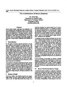
them in a manner which allows reuse or duplication of the original product, its architecture or technology. An intermediate goal may be understanding how a device works to modify or extend functionality in some way. Motivation is often economic since RE can significantly shorten the development cycle and time-to-market of a competing product, and it is this which is likely to have the deepest impact on an embedded systems manufacturer. Clone products and RE-accelerated competition significantly distort market economics, and work to stifle product innovation in the long term. Apart from the economic argument, reasons of security are another major driving force behind RE, however we will not consider national security issues, or traditional cryptographic topics such as side-channel attacks here. We will not even discuss differential power analysis [2] here, apart from noting that it has particular application for embedded systems. Rather we will note that it is neither possible nor desirable to build a completely secure system [3]. However it is possible to consider costs and benefits of securing a system against RE. For many companies developing embedded products, it may be wise to analyse their product design and thus understand the risks of RE as it pertains to them. If necessary they may choose to modify either their hardware design, marketing strategy, or economic forecasts in response to this analysis. The action of hardening an embedded system against RE has cost implications that may include increased development time and effort (including a greater level of development expertise required), increased manufacturing difficulty and thus cost, a more expensive bill of materials (BOM), and reduced serviceability or repair accessibility. Engineers need to be able to understand the big picture behind these issues, and thus need to understand the RE process itself. At this point, it should also be noted that most companies, including nefarious ones, will take a path of least resistance (cost): if design piracy costs significantly less than a new product design, it may be considered. Methods of achieving this piracy could include industrial espionage, network-based attacks to steal designs, insider attacks (often committed by disgruntled employees), head-hunting key staff responsible for the original product design, or the full reverse engineering of the product under attack. Overall, security is only as good as the weakest link. The objective of educating engineers in the field of hardware RE is to ensure that the weakest link is not the embedded system design itself, unless this is the deliberate choice of a manufacturer. III. M ETHOD OF REVERSE ENGINEERING Reverse engineering of embedded systems typically involves several analytical steps. An attack may not necessarily constitute each of these in sequence, but a logical listing sequence will be discussed in the following subsections A to H. As an example to aid discussion, the discussion will continue in relation to a generic un-hardened embedded system with system level diagram as shown in fig. 1. This consists of
Fig. 1.
Block diagram of example embedded system under analysis
a large integrated circuit (IC) connected to volatile memory (SRAM or S/DRAM), non-volatile memory (flash), a fieldprogrammable gate array (FPGA), a user interface of some kind and devices to interface with the outside world. A. Functionality An RE team would be presented with several units, and probably begin by assessing user documentation, repair manuals, product briefs and so on. A list of functionality will also be required for later to double-check that analysis has revealed sufficient hardware and software to provide each identified function. This is relatively simple work, but can be augmented by searching the world wide web for information on newsgroups, blogs, hacking sites and so on. Knowing the manufacturer and any OEM, postings by individuals from these email domains can be tracked and correlated. The example of the Linksys WRT54G, widely documented online, demonstrates the sheer depth and variety of hacking and reverse engineering resources available for specific products [4]. B. Physical structure analysis Dissassembly of the device may be as simple as removing some screws to open a box or as complex as having to work through layers of micromachinery. Considerable time and effort may have been devoted to manufacturability issues by the designers and as such there is likely to be value in understanding this disassembly. Such information may also be found documented in a service manual. Order and location of removed parts should be recorded perhaps most easily accomplished by photography, and ideally by one member of the team dedicated to documenting the process. Any observations and insights of the disassembler should be noted at this stage. Whilst detailed mechanical drawings for replicating enclosures, internal structures and so on can be obtained from static analysis of the parts, assembly drawings need to be made through disassembly followed by reassembly. Analysis of physical structure is unlikely to be an expensive component of the RE, although the reasons behind unusual mechanical arrangements and structures may at first be nonobvious at times.
730
Authorized licensed use limited to: Arizona State University. Downloaded on April 20,2010 at 15:19:13 UTC from IEEE Xplore. Restrictions apply.
C. Bill of materials A bill of materials (BOM) is a list of all components used in the design. Some will be easily identified, but some are difficult to identify. For example, full and semi-custom ICs may not be readily identifiable. Furthermore, the relentless miniaturisation of surface mount devices, particularly diodes and transistors, have resulted in some packages having insufficient surface area for identification marks. Simplified codes may follow the standardised formats from JEDEC, JIS or ProElectron [5] otherwise discrete parts will have to be removed and tested to determine their measurable characteristics. Characteristics can be painstakingly matched to known devices however with tolerances of 5%, it may be necessary to remove and test parts from a number of systems before an accurate determination can be made. Unknown passive parts can be copied: this is a genuine field of research, especially in cases where obsolete parts need to be recreated [6]. In general, solid models from physical measurement can be combined with materials analysis to completely describe many parts such as structural pieces, fixings and passive components. PCB silk screen markings can often provide clues as to the identity of tiny unmarked parts: D101 is probably a diode, Z12 may well be a Zener diode. ICs with unusual or even no markings are more troublesome – if the manufacturer is identified, this may give some clues as to the content. For example some system-on-chip processing cores are more likely to be identified with certain manufacturers than others. A fabrication process may be identified, and this can be tracked down online and related to other known deliveries from that process. Often DMCs use standard off-the-shelf parts, and provide helpful silk screen annotations, kindly assisting in the RE process. The most common difficulty is associated with the use of custom silicon, either from an OEM or from in-house development of large scale integrated (LSI) devices. OEM silicon is often undocumented, but traceable online if not in English, then in Chinese, Korean or Japanese. In house LSI devices may occasionally be offered for sale by a commercialisation arm of the parent company, in which case a feature list will be published somewhere – but documentation may only be provided under non-disclosure agreement (NDA).. Clearly, it is preferable to identify major ICs, but if not, the process does not end there. Analysis can identify exact inputs and outputs and from there infer internal functionality, or the device casing opened and painstakingly analysed silicon layerby-silicon layer. As an indicator of the scale of this process as an industry problem, note that a market survey in 2005 found 186 counterfeit ICs offered for sale [7]. D. System architecture A system architecture analysis reveals a rough block diagram of connectivity and subsystems responsible for various items of functionality. Most important at this stage are identification of power/ground planes and the power distribution to areas of the system. Equally necessary is an identification of
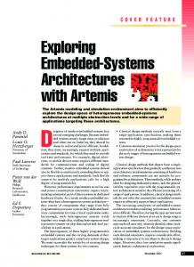
bus connectivity within the system. The presence of a debug port or IEEE 1149.1 can be very significant in assisting the RE process, so any indication of this, such as a set of five test points with pull up resistors located close to the CPU, is an important find. Simple circuit continuity tests and visual inspection of parts and their arrangements can usually be performed and conclusions drawn from this. For example, the same CPU data bus often connects both flash memory and SRAM. Continuity tests can easily reveal if this is true by simply referring to the locations of data bus pins from the device data sheets. Similarly power pins can be examined. This is usually very simple and inexpensive process, but as we shall later, can be complicated substantially by the designers. E. Detailed physical layout Detailed physical layout analysis proceeds from outside in. Where silk screen layout annotations are not present, photography of component placement and orientation can reveal the required information for both outer layers. Next, all components are removed and drilled hole positions noted. As a quick check, the locations of holes on top and bottom can be compared: if these are identical then there are no blind vias and it is unlikely, but not impossible, for there to be buried vias. The PCB is then delaminated (peeled apart layer by layer) and the photography process repeated for each layer from a constant reference position, to build a stack-up of photographically correct layers. These could simply be used to recreate an almost identical PCB. However in practice the composition and thickness of copper and PCB layers must be determined. In practice, a section of the PCB should be found where copper is present on each layer. Most PCBs have a test coupon area designed for this purpose: manufacturing process changes can affect copper thickness in particular, and in turn affect system performance, so manufacturers may need to post-mortem this. To identify PCB layer thicknesses, a multi-layer area is cut-out from the PCB and placed end-on into a hockeypuck shaped mould, which is then filled with epoxy. When set, a lens grinding/polishing machine polishes an end-on section of the PCB which can be examined under a measuring microscope to determine precise thicknesses. A growing number of embedded systems require track impedance control for high speed signals. In this case, the exact characteristics of the PCB are important, including dielectric constant, the prepreg weave thickness and resin type. Impedance can be found through time-domain reflectrometry or using a network analyser. Microscopy can reveal the prepreg type and characteristics. X-rays can be a viable method of extracting layout information, or even provide some useful information on the internals of unknown ICs. For example fig. 2 shows a low-magnification X-ray of a PCB. Rough X-ray photographs such as this can generally be obtained from metallurgy workshops (at a pinch, place the PCB in your carry-on luggage for the cheapest flight
731
Authorized licensed use limited to: Arizona State University. Downloaded on April 20,2010 at 15:19:13 UTC from IEEE Xplore. Restrictions apply.
Fig. 2. X-ray of an FPGA on a 4-layer PCB showing internal structure of the IC, PCB tracks, locations of vias and even the presence of a soldered wire tap near the lower left corner pin of the FPGA. The dark rectangular shadows are surface mount tantalum capacitors in 0603 packages.
you can find and photograph the screen of the X-ray machine as the bag rolls through). Although some specialised equipment is required for this analysis stage, unless impedance control is involved, copying a PCB layout and stackup as-is is certainly neither a difficult nor an expensive task. F. Schematic of electrical connectivity The connectivity check and inspection by X-rays or photographs of a delaminated PCB yields a netlist. This timeconsuming process is at least simple to verify by means such as (a) testing for the expected continuity on the original board, (b) by reference to datasheets giving expected connection for the required functionality, (c) looking for hanging vertices and unexpected shorts, such as a two-pin component with only one pin connected, or both pins of a two-pin component commoned. Netlist to schematic generation is an established area, with commercial tools available to assist in the process [8]. G. Stored program The simplest arrangement in the example embedded system would be both the CPU and the FPGA having individual flash memory storage devices, with parallel and serial connections respectively. However cost factors typically dictate that all non-volatile program storage within a system be clustered into a single device, often flash memory. Storage may include separate boot code and operating code for a CPU, system configuration settings, plus FPGA configuration data. In this subsection we consider determining the location of, and extraction of the stored programs. In the subsequent sections we will look at RE of the firmware/software programs or codes themselves. Mask-programmed gate arrays, non-volatile PLDs and of course ASICs do not require external non-volatile storage, storing their configuration internally. In some cases it is
possible to isolate such a device and read out its internal configuration code. In other cases, where such readout is not possible, or device security measures are in force, the device will need to be either subject to extensive black box analysis or examined internally. The latter can be accomplished through dissolving a plastic case and/or carefully grinding through layers of silicon, reading the state of each stored bit with an electron microscope, or a reflected laser [9]. Undoubtedly, stored program devices with security settings in place are far more troublesome and expensive to RE than the majority systems containing a single non-volatile storage block. The example system in this paper falls into the majority category, so the CPU is responsible for programming the FPGA, and both in turn derive their code from the flash memory. In this case we will also consider the example of a system utilising embedded linux as it’s operating system (such as the original WRT54G), so the flash memory would contain: • Boot code • OS • Filesystem • System configuration settings • FPGA configuration data By contrast a more generic embedded system would contain a monolithic block of boot, OS and applications code stored in flash. Flash memory content can very easily be extracted by either removing the device and dumping it’s content (static analysis), or by tapping off bus signals with a logic analyser during operation (dynamic analysis). The logic analyser method can give useful clues regarding context - for example memory read signals detected immediately following powerup are likely to constitute boot code. However this method obviously only reveals the content of memory addresses that are actually being accessed - the current trace of execution: determining the entirety of stored code in this manner would be next to impossible in most real systems. It would require operating the system in every possible operating mode with every possible combination and timing of input signals in order to guarantee 100% code coverage. Nevertheless, a combination of both techniques is a powerful analytical tool. Jumbled address and data bus lines are common aids to simplify PCB routing even on systems that are not deliberately attempting to obfuscate the interconnections. This needs to be borne in mind with both methods, thus complicating the analysis slightly. Static analysis of the flash memory content first needs to determine the identity of any different areas that may be present. It is simplified if delimiters of erased flash are present, namely long strings of 0xFFFF or 0xFF ending on a block boundary. Detecting such delimiters reveals the separate areas of content between these, which will then need to be identified. Again, the identification process is not particularly difficult - boot code is likely to begin with a vector table and is most likely to reside at the lowest address in flash, or in a specific boot block. An FPGA programming image will be approximately of the size specified in the FPGA data sheet,
732
Authorized licensed use limited to: Arizona State University. Downloaded on April 20,2010 at 15:19:13 UTC from IEEE Xplore. Restrictions apply.
or compressed using a standard algorithm (with a signature that can be searched for). A filesystem will be identifiable through its structure (and on a linux desktop computer the file command is available to rapidly identify the nature of many of these items). The linux kernel, along with other OS kernels, contain distinct signature code and may even contain readable strings (on a linux desktop computer the strings command will find and display these). Where static analysis fails, the combination of static and dynamic analysis is very powerful. For example system configuration data may be stored anywhere in flash memory, and may be difficult to identify by content alone. However simply operating the device and changing a configuration setting will cause a change in memory content. This can be identified either through comparing content before and after, or looking for specific writes to flash memory with a logic analyser. In the extreme case, flash memory can be copied asis and replicated in a copied product. Overall, unless the designers have specifically taken measures to protect their embedded system, the process of reverse engineering nonvolatile memory to reveal stored programs, is relatively simple and inexpensive. H. Software As mentioned, software could be copied as-is without changes. Simple changes could involve rewriting the content of strings to change a manufacturers name, serial number and version codes. Patching legitimate licensed software to counter software copy protection schemes is well established [10]. Items of executable code could also be cut-and-pasted, such as the reuse of an existing bootloader but with different operating software (or more likely, the changing of a filesystem stored in flash to incorporate extra features as in the case of the WRT54G). In contrast to embedded systems hardware RE, software RE of all scales is a very well researched field. Chikofsky and Cross [11] provide an excellent overview, and taxonomy. It is established that at the benign end of the scale, software RE is a useful means to achieve the potential reuse of OO code, whereas at the opposite extreme, circumvention of copy protection schemes leads to software piracy and theft. Interestingly, studies have even considered the morality of software piracy, and attitudes to intellectual property violations, and related this to region [12]. There is no indication that the conclusions are confined to software only. Software plays an important role in embedded systems, and although it is advisable for manufacturers to consider software RE and software security, this will not be considered further here since it is a subset of general software RE and protection [10] [13] [14]. IV. E CONOMIC ANALYSIS An in-house DMC planning to incorporate RE mitigation will be faced with an increase in non-recurring expenditure (NRE) on product development, and probably a small increase in BOM cost. It may enter market slightly later due to
increased development effort. Follow-on impact may include an increase in servicing cost if this is made more difficult, and potentially reduced reliability due to increased complexity. These, collectively, are the negative side of the cost-benefit equation for RE mitigation. However, before forming the equation, it is first necessary to state that an RE attack may be likely, but will rarely be certain (either to take place or to succeed). Foiling this potential attack costs money, but will result in, at best, absolutely no visible benefit. i.e. the best outcome is the lack of competition for a longer time. With no visible outcome, it is thus difficult to ‘sell’ a RE mitigation strategy to any company, and even more difficult to gauge success. It is truly an issue of engineering judgement. In the experience of the author, most DMCs will only engage in a strategy of RE mitigation once they have truly suffered losses from RE-aided competition (assuming they survive the experience). To continue forming the equation, an assessment needs to be made of the ease to RE the product in question, in terms of the RE costs to a nefarious competitor. Then the cost to the DMC of adding several varieties of RE mitigation should be calculated, alongside the increased RE cost and time which would result for the competitor. The increased RE cost adds to the competitors NRE, thus affecting their margins, and the increased pirating time adds to the profitability of the DMC. The measure of success for the DMC is thus to maximise the cost and time taken to RE their product, but at minimum additional NRE and particularly BOM cost to themselves. V. RE MITIGATION TECHNIQUES Since it is not possible to prevent reverse engineering per. se., the issue becomes an economic one: how can embedded system designers maximise the reverse engineering cost experienced by competitors, but at minimal additional cost to themselves. A general presentation of some methods has been provided previously by Grand [15], but here we will specifically consider difficulty of implementation, the cost to a DMC, and the economic impact of implementation. First of all, we define reverse engineering mitigation methods into two classes: passive methods are those that are statically introduced and fixed at design time, as opposed to active methods which resist reverse engineering during an attack. By and large passive methods are less inexpensive to implement by a DMC than active methods. The cost multipliers to the REC come about through three major factors (1) Additional time taken to reverse engineer the system, (2) Greater levels of expertise required to do so and (3) The need for specialised equipment. Following the RE process of section III, the first level of protection can be applied to the functionality assessment. In this case, restricting the release of service manuals and documentation can reduce the degree of information available to an RE team. Manufacturers should control, monitor and ideally limit, information inadvertently provided by employees, especially when posting online. This will undoubtedly increase the time and effort needed to RE a system.
733
Authorized licensed use limited to: Arizona State University. Downloaded on April 20,2010 at 15:19:13 UTC from IEEE Xplore. Restrictions apply.
Physical structure analysis can be made marginally more difficult through the use of tamper-proof fittings for enclosures such as torx and custom screws shapes which would require purchase of specialist equipment. One-way screws and adhesively bonded enclosures work similarly. Fully potting the space around a PCB provides another level of protection. At minimal cost, the primary detraction to the use of these methods comes from any requirement for product serviceability, which would normally necessitate ease of access. Unusual, custom and anonymous parts complicate the RE of a systems BOM. However passive devices can easily be removed and tested in isolation. A missing silk screen causes some difficulty in manufacturing and servicing, but limits the information provided to the RE team. However by far the most effective method of preventing BOM RE is through the use of custom silicon (or silicon that is not available for sale to the RE team). Reverse engineers confronted by a large unmarked IC surrounded by minimal passive components, no silk screen and with no further information would face a very difficult and expensive RE process indeed. The need to identify and/or replicate custom silicon adds significant expense to the RE process, but at great design cost to the DMC: essentially the non-recurring costs associated with custom silicon may be economical only for large production runs. IEEE1149.1 JTAG and other debug ports should be eliminated from semi-custom silicon, and not routed from standard parts to connectors or test pads, and certainly not labelled ’TDI’, ’TDO’, ’TMS’, ’TCK’. For device packages with exposed pins these can still easily be accessed, so BGA (ball grid array) devices are preferred. But even for BGA devices, unrouted JTAG pins can often be accessed by controlled depth drilling through the PCB from the opposite side, meaning that back-to-back BGA placement is most secure (such as a BGA processor on one side of a PCB with a BGA flash memory device directly underneath on the other side). The disadvantage here is that manufacturing cost increases by having doublesided component placement. Double sided BGA placement is yet one step more expensive, but still no guarantee since it is possible, but extremely difficult, to remove a BGA device, reform the solder balls, and then refit this into a carrier which is soldered to the PCB. The intermediate signals through the carrier can then be made available for analysis. Back-to-back BGA packaging generally necessitates blind and/or buried vias, which can increase PCB manufacturing costs - a rule of thumb is by 10% - complicate the layout process and significantly impact on any hardware debugging or modifications needed. It does, however, result in a very compact PCB which might itself be a useful product feature. Similarly, the number of PCB layers would often need to increase to accommodate back-to-back placement, therefore also increasing the RE cost to perform delamination and layerby-layer analysis. Use of X-ray analysis to reveal layout details is difficult if not impossible for multi-layer PCB designs, but can be complicated further by the useful practice of filling all available space on all layers with power plane fills. These can even be crosshatched on internal layers to mask individual
TABLE I PASSIVE METHODS OF INCREASING HARDWARE REVERSE ENGINEERING COST RATED ON SEVERAL CRITERIA , 5= MOST, 0= LEAST
Tamper proof fixtures Potting Remove silk screen Remove component identifiers Use BGA packages Route on inner layers only Use blind/buried vias Jumble buses Route through ASIC Route through FPGA Remove debug port Memory filling
Design cost 2 1 1 1 1 2 2 1 5 2 1 2
RE cost 0 1 1 1 3 2 2 1 3 2 1 2
Manufacturing impact 1 2 1 2 3 3 4 0 2 2 2 0
tracking details on other layers on an X-ray photograph. Electrical connectivity can be difficult to ascertain when devices are operated in an unusual fashion such as jumbled address and data buses. Wiring unused pins to unused pins can add nothing to manufacturing cost, but complicate the RE process. A. Passive obfuscation of stored programs Although this paper does not extend to the much largest research field of software obfuscation methods, there is much that can be performed with little effort to obfuscate the stored code in the flash memory of an embedded system. Firstly, and as mentioned previously, the gaps between code sections (of unerased flash) can very easily be filled with random numbers or dummy code such that detection of separate memory areas is non trivial. Apart from initial boot code, other sections of flash can also be encrypted if execute-from-flash is not required. This will cause difficulties in analysing an image of flash contents, however the unencrpyted boot code may well be small and simple enough to trace and disassemble, revealing an unencrypted entry point to the system, hence the security of such encryption is questionable. Scattering code, data and configuration sections throughout flash memory will cause some programming difficulty but is primarily another means of protecting against stored program analysis. If an FPGA image is stored in flash, simple methods of obfuscating this apart from encryption include performing an exclusive-or on every data byte with some other area of flash, or storing a custom compressed FPGA image (not gzip, zip or methods with identifiable signatures). A summary of various of the discussed RE mitigation methods are shown in table I, where the design cost, effectiveness at increasing RE cost, and manufacturing impact are identified using a five point subjective scaling for the example embedded system. B. Programmable logic families SRAM based FPGAs normally require a configuration bitstream to be provided from an external device - such as a
734
Authorized licensed use limited to: Arizona State University. Downloaded on April 20,2010 at 15:19:13 UTC from IEEE Xplore. Restrictions apply.
serial flash configurator, or provided by a microprocessor, such as the case in the example system. Since this bitstream can be accessed physically with little difficulty, this firmware can always be copied by tapping off and replicating the bitstream. EEPROM based programmable logic devices (PLDs) and even the obsolete EPROM versions and newer flash based products, are more secure since the configuration program resides internally and does not need to be transferred to the device following reset. Note that some flash-containing devices encapsulate two silicon dies in one chip - a memory die and a logic die, and thus are less secure since the configuration bitstream can always be tapped once the encapsulation is removed. Some devices provide a security setting to prevent readout of a programmed bitstream from the external programming pins. Use of this feature is highly recommended. In a regular cell-structure device such as a maskprogrammed gate array (MPGA), the location of memory configuration elements is known, determined by the manufacturer for all devices in that class. Using the methods discussed in section III-G, it is possible to retrieve configuration information using sophisticated but available technology. A full-custom ASIC can be reverse engineered by analysing silicon layer-by-layer (similar to the PCB delamination, but with layers revealed through careful grinding), but even this technique can be complicated through countermeasures such as inserting mesh overlay layers [16]. Antifuse FPGAs are considered the most secure of the standard programmable logic devices [17] [7], due to the location of fuses buried deep below layers of silicon routing, rather than being exposed near the surface. It is not impossible to RE systems incorporating ASICs or secured antifuse FPGAs, but this does require significant levels of expertise, requires the use of expensive specialised equipment and is time consuming. C. Active RE mitigation Many passive RE mitigations have active variants: electrical connectivity can be confused by using spare inputs and outputs from processors to route signals which are not timing critical but which are functionally critical. Dynamically jumbled buses provide one further level of complication over static jumbling, but add the cost of incorporating active devices to perform the jumbling/de-jumbling. ASICs are probably the ultimate tool in mitigating RE attempts, but even the humble FPGA can be quite effective: IP cores are not easy to identify or isolate, and if using external memory, can access this any way: linearly, non-linearly or using encryption. A core which is completely custom [18] and company confidential, through hiding details of its instruction set architecture, increases security further. Table II shows the relative strengths of several classes of active protection when implemented with static and dynamic algorithms respectively. The three classes are defined as follows: Information hiding uses existing resources to attempt to conceal information from an attacker. This may involve combining
TABLE II R ELATIVE STRENGTH OF ACTIVE PROTECTION METHODS , 5= MOST, 0= LEAST
Information hiding Obfuscation Deliberate confusion
Fixed timing 0 1 4
Dynamic timing 2 3 5
code and data by such methods as concealing operating software within data arrays, or by sharing information across data reads in a non-obvious fashion. At a hardware level, this may also include operating electronics at marginal voltage levels, relying upon unusual signalling or data handling schemes. Obfuscation, normally a passive method (such as swapping the names of labels and functions within code, or jumbling the PCB silk screen annotations) can also be active in arrangements such as those that change bus connectivity [19] [20], or device pin usage (for example multiplexing pins). Each uses existing resources in ways specifically designed to complicate the RE process. Protection by confusion adds resources to deliberately mislead an attacking RE team. This could include large pseudorandom data transfers, out-of-order code reading [21] and so on. There may be signal interconnections that employ current signalling but overlay a randomly modulated voltage signal upon the wire, or perhaps a meaningful signal driving a redundant signal wire. Spatial methods operate at a placement or connectivity level, such as scrambling bus order depending upon memory address, turning on or off signal path routing devices in a non-obvious fashion or similar. Temporal methods confuse through altering the sequence and/or timing of events. In general, temporal methods are likely to cost more to develop, debug and test, and also increase both manufacturing and probably servicing costs, than fixed timing methods. Both information hiding and obfuscation could well be of similar development cost - mostly adding to NRE, however deliberate confusion methods will undoubtedly cost more to develop than either hiding or obfuscation, and will increase manufacturing cost. What is clear is that custom silicon, implementing active confusion and protection means, provides the greatest degree of protection. A DMC concerned by the costs involved in creating a full-custom ASIC for security purposes, could use this for a range of products. For the REC, the active protection methods in each category, particularly the dynamic timing cases, will require employing a highly skilled and flexible RE team with access to specialised equipment. VI. A N MS C LEVEL REVERSE ENGINEERING EDUCATION Within Nanyang Technological University School of Computer Engineering, RE is taught as part of the MSc programme in Embedded Systems. It comprises 50% of the ES6190 Secure Embedded Systems subject (which works out to 6 three-hour
735
Authorized licensed use limited to: Arizona State University. Downloaded on April 20,2010 at 15:19:13 UTC from IEEE Xplore. Restrictions apply.
evening classes/laboratory sessions and perhaps 15 hours of self-study). The RE curriculum covers the major elements presented in this paper, namely understanding the risks embodied by nefarious RE, understanding the process of RE, understanding the options to protect an embedded system against RE and an open-ended consideration of both active and passive countermeasures. This is taught through 4 three-hour lecture sessions. One three-hour laboratory session is provided (with an option to combine with home study), in which students trace through a national security scenario in which a hostile foreign power has planted network-attached-devices of an unknown nature throughout the Internet infrastructure of a country. For time reasons, the hardware RE process has been completed prior to the laboratory session, so that on the day students are presented with dumps of non-volatile memory storage, and some unknown hardware specifications. By following the taught RE process, and often accompanied by displays of considerable ingenuity, students are able to identify bootloader, operating system code, an FPGA image, and a filesystem. They hack into each of these to reveal further information on the hardware itself and upon the (simulated) attacks that this device can launch upon the Internet in their country. This highly popular laboratory session is conducted on PCs running Kubuntu 7.10 Linux with a full complement of open source debugging and analysis tools Finally, students are presented with group projects for further research. These culminate in 30-minute seminars presented to the entire class (followed by lively question sessions), and a journal-paper style report. Typical projects are case studies of actual RE attacks resulting in product piracy, indepth surveys of one or more protection methods, and impact assessments on different industries. Overall assessment is by 2-hour examination (40%), project grading (30%), laboratory session (25%) and one or more homework quizzes (5%). VII. C ONCLUSION This paper has overviewed the topic of the RE of embedded systems, identifying a typical RE approach. It has discussed and classified many mitigation strategies, and presented an economic argument for the prevention of RE. In particular it has related this to the education of students in an embedded systems MSc course, to attempt to both raise awareness of the issue, and to prepare such students for efforts in industry to counter the persistent threat of RE. It is an unfortunate fact that the engineering answer to this product piracy risk, incorporating RE protection, leads to lower profits all around. Socially speaking this could be considered a lose-lose situation. However it does lead to the gainful employment of more engineers, especially those skilled in the analysis and methods of RE and its mitigation. RE will probably always be a factor in electronic design, and can be applied for social good as well as for nefarious purposes. This can be for reasons of national security or
private interest in either case. Over this backdrop, smaller manufacturers struggling to succeed in a crowded marketplace should make an informed decision regarding what degree and type of RE protection, if any, they choose to apply. This paper attempts to move some way towards informing that decision, both as a survey paper and by presenting an appropriate educational curriculum structure. R EFERENCES [1] T. J. Biggerstaff, “Design recovery for maintenance and reuse,” in Computer, July 1989, pp. 36–49. [2] P. Kocher, J. Jaffe, and B. Jun, Differential Power Analysis, ser. Lecture Notes in Computer Science, M. Wiener, Ed. Berlin, Germany: Springer, 1999. [3] W. Diffie and M. Hellman, “New directions in cryptography,” IEEE Trans. Information Theory, vol. 22, pp. 644–654, Nov. 1976. [4] (2006, Dec.) Linksys WRT54G and WRT54GS hacking. [Online]. Available: http://www.i-hacked.com/content/view/26/42/ [5] (2007, May) Reading transistor markings. [Online]. Available: http://www.elexp.com/t tranmk.htm [6] T. Waggoner, “Exporting solid models into finite element analysis (FEA) for reverse engineering of electrical components,” in Electrical Insulation Conference and Electrical Manufacturing Expo, 2005. Proceedings, Oct. 2005, pp. 231–235. [7] T. Barraza. (2005, Aug.) How to protect intellectual property in FPGA devices. [Online]. Available: http://www.eetimes.com/showArticle.jhtml?articleID=170000386 [8] B. N. Naveen and K. S. Raghunathan, “An automatic netlist-to-schematic generator,” IEEE Des. Test, vol. 10, no. 1, pp. 36–41, 1993. [9] D. Samyde, S. Skorobogatov, R. Anderson, and J.-J. Quisquater, “On a new way to read data from memory,” in SISW02: Proceedings of the First International IEEE Security in Storage Workshop. IEEE Computer Society, 2002, p. 65. [10] C. S. Collberg and C. Thomborson, “Watermarking, tamper-proofing, and obfuscation - tools for software protection,” in IEEE Trans. Software Engineering, vol. 28, no. 8, Aug. 2002, pp. 735–746. [11] E. J. Chikofsky and J. H. Cross, “Reverse engineering and design recovery: A taxonomy,” in IEEE Software, Jan. 1990, pp. 13–17. [12] W. R. Swinyard, H. Rinne, and A. K. Kau, “The morality of software piracy: A cross-cultural analysis,” in Journal of Business Ethics, vol. 9, no. 8, Aug. 1990, pp. 655–664. [13] G. Naumovich and N. Memon, “Preventing piracy, reverse engineering, and tampering,” Computer, vol. 36, no. 7, pp. 64–71, 2003. [14] D. Hwang, P. Schaumont, K. Tiri, and I. Verbauwhede, “Securing embedded systems,” IEEE Security & Privacy, vol. 4, no. 2, pp. 40– 49, 2006. [15] J. Grand, “Practical secure hardware design for embedded systems,” in Embedded Systems Conference, California, Apr. 2004. [16] O. Kommerling and M. Kuhn, “Design principles for tamper-resistant smartcard processors,” in Proc. Workshop on Smartcard Technology. USENIX, May 1999, p. 65. [17] T. Kean, Secure configuration of Field Programmable Gate Arrays, ser. Lecture Notes in Computer Science. Berlin, Germany: Springer, 2001, vol. 2147. [18] R. Shadich and I. V. McLoughlin, “A modular computational engine for communications processing,” in Australian Telecomms. and Networking Apps. Conference, Melbourne, Australia, Dec. 2003. [19] Y. Yu, J. Leiwo, and B. Premkumar, “Hiding circuit topology from unbounded reverse engineers,” in Lecture Notes in Computer Science, 2006, pp. 171–182. [20] E. Hannah, “Method and apparatus for conditionally obfuscating bus communications,” USA Patent PCT/US2005/040 371, Nov. 4, 2005. [21] X. Zhuang, T. Zhang, H.-H. Lee, and S. Pande, “Hardware assisted control flow obfuscation for embedded processors,” in Proc. 2004 Int. Conf. on Compilers, Architectures, Synthesis on Embedded Systems, 2004, pp. 292–302.
736
Authorized licensed use limited to: Arizona State University. Downloaded on April 20,2010 at 15:19:13 UTC from IEEE Xplore. Restrictions apply.