CiiT International Journal of Networking and Communication Engineering, Vol 4, No 7, June 2012
377
Secure Low Cost FPGA-based AMI System using LTE Technology M.M. Abutaleb and A.M. Allam
Abstract---The smart grid is seen as the greatest technological invention—in the context of energy supply—since the grid connection of millions of households. Household smart meters that measure power consumption in real-time at fine granularities are the foundation of a future smart electricity grid. As smart meters are spreading into more and more households, electricity customers are directly affected by the technology. However, the widespread deployment of smart meters has serious privacy implications since they inadvertently leak detailed information about household activities.This paper presents the design and implementation of a secure low cost FPGA-based prototype for smart meter in automatic meter infrastructure (AMI) system that precisely measures the use of residential energy and instantaneously transmits the reading to concentrator using 3GPP Long Term Evolution (LTE) technology. Also, we explore the feasibility of designing physical-layer privacy-preserving smart meters using direct sequence spread spectrum. The proposed smart meter consists of three main parts: Accurate digital meter, encryption scheme and transmission facility. Keywords---AMI, Electrical Energy, Smart Meter, FPGA, DSSS, LTE.
I.
INTRODUCTION
T
HE electrical distribution grid is transitioning from the traditional grid into the new so-called smart grid, partly to become more exible and to be able to accommodate large energy production from renewable sources. This transition involves, among other steps, the installation of advanced equipment in places where previously it was not found, such as the distribution section of the electric network. The most important change in the distribution part of the electrical network is the introduction of smart meters replacing the traditional domestic electrical meters. Advance Metering Infrastructure (AMI) is one of the basic functional blocks of the Smart Grid. It is a system that supports two-way communications with customers and electric company [1]. AMI comprises of components such as the AMI meter, AMI head-end, Meter Data Management System (MDMS), the communication network, the access points, and the endpoints. The AMI systems make use of smart meters, and In-home displays to assist in the determination of the usage pattern and make efficient allocation of resources wherever required. However, increasing usage in Smart Grid services bear huge Manuscript received on May 05, 2012, review completed on May 17, 2012 and revised on May 21, 2012. M.M. Abutaleb is with the Department of Electronics, Communications and Computer, Faculty of Engineering, Helwan University, Cairo, Egypt. E-Mail:
[email protected] A.M. Allam is with the Department of Electronics, Communications and Computer, Faculty of Engineering, Helwan University, Cairo, Egypt. E-Mail:
[email protected] Digital Object Identifier No: NCE062012004.
0974-9713/CIIT–IJ-3376/07/$20/$100 © 2012 CiiT
risks at various points and AMI is one such area that can be exploited by launching malicious attacks that could threaten the mission of the Smart Grid Services [2]. Conventional electricity meter namely electromechanical meters are passive meters offering very little information on electricity usage, pattern, or any other information that can be used to improve on energy usage, billing and energy conservation. Electronic energy meters had already surpassed the electromechanical energy meter nowadays because in addition to measuring energy used, they can also record other parameters such as maximum demand and RMS calculations which show real-time data useful for balancing electric loads and reducing power outages. In today‘s market, electronic designs are getting more complex and precise. Technology such as Field-programmable gate array (FPGA) is introduced into the market to create more options for developers. Now, applications of FPGAs include digital signal processing, aerospace and defense systems, ASIC prototyping, cryptography, radio astronomy and a growing range of other areas. This in turn creates more challenges in making a cheaper and better smart energy meter using FPGA. The purpose of this work is to develop and implement a general purpose VLSI (Very Large Scale Integration) Test Module based on a FPGA system to model an AC single-phase smart energy meter that can serve as an ‗in line‘ replacement for the meters currently in use, while already implementing the new technology. The proposed meter is connected between the AC main supply and the load (electrical appliances) to measure real power supplied to the load and displays the energy usage in a LCD. These readings are able to send to remote areas using LTE technology which enables the meter to perform SSM (supply side management) in the form of forced non-essential load disconnection and upload the energy usage to a database without the need for physical meter reading. Therefore relays are installed into the circuitry which serves as feedback system function to regulate power consumption. The feedback system serves the purpose for the smart characteristic of this prototype meter. In this paper, we also consider a different approach for privacy transmission which is called spread spectrum. Spread spectrum is a kind of modulation that spreads data transmission over available frequency band, in excess of minimum bandwidth required to send the information. The spreading makes signal resistive to noise and other interference. The technique has many unique properties such as the ability to eliminate multi-path interference, communication privacy, multi-user handling capacity over a single frequency, low power spectral density since signal is spread over a large frequency band [3].
Published by the Coimbatore Institute of Information Technology
CiiT International Journal of Networking and Communication Engineering, Vol 4, No 7, June 2012 3GPP Long Term Evolution (LTE), the latest mobile communication network, is a promising option for a smart grid [4, 5]. LTE was developed to fulfill mobile users‘ demands for higher data rates and stabler service performance. 3GPP white paper and LTE service operators announced that the main advantages with LTE are to provide high throughput (up to 300 Mbps in downlink, and 75 Mbps in uplink), low latency (less than 50 ms for control plane latency, and less than 5 ms for user plane latency), plug and play, Frequency (FDD) and Time Division Duplex (TDD) in the same platform, an improved end-user experience and a simple architecture resulting in low operating costs [4]. However, to the best of our knowledge, there is no use of FPGA-based and direct sequence spread spectrum for smart meter implementation and data privacy so far. The organization of the paper is as follows. The next section discusses the related works in this field. Section III describes the system model which will be discussed in the paper. Section IV presents the design flow of the suggested smart meter and experimental results of designed meter. In section V a suggested method which provides privacy without overhead in computation level or transmission bandwidth. Section VI, LTE technology is suggested to be a good choose which fulfill the meter transmission requirement and final we give conclusion to the paper.
378
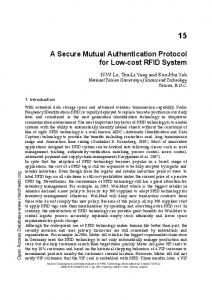
III. SYSTEM MODEL In this section, we present our conceptual model. A smart meter provides the separation between intra- and inter-network communications. An intra-network (i.e., home area network) consists of communications among household devices whereas an inter-network (i.e., wide area network) consists of communications among households, utilities, and system operators. As shown in figure 1, the system consists of three main components: Smart meter: equipment that measures the power consumption by user and sends it to concentrator via wireless channel. Concentrator: equipment that aggregates the data of multiple smart meters and sends it to metering data management system. Metering data management system (MDMS): The MDMS is responsible for aggregating, validating and permitting editing of meter data. It stores the data before it is goes to the dedicated storage facilities.
II. RELATED WORKS In order to overcome the problems of the traditional meter reading system, efforts are underway around the world to automate meter reading and to provide comprehensive information to the consumer for efficient use of the utilities [6-11]. Researchers proposed different implementation techniques. In [6] short message service (SMS)- based reconfigurable automatic meter readingsystem is introduced. The work uses the GSM network to send automatic meter reading data. In [12] a secure and scalable automated meter reading is introduced. The work uses existing local ISPs instead of requiring its own set of proprietary communication infrastructure. The gateway node basically consists of an embedded microprocessor system, based on embedded Linux, and a modem. In [13] remote real time automatic meter reading system that employs distributed structure based on wireless sensor networks, which consists of measure meters, sensor nodes, data collectors, server and wireless communication network. Similar work is introduced in [14] and [15]. These systems consist of measure meters, sensor nodes, data collector (gateway), management centre (server) and wireless communication networks based on ZigBee communication technology. In [16]the design and implementation of a secure low cost automatic meter reading (AMR) system is presented to measure and transmit the total electrical energy consumption to main server using general packet radio service (GPRS) technology provided by GSM networks.
0974-9713/CIIT–IJ-3376/07/$20/$100 © 2012 CiiT
Fig. 1. System Components
IV. DESIGN FLOW Today, almost every VLSI design team applies programmable logic devices [17] to facilitate the overall design process and to minimize the final cost. Fast reconfigurable logic together with high rate analog-to-digital converter (ADC) opens this area for digital data processing and control. The on-site data processing in FPGA-based systems minimizes the risk of faulty transmission of analog measured data [18]. Basically the energy meter measure the instantaneous voltage (volts) and current (amperes) and finding the product of these to give instantaneous electrical power (watts) which is then integrated against time to give energy used in kWh - kilo watt hours. This is achieved by using the Xilinx Spartan 3E FPGA toolkit [19] which provides on-board devices: FPGA chip XC3S500E, LTC6912-1 dual-channel programmable gain amplifier (PGA), Linear Technology LTC1407A-1 dual channel 14-bit analog-to-digital converter (ADC), and a 2-lines/16-characters liquid crystal display (LCD). Fig.2 presents the design flow of the proposed meter system. There are two main components in this meter design, Analog Capture Circuit and Energy Capture Circuit. The power from the
Published by the Coimbatore Institute of Information Technology
CiiT International Journal of Networking and Communication Engineering, Vol 4, No 7, June 2012 distribution substationis connected in a similar fashion as the input side of any residential energy meter.
379
the effect that the current measurement needs to be accurate over a dynamic range of 1600:1. Because AC signals are usually offset to half of the sampling range when sampling with an ADC, this dynamic range of 1600:1 requires an ADC with at least 3200 increments. This can only be achieved by ADC‘s with 12-bit, ideally 14-bit. The LTC1407A-1 is a 14-bit two‘s complement, 3Msps ADC with two 1.5Msps simultaneously sampled differential inputs, suitable for high speed, portable applications. The analog capture circuit converts the analog voltage on VINA or VINB and transform it to a 14-bit digital code D[13:0], as expressed by the eq.1.
whereK and G are the scaling factor of transducer and the gain of amplifier, respectively. The chosen gain in this work is 1 as it offers the widest range of input voltage range. The reference voltage VREF is 1.65V, generated via a voltage divider as shown in Fig.3. Fig. 2. Block diagram of proposed System
A. Analog Capture Circuit The power line is monitored by Analog Capture Circuit by means of voltage and current transducers. The proposed meter has two analog input channels which are known as the current sensing and voltage sensing channels. The PGA, whose gain can be controlled, is used in each of sensing channel to allow easy transducer interfacing. As the load is connected to a high nominal main of 220V AC rms, both channels required a current and voltage transducers to sense the high load voltage and current. The maximum differential voltage input signal for each channel is ±500 mV. Scaled analog signals will be converted into a digital signal by the ADCs. The analog circuit (Fig.3) consists of a Linear Technology low noise, digitally programmable gain pre-amplifier LTC6912-1 that scales the incoming analog signal from the sensor output with a chosen gain, followed by LTC1407A-1 analog-to-digital converter.
Fig. 3. Detailed View of Analog Part
If the class I accuracy is considered thoroughly, the measurement of instantaneous power should be accurate within 1% for 0.1I which is a tenth of the calibration current. This has
0974-9713/CIIT–IJ-3376/07/$20/$100 © 2012 CiiT
B. Energy Capture Circuit The ADC converts input signals of two channels to 34 bits digital signal at a sampling rate of 700 kHz. The 14 bits signal is serially transferred to FPGA later. The Reading Unit captures the ADC digital data and performs calculations to find the actual value of VINA and VINB (current and voltage samples). The formula is as below:
The KWH Capture uses these values to generate pulses proportional to the amount of energy consumed by load. Track of the number of samples (N) that are present in 1 second (frame) is kept and used to obtain the RMS values for current and voltage.
Power and energy are calculated for a frame of active energy samples. These samples are phase corrected and passed on to the process that uses the number of samples and use the formulae listed below to calculate total active power.
The consumed energy is then calculated based on the active power value by calculating the average power for each frame to generate the energy pulses. This is equivalent to converting it to energy. After the accumulated energy crosses a threshold, a pulse is generated. The amount of energy above this threshold is stored, and new energy amount is added to it in the next frame. Because the average power tends to be a stable value, this way of generating energy pulses are very steady and free of jitter. The threshold determines the energy tick specified by the power company and is a constant, for example, it can be in kWh. In most meters, the pulses per kWh decide this energy tick. For example, in this design, the number of pulses generated per kWh is set to 100for active energies. The energy tick in this case is 1 kWh/100. Energy pulses are generated and
Published by the Coimbatore Institute of Information Technology
CiiT International Journal of Networking and Communication Engineering, Vol 4, No 7, June 2012 also indicated via LED on the board. The average power is in units of 0.01 W and 1 kWh threshold is defined as: 1 kWh threshold = 1/0.01 × 1 kW × (N/sec) × (sec/hour) = 100×1000×700000×3600 = 2.52x10 14 (5) The Control Unit performs all of the control tasks such as controlling the PGA and ADC, counting energy pulses using KWH Counter, driving the LCD using BCD Decoder, generating secure data using Direct Sequence Spread Spectrum Technique (DSSS) and communicating with the LTE module in such a manner that none of these functions are compromised. It is furthermore also responsible for controlling the relays based on the received control signals from the control center. A 24-bit KWH Counter is connected to the frequency output of KWH Capture to accumulate the pulses over time. It counts these energy pulses in order to display the reading of the energy accumulated data for the user. As the LCD only recognize BCD data format, it needs to perform 24-bit binary to BCD conversion which is done in BCD Decoder. Once the data is decoded, it sends 8 bits data to LCD in parallel. C. Experimental Results This section discusses the simulation and testing of the proposed system. The simulation result of the timing diagram of input module (ADC) and output module (Binary to Decimal) is illustrated. The timing diagram analysis in Fig. 5 shows that each SPI_SCK period takes a total time of 120 ns. For SPI_MOSI state HIGH, it takes 100 ns. The main component that controlled the whole process is the 50 MHz clock.
380
Fig.7. Result of KWH Calculation
The binary to decimal conversion simulation is illustrated in Fig.8. The signal ‗start‘ will begin the conversion of binary input ‗bin‘ by performing the shifting when HIGH and store in BCD shift register. The decimal data will be updated after the last bit shifting when signal ‗done_tick‘ trigger HIGH.
Fig.8. Result of BCD Operation
The above simulation show that the system is functioning well.In regard to the designated hardware realization, the VHDL code is synthesized by considering Spartan-3E Xilinx chip XC3S500E. Design is synthesized with Xilinx Synthesize Tool (XST), here we conclude that the total critical path delay is 8.790ns and the total circuit area is 230 slices with 4% utilization.The result of the capture energy consumption by FPGA is shown in Fig. 9.
Fig.5. Result of Amplifier Communication
Signal ADC_CONV bits in Fig. 6 are used to test out the functionality of the VHDL code. The signals SPI_SCK take 40 ns per cycle before transition and store in ‗AdcVinA_temp‘ and ‗AdcVinB_temp‘ when SPI_SCK state LOW. Once the conversion process is done, data stored in ‗AdcVinA_temp‘ and ‗AdcVinB_temp‘ are transferred to ‗AdcVinA‘ and ‗AdcVinB‘. The function of the sample is to specify the completion of the entire cycle of ADC conversion process and prepare for new ADC data transition. The timing of the entire process of ADC conversion takes 1400 ns per cycle and sampling rate of 700 KHz.
Fig. 9. Display Result of Measurements
Upon our Knowledge, it is the first time to design an AMI smart meter using FPGA technology. V. SYSTEM SECURITY The suggested added module in the Control Unit of meter will be just an addition module 2 with pseudo random generator as shown in Fig. 10. This addition is low cost and provides privacy on signal without any extra computation load as in ordinary cryptographic techniques, which provide high speed encryption due to its operation in physical layer.
Fig.6. Result of ADC Communication
The timing diagram analysis in Fig.7 shows the KWH calculation. It starts operation with ‗edge_start‘ simulation. Signal ‗kwh_pulse‘ state HIGH trigger edge and ‗kwh_value‘ outputsthe calculated value of energywhwn one second reach.
0974-9713/CIIT–IJ-3376/07/$20/$100 © 2012 CiiT
Fig. 10. Block diagram of proposed System.
Published by the Coimbatore Institute of Information Technology
CiiT International Journal of Networking and Communication Engineering, Vol 4, No 7, June 2012 We assume that the data from electrical meter is binary uni-polar Non-return to zero uniform distribution sequence and there is synchronization between the pseudo random generator in meter and that at concentrator. Consider a binary discrete-time communication system with the received signal a time sequence at the concentrator defined by: (6) where is the sending signal a time sequence from smart meter of single user, and is additive zero-mean white Gaussian noise (AWGN), (7) where is the sequence of information symbols (antipodal binary, ), which represent the power consumption of customer measured by electrical meter section in smart meter and is PN code sequence.Of course each smart meter at neighbor area has its own sequence, which provides the authentication for each reading. In equation (7), we consider modulating each symbol with another {0,1}-valued sequence (a spreading sequence generated from pseudo-random generator) such that each symbol results in the transmission of either or its compliments; depending on the value of . The spreaded data is independent to PN code and source data , due to the nature of PN code which is noise like spectrum and the properties of code [3]. Thus each bit of duration T is coded into a sequence of N chips of duration : The increase in signaling rate spreads the spectrum of the transmitted signal by a factor of N.As shown the reading sequence is masked by code which plays the key role in encryption algorithm, the concentrator can only reconstruct the if it has the same code sequence, which is dispreading process. From the above introduced technique, we can map the spreading technique terminology into the encryption technique terminology, so let be the space of plaintext which is the reading of power consumption of customer read by smart meter, i.e. . be space of ciphertext send by smart meter to concentrator, i.e. . be space of keys or PN code assigned for each user used in spreading the data source, i.e. . Now we need to analyze the performance of the introduced technique to provide the privacy of user's data transmitted over last mile, by using information theory and measure the average information about key or code gained by eavesdropper from intercepting the transmitted spreaded data. Also, measure the amount of spreaded data intercepted before the eavesdropper can know the code. A. Performance Analysis for Suggested Scheme In this section we use information theory to evaluate the performance of the suggested cryptosystem by measuring key equivocation and unicity distance of suggested cryptosystem.
0974-9713/CIIT–IJ-3376/07/$20/$100 © 2012 CiiT
381
Definition1. Key Equivocation: The amount of uncertainty of the key (code), when the ciphertext (spreaded data) is known . Theorem 1. Let be a cryptosystem. Then, Proof. Based on the definition of conditional entropy:
Similarly So
Since So To maximize the uncertainty of an adversary in determining key we must maximize the conditional entropy . But with equality holding only when , are independent. For this to happen , i.e average information of source data is equal to average information of spreaded data, which is valid for this cryptosystem because each bit in source data is modulated to N sequence bit code. Definition 2. The unicity distance of a cryptosystem is defined to be the value for which the average amount of ciphertext required to uniquely define the key, given sufficient computation time. Theorem 2. Let be a cryptosystem. Then,
Proof. Since
Since
So
If the input information has a uniform distribution so unicity distance tends to infinity. We now show how the information leakage to eavesdropper from transmitted signal depends on the probability distribution of the data source, which is obviously uniform distribution if use any line coding technique. The point is that the uniform distribution of data source from meter and the spreading process that were constructed at the smart meter can achieve unicity distance tends to infinity. VI. TRANSMISSION FACILITY There are many different forms of communication links that can be utilized as the communication medium in an AMI system [20]. The latest wireless network, 3GPP Long Term Evolution (LTE), is considered to be a promising solution for
Published by the Coimbatore Institute of Information Technology
CiiT International Journal of Networking and Communication Engineering, Vol 4, No 7, June 2012 smart grids because it provides both low latency and large bandwidth. In this paper, the specific requirements imposed by an advanced meter infrastructure on the LTE communication infrastructure are determined. AMI collects information of consumption records, alarms and status from customers and impose consumptions of customers. Based on its two-way communication and consumption metering, AMI enables real time pricing and peak shaving in a smart grid. Referring to Wide-Area Measurement System (WAMS), latency less than 1 second (typically 100~200 ms) is required to achieve real time pricing requirements [21, 22]. Generally speaking, AMI needs to report consumption status at a rate of 4 ~ 6 times per hour, that is, each consumption measurement is sent every 10 ~ 15 minutes. There are four different message types for an AMI outputs: Data, Configuration, Header, and Out-Command; one In-Command message for its input as shown in standard IEC [23-25].We use 24 bits for representing the meter reading in data information, 8 bits for each device status, and 20 bytes for basic identification information (including AMI ID, time date stamp, checksum and so on) in each type of message. In [16] the meter ID and its reading (KWH) are sent to a central server using general packet radio service (GPRS) technology. GRPS is the technology used the GSM network to connect mobile to the Internet. A comparison can be done between GPRS and LTE (Table I) to show that the last is better to provide the communication requirements needed for AMI. TABLE I COMPARISON BETWEEN GPRS AND LTE GPRS LTE Downstream 28 Kbps 300 Mbps rate Upstream 56 Kbps 75 Mbps rate 5 ms for user >1s Latency plane
deployed to model a smart energy meter. This prototype measurement system shows a very good accuracy, quite simple and cost-effective structure. In this paper, a direct sequence spread spectrum technique has been used to provide the privacy on transmitted data in AMI-meter. The proposed technique is mainly based on the well-known spread spectrum technique. The developed technique has been introduced to the link between smart meter and concentrator. The proposed technique has shown its ability to provide privacy on the grid without imposing extra processing or bandwidth costs and also, without any information gain about PN code if the average of information for both source data and spreaded data is equal and the statistical distribution of source data is uniform. REFERENCES [1]
[2]
[3]
[4] [5]
[6]
[7]
[8]
As shown in Table I, the comparison is bias for LTE the 4th generation than GPRS the 2.5 generation, from view point of peak rate can be supported and the latency criteria that can fulfill the communication requirements of AMI must be for it. For AMIs whose latency deadline is 1 second, data message length is 100 bytes and sent every 15 minutes. LTE are provide high throughput (up to 300 Mbps in downlink, and 75 Mbps in uplink), this result is calculated to be 75 Mbps × 1 second= 75 Mbits ≈ 7.5 MB, which means LTE can accommodate up to 75,000 AMIs communication in uplink even in the worst case. So, this show that LTE is good candidate for AMI from view point of scalability of infrastructure plus it fulfills the communication requirement for AMI.
[9] [10] [11] [12] [13]
[14]
[15]
VII. CONCLUSIONS
[16]
The design and Implementation of secure and low-cost wireless AMI-meter using LTE technology has been presented. The AMI-meter system consists of a smart meter and a LTE based transmitter. The design and validation of a VLSI Test Module based on the FPGA system is described that can be
[17]
0974-9713/CIIT–IJ-3376/07/$20/$100 © 2012 CiiT
382
I. Yang, N. Jung and Y. Kim, Status of Advanced Metering Infrastructure development in Korea, in Proceedings of Transmission & Distribution Conference & Exposition, Daejeon, South Korea, Oct. 26-30, 2009. D.G. Hart, Using AMI to realize the Smart Grid, in Proceedings of the Conference on Power and Energy Society General Meeting - Conversion and Delivery of Electrical Energy in the 21st Century, Pittsburgh, PA, July 20-24, 2008. Md. Al Mamun, Md. Hossain, Md. ZahangirAlam, Md. Zaman, Ahmmed, Kanij T., Performance evaluation of Pseudo-Code of Multiuser environment CDMA Technology, IEEE International Conference, Vol. 21, Issue-23, pp-1887-1892, 2007. S. Sesia, I. Toufik, and M. Baker, LTE: The UMTS Long Term Evolution from theory to practice. John Wiley & Sons Ltd., 2009. P. Lescuyer and T. Lucidarme, Evolved Packet System (EPS): The LTE and the SAE Evolution of 3G UMTS. John Wiley & Sons Ltd., January 2008. A. Abdollahi, M. Dehghani, and N. Zamanzadeh , ―SMS-based reconfigurable automatic meter reading system,‖ IEEE International Conference on Control Applications (CCA 2007), pp. 1103 – 1107, Oct, 2007. C. Brasek, ―Urban utilities warm up to the idea of wireless meter reading,‖ The IEE Computing and Control Engineering, Vol. 15, No. 6, pp. 10-14, December/January 2004/05. M. Baker, ―Added value services through the use of amr in commercial and industrial accounts‖, Conference on Metering and Tariffs for Energy Supply, pp. 210-212, 25-28 May 1999. M. Venables, ―Smart meters make smart consumers,‖ IET Engineering and Technology, Vol. 2, No. 4, p.23, April 2007. Wikipedia Page (7/4/2012) [Online] available: http://en.wikipedia.org/wiki/Automatic_meter_reading T. Whittaker, ―Final word,‖ IET Control and Automation, Vol. 18, No.3, p. 48, June/July 2007. P. Palensky and Ge. Pratl, ―Secure and scalable automated meter reading,‖ Domestic Use of Energy Conference, pp. 233-236, 2003. L. Cao, J. Tian, and Y. Liu ―Remote real time automatic meter reading system based on wireless sensor networks,‖ 3rd International Conference on Innovative Computing Information and Control, 2008 (ICICIC '08), Dalian, Liaoning, pp. 591 – 591, August 2008. G. Álvarez, H. Cepeda, I. Laniella, N. Benítez, and C. Amuchástegui, ―Embedded system for a wireless automatic meter reading management,‖ IADIS International Conference of Applied Computing 2007, pp. 777-780, 2007. T. Jamil, ―Design and implementation of a wireless automatic meter reading system,‖ Proceedings of the World Congress on Engineering, Vol. I, WCE 2008, London, U.K, July 2 - 4, 2008. Alauddin Al-Omary, Wael El-Medany, and Sufyan Al-Irhayim,Secure Low Cost AMR System Based on GPRS Technology, International Journal of Computer Theory and Engineering, Vol. 4, No. 1,pp.35-42. February 2012. Pong P. Chu (2008), FPGA Prototyping by VHDL Examples: Xilinx Spartan-3 Version. Wiley-Interscience, February 4, 2008.
Published by the Coimbatore Institute of Information Technology
CiiT International Journal of Networking and Communication Engineering, Vol 4, No 7, June 2012 [18] Losansky J., Rentzsch M., Guldner, H. Intelligent measurement and control platform using Spartan3 FPGA,European Conf. onPower Electronics and Appl., pp.1-5, 2005. [19] Xilinx Inc., Spartan-3E Starter Kit Board User Guide, UG230 (v1.0) Mar., 2006. [20] A.Clark, C.J.Pavlovski, Wireless Networks for the Smart Energy Grid: Application Aware Networks, Proceedings of the International Multi-Conference of Engineers and Computer Scientists, 2010. [21] J. Cai, Z. Huang, J. Hauer, and K. Martin, Current status and experience of wams implementation in north america, in IEEE/PES Transmission and Distribution Conference and Exhibition (Asia and Pacific), 2005. [22] T. Khalifa, K. Naik, and A. Nayak, A survey of communication protocols for automatic meter reading applications, Communication Survey and Tutorials, Second Quarter 2011. [23] IEC, IEC 61107: Data exchange for meter reading, tariff and load controlDirect local data exchange, 1996. [24] IEC, IEC 62056-21: Electricity metering Data exchange for meter reading, tariff and load control: Part 21 Direct local data exchange, 2002. [25] T.Khalifa, K.Naik and A.Nayak, A Survey of Communication Protocols for Automatic Meter Reading Applications, Communication Survey & Tutorials, IEEE, ISSN: 1553-877X, Second Quarter 2011. M. M. Abutaleb was born in Cairo, Egypt, on July7, 1979. He received the B.Sc M.Sc., and Ph.D. degrees in communication and computer engineering from Helwan University, Cairo, in 2001, 2005 and 2010, respectively Currently, he is an Assistant Professor Helwan University. His research interests include micro/nano electronics, FPGA-based algorithms and architectures, hardware optimizations, and embedded systems A. M. Allam was born in Cairo, Egypt, on October 20, 1976. He received the B.Sc M.Sc., and Ph.D. degrees in communication and computer engineering from Helwan University, Cairo, in 2000, 2004 and 2008, respectively Currently, he is an Assistant Professor Helwan University. His research interests include computer networks security,wireless communication, and mobilecommunication systems
0974-9713/CIIT–IJ-3376/07/$20/$100 © 2012 CiiT
Published by the Coimbatore Institute of Information Technology
383