Secure Memristor-based Main Memory Sachhidh Kannan, Naghmeh Karimi
Ozgur Sinanoglu
NYU Polytechnic School of Engineering Dept. of Electrical and Computer Engineering Brooklyn, New York
NYU, Abu Dhabi Dept. of Engineering Abu Dhabi, UAE
[email protected]
[email protected],
[email protected] ABSTRACT Non-volatile memory devices such as phase change memories and memristors are promising alternatives to SRAM and DRAM main memories as they provide higher density and improved energy efficiency. However, non-volatile main memories (NVMM) introduce security vulnerabilities. Sensitive data such as passwords and keys residing in the NVMM will persist and can be probed after power down. We propose sneak-path encryption (SPE), for memristorbased NVMM. SPE exploits the physical parameters, multilevel cell (MLC) capability and the sneak paths in crossbar memories to encrypt the data stored in memristor-based NVMM. We investigate three attacks on NVMMs and show the resilience of SPE against them. We use a cycle accurate simulator to evaluate the security and performance impact of SPE based NVMM. SPE can secure the NVMM with a latency of 16 cycles and ∼1.5% performance overhead.
1.
INTRODUCTION
The International Technology Roadmap for Semiconductors (ITRS) accords emerging non-volatile memories such as phase change memories (PCM) [1] and metal-oxide memristors [2] as candidates for next-generation high-performance and high-density storage due to their nonvolatility, low-power consumption, and multi-level cells (MLC) property, where multiple bits can be stored within a single cell [1]. Nonvolatile main memories (NVMM) built using PCM and memristor devices are ready replacements for flash memory, and are replacements for SRAM cache and DRAM main memory [3]. NVMMs provide high density due to their small cell size and their MLC. NVMMs are energy efficient, tolerant to power failure, and provide ‘instant-on’ (suspend system operation on power down and resume previous state on powering up). NVMMs introduce security vulnerabilities. Sensitive data written to NVMM persists even when the system is powered down. An attacker with physical access to the system can extract information. We focus on memristor-based NVMM. For simplicity, we use the word “NVMM” to refer to memristor-based nonvolatile main memories. We designed a secure NVMM (SNVMM) that can protect against an attacker with physical access to the NVMM. The design of an SNVMM has four goals. (a) Preserve instant-on benefit of NVMM. (b) Data always encrypted. (c)Minimal performance impact and area overhead. (d) Instruction set architecture (ISA) independent (i.e., works with any ISA such as X86, ARM, SPARC and
Permission to make digital or hard copies of all or part of this work for personal or classroom use is granted without fee provided that copies are not made or distributed for profit or commercial advantage and that copies bear this notice and the full citation on the first page. To copy otherwise, to republish, to post on servers or to redistribute to lists, requires prior specific permission and/or a fee. DAC ’14, June 01 - 05 2014, San Francisco, CA, USA Copyright 2014 ACM 978-1-4503-2730-5/14/06 ...$15.00.
MIPS). Contributions: We propose sneak path encryption (SPE) to secure a NVMM. SPE is a hardware based encryption algorithm specifically designed for NVMMs that support MLC. SPE does not modify the processor architecture and is ISA-independent. It is orchestrated by an Sneak Path Encryption Control Unit (SPECU) that resides between the NVMM and cache. SPE exploits sneak paths (unintended and undesirable electrical paths within a circuit) in a memory and physical parameters of the memory to encrypt data stored in the NVMM. Data can only be decrypted on the same NVMM that it was encrypted on. SPE has low latency (∼97.5% less than block ciphers, but higher than stream ciphers) and small area overhead (less than both block and stream ciphers). The paper is organized as follows: Section 2 describes prior studies in memory security. Section 3 describes the threat model. Section 4 introduces the SNVMM architecture. SPE scheme is presented in Section 5. Security analysis of the SNVMM architecture is presented in Section 6. Section 7 evaluates the performance and area overhead of SNVMM. Section 8 concludes the paper and discusses future directions.
2.
RELATED WORK
One security vulnerability with NVMM is that an attacker can exploit the limited write endurance to run an application that damages the memory through repeated writes [6]. [6] proposes a randomized start-gap wear leveling algorithm which moves a line in the physical memory to a new location before it reaches its endurance limit. Another security vulnerability is that data persists in plaintext in the NVMM after the system is powered off. A number of main memory encryption techniques have been proposed the thwart this vulnerability [7]. These techniques embedded in the processor and modifying the ISA of the processor. Although such techniques can be used to address the security vulnerability that this paper targets, they are ISA dependent. Self-contained solutions where security schemes are independent of processor’s platforms and ISA are preferable [4]. Techniques in [4], [5], [8] are self-contained. [5] and [8] secure a NVMM using stream ciphers. They provide low latency encryption but, at a significant area overhead to store the pseudorandom key (∼ 6.18mm2 in [4]). Stream ciphers are vulnerable to correlation attacks, distinguishing attack, etc and are not as secure as block ciphers [9]. i-NVMM [4] is a block cipher based encryption approach for NVMM. To reduce performance overhead, i-NVMM only encrypts inert pages (memory pages that, based on previous access patterns, are not likely to be reused in the near feature). Remaining pages are encrypted before system power down. In practice, workloads that are memory-intensive and access a large subset of their memory pages have few inert pages; therefore, with i-NVMM, memory pages for these workloads will not be encrypted until after power down, leaving a large window of opportunity (14.6 seconds [4]) for
Data Read
To Cache
Data Write Address
Voltage seed (44-bit)
Processor Data R W
Address
L1 Cache
SPECU
TPM
KEY
Address seed (44-bit)
PRNG
PRNG
Voltage LUT
Address LUT
L2 Cache
Controller N/E
Address
NVMM
Data Write
Sneak Path Control
Address
Crossbar
Column Decoder (a)
(b)
Transistor Control
Data Data Read Write
Data Read
Row Decoder
TPM
Sneak-Path Encryption Control Unit
NVMM
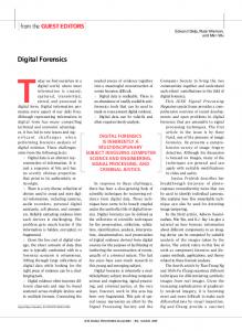
Figure 1: (a) Proposed architecture of a SNVMM. (b) SPECU architecture and NVMM modifications for sneak path encryption. the attacker to steal the data after power down.
3.
THREAT MODEL
We focus on the attacks that are specific to NVMM. The following attack scenarios are considered in this paper: Attack 1 : The attacker has physical access to the NVMM either during system operation or after power down, and can steal the NVMM to leak sensitive data using a brute force attack or a known-plaintext attack. Attack 2 : The attacker has physical access to the NVMM and the system. He can read and write data to the NVMM and determine any secret keys used for securing the NVMM using a chosen-plaintext or an insertion attack. Attack 3 : The attacker has physical access to the NVMM during power down operation and attempts a cold boot attack [10]. During power down, there is a delay between the initiation of power down and the time when all data on the NVMM is secured. The attacker exploits this delay and leaks data from the NVMM before it is completely secure. Other Attacks (not targeted): NVMMs have limited write endurance. ‘Denial of service’ is a type of attack that corrupts data, or forces the system into an unstable state and crashes. Attacks where specific data patterns are written to the NVMM to accelerate aging and damage the memory have been presented in [6]. NVMMs are susceptible to physical attacks. Data may also be corrupted by environmental effects such as heat and gamma rays. Physical attacks can only be prevented by increased physical security, and environmental effects can be mitigated by errorcorrection codes and/or physical shielding [8].
4. SNVMM ARCHITECTURE Fig. ?? shows the SNVMM architecture using a typical two level memory architecture. The processor and cache operate on the unencrypted (plaintext) data. The Sneak Path Encryption Control Unit (SPECU) is between the NVMM and the L2 cache providing ISA-independent memory encryption. The SPECU protects the NVMM by using SPE to convert the plaintext to ciphertext. Encrypted data (ciphertext) is stored in the NVMM. To perform encryption/decryption using SPE, we use sneak paths in the NVMM (described in Section 5). Sneak paths are detrimental to the read/write operation of the NVMM. Hence, the NVMM is modified to introduce sneak paths on demand.
4.1
SPECU
A SPECU, shown in Fig. ??, utilizes SPE to secure the NVMM and works as follows: Initialization: We assume that the computer uses a Trusted Platform Module (TPM) that ensures integrity of the platform [11]. During power-on, the TPM authenticates the NVMM and sends the key to the SPECU. The SPECU stores the key in a volatile memory (either SRAM or DRAM). Hence, the key is lost on power down. Read Operation: Data is read from main memory only on a ‘cache miss’. When data is requested from the NVMM, the read operation is performed in two phases. In the decryption phase sneak paths are introduced in the crossbar. The PRNG generates a pseudorandom sequence (using the 88-bit key as a seed) that is mapped to voltage pulses and address locations (determined in Section 5.5) using Look-up Tables (LUT). Each voltage pulse is applied to the corresponding address locations in order to decrypt the ciphertext stored in the crossbar (details in 5). During the read phase sneak paths are eliminated and the data is read out. Write Operation: The write operation occurs in two phases. During the write phase the plaintext is written to the NVMM, then during the encryption phase (all transistors are turned ON enabling sneak paths) SPE applies a voltage pulse at the address locations generated by the PRNG. This encrypts the plaintext.
5.
SNEAK PATH ENCRYPTION
We use a metal-oxide memristor based NVMM to illustrate SPE. SPE can be adapted for use with any Resistive RAM or PCM based NVMM. Fig. 2a shows the encryption/decryption operation for a 4×4 crossbar using a 10-bit key (size of the key varies with size of the crossbar as shown in Section 5.4) which is the seed of the PRNG. The key structure is explained in Section 5.4. The PRNG generates a sequence of four 10-bit numbers. The first 5-bits are mapped to a a pulse width and voltage and the last 5-bits are mapped to an address in the NVMM using the LUT. At each address location, the corresponding voltage is applied, encrypting all surrounding memory cells as sneak paths are enabled (The process is described in 5.2). The addressed cell is called point of encryption (PoE). The group of cells whose resistance change due to applying a pulse at the PoE is called a polyomino.1 To encrypt the NVMM we use the four voltage pulse-PoE pairs generated by the PRNG and LUT. The set of PoEs (obtained by solving the integer linear problem in Section 5.5) ensures that all memory cells are encrypted. To study the effect of parametric variations on the encryption operation we use a Monte-Carlo analysis. We vary the wire resistance by ±5% and see that there is no change in the shape of the polyomino. Macro level changes to the device/crossbar parameters change the shape of the polyomino showing significant effect on the encryption operation.
5.1
NVMM
The metal-oxide NVMM used is constructed as a crossbar [12]. The memristors support four level cells (MLC-2) that stores two bits in a single cell. As shown in Fig. 3a, a metal-oxide memristor is in series with a transistor at the intersection of each pair of perpendicular wires (1T1M crossbar). In a 1T1M crossbar the gates of all transistors in the same row are connected. When a memristor is addressed, all transistors on the addressed row are turned ON, allowing current to flow only through memristors in that row eliminating sneak paths. Only one cell in a crossbar may be accessed at a time. Hence, an NVMM consists of multiple crossbars that are accessed simultaneously to read a whole 1 A polyomino is any plane geometric figure formed by joining one or more equal squares edge to edge.
Key
Sequence from PRNG Sequence 2 Sequence 3
Sequence 1
01011 11100
01011 11100
1
2
3
4
9
10
11
12
17
18
19
20
25
26
27
28
33
34
35
36
Sequence 4
5
6
7
8
13
14
15
16
21
22
23
24
29
30
31
32
37
38
39
40
45
46
47
48
53
54
55
56
61
62
63
64
0.85V
01011 11110 01010 10111 01010 00100
0.76V
Pulse width LUT
0.1μs 0.07μs 0.04μs 0.1μs +1V
-1V
+1V
(4,1)
(2,2)
(3,3)
(1,4)
-1V
Address LUT
0.97V
0.97V
Encrypt Step 1
Encrypt Step 2
Encrypt Step 3
Encrypt Step 4
1V
PoE 2
PoE 3
PoE 4
Ciphertext
00 11 10 00
01 11 10 00
01 11 10 00
01 11 11 00
01 01 01 00
01 01 01 00
41
42
43
44
11 01 01 10 00 00 11 10
11 01 01 10 01 10 11 10
11 00 10 01
11 00 10 00
11 00 10 00 10 01 11 01
49
50
51
52
11 01 01 10
10 01 11 11 11 00 01 10
10 01 11 01
01 10 10 10
11 00 00 01 01 00 11 10 11 00 01 10
11 00 01 00
11 00 01 00
57
58
59
60
Decrypt Step 4
Decrypt Step 3
Decrypt Step 2
Plaintext
PoE 1
PoE 3
(a)
0.84V
0.99V
0.97V
0.96V
Decrypt Step 1
PoE 1
Incorrect plaintext
PoE 2
01 11 10 10
01 11 10 10
01 10 10 10
01 10 10 00 10
PoE 4
11 11 10 11 01 10 01 10
11 00 11 10 11 01 10 01 10
10 00 10 01
01 00 00 00
01 00 00 00
10 00 01 01 01 00 11 01 10 01 00 00 00
Decrypt Step 4
Decrypt Step 3
Decrypt Step 2
01 01 11 11 01 00 00 00
0.77V
Ciphertext
00 01 01 00 01 01 01 00 10 00 10 00 11 00 10 00 01 01 11 01 10 01 11 01 01 00 00 00 11 00 01 00
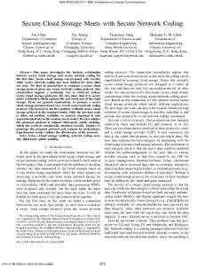
Figure 4: One possible Polyomino (grey) and voltage across memory cells for a 1V pulse applied at PoE (red). Memory cells with a voltage < Vt (white) are not affected.
Decrypt Step 1
(b) Figure 2: (a) Encryption/Decryption in a 4×4 crossbar. (Red: PoE, Grey: polyomino, Green: encrypted cells). (b) Attempted decryption using improper sequence of PoEs. Iprimary
Vdd
Vdd
M11
Vdd M12
Vdd M21
M22
-Vdd
-Vdd (a)
Ioutput Transistor Control
Iprimary
Vdd
Vdd
M11
Isneak
M21
-Vdd
Vdd M12
Vdd M22
-Vdd (b)
Ioutput Transistor Control
Figure 3: (a) A 2×2 1T1M crossbar. Iprimary flows through the addressed memory cell (M12 ).. Only transistors on addressed row are turned on. (b) Sneak paths in a 2×2 1T1M crossbar. Sneak paths are introduced by turning on all transistors. A sneak path current (Isneak ) flows through M11 , M21 and M22 corrupting the output current (Ioutput ) word. The encryption relies on sneak paths. As shown in Fig. 3b, we modify the peripheral circuitry of the crossbar circuit to control sneak paths. The peripheral circuitry ensures that sneak paths are introduced in a 8×8 region of the crossbar allowing proper encryption/decryption.
5.2
Encryption
Applying a voltage pulse to any addressed memory cell, in the presence of sneak paths, results in a voltage difference across adjacent cells. Resistance are either increased or decreased. As shown in Fig. 4, applying 1V to the PoE shown in red, results in voltage difference across cells in the polyomino. Cells with a voltage less than the transistor threshold voltage (Vt ) are not affected. The cells affected are unique to each PoE based on the physical parameters of the crossbar and the data stored in each cell. Applying a voltage at the PoE changes the resistance of the cells in the polyomino. Different PoEs with overlapping polyominos encrypts the entire memory. The key includes the voltages applied at each PoE and the sequence in which they are applied. Although SPE applies multiple pulses across each memristor, it has negligible effect on the endurance of the memory cells since the resistance change is small compared to the typical write operation [13].
5.3
Decryption
To decrypt the ciphertext the sequence of PoEs in encryption is used in reverse. Memristors display hysteresis and a different voltage pulse width is required during encryption and decryption. For example, Fig. 5 shows the encryption and decryption process of a single memristor. The memristor first stores a logic 10 (plaintext). An encryption pulse of 1V with a width of 0.071µs is used to encrypt the memris-
Figure 5: Decryption in a single memristor cell. Decryption pulse is of a different pulse width compared to the encryption pulse due to non-linear memristor characteristics. tor, increasing its resistance to 172kΩ (logic 00). Due to the hysteretic nature of the memristor, the pulse width required to decrypt the memristor is of a different width. As we can see in Fig. 5 a -1V pulse of 0.015µs is required to properly decrypt the ciphertext. Fig. 2a shows the decryption operation of a 4×4 crossbar. The sequence in which the polyominos are decrypted is extremely important for proper decryption. In Fig. 2b, we decrypt the ciphertext using the same PoEs, but in an order different from encryption. Although the PoE locations used are the same as encryption, the shape of the polyomino will be different and depend on the data stored in the crossbar. Every time a voltage is applied at a PoE, the resistance of every memory cell within the polyomino changes. This in turn changes the shape of polyomino of the next PoE.
5.4
Secret Key
The secret key of SPE is used to determine (a) Sequence of PoEs, (b) Voltage applied at each PoE. The sequence of the PoEs and voltages are determined by a PRNG using the key as a seed value. In Section 7 we show that for a 8×8 crossbar we require 16 PoEs to secure 16 the NVMM. Hence, the permutation of any P64 cells can be represented by 44-bits. A typical memristor-based crossbar memory uses several different pulse widths to program the memory cells. We use the same pulse width generator to perform SPE. We assume that the pulse width generator is capable of producing 32 distinct pulse widths of either +1V or -1V. The sequence of 16 voltage/pulse width combinations can be generated by a PRNG with a 44-bit key. Hence, the minimum key size for a 8×8 crossbar is 88-bits. Each element of the generated sequence consists of 44-bits to represent the PoE location and 44-bits to represent the voltage. A secure PRNG with an increased key size [14] may be used to further improve security.
5.5
Determining PoE location
To determine the PoE locations, the following constraints should be met:
Table 1: ILP equations to determine PoE locations in a 8×8 crossbar (can be adapted to any size). Equation M N P Bi,j = 1
∀ 16j6P :
Description Each polyomino has one PoE
i=1
1 6 i 6 MN :
P P
Bi,j ≤ 1
j=1
∀ 1 6 i 6 MN : 1 ≤
P P
Ai,j ≤ 2
j=1 M N P
P P
Ai,j > M N + S
i=1 j=1
Each memory cell used as a PoE not more than once Limits overlapping polyominos to prevent saturation (Section 5.2) Limits minimum number of PoEs.a
Ai,j =Bi+1,j + Bi−1,j +
4 P
Bi−N k,j
k=−4
Objective f unction = min(P ) a b
Represents the polyomino shape shown in Fig. 4.b Minimize number of PoE.
S provides trade-off between security and latency. 0 ≤ S ≤ M N − 1. For boundary cells, equations are customized for PoE location.
1) Cover each memory cell by at least one polyomino. 2) Minimize number of PoEs. Table 1 summarizes the equations used to formulate our problem using Integer Linear Programming (ILP). We use an array B of binary variables to track the PoE location. A PoE address i is assigned to polyomino j if and only if Bi,j =1. The array A of binary variables is used to track the memory locations covered by a polyomino. Hence, Ai,j =1 if and only if polyomino j affects cell i. We formulate our problem as an ILP using arrays A and B as shown in Table 1. The goal of our model is to minimize P, i.e., the number of PoEs used to encode the NVMM. Note that the number of PoEs required for SPE only depends on the cache block size and not the size of the cache.
6.
SECURITY ANALYSIS
We analyze the security strength of SPE against attacks described in Section 3. We model an 8×8 1T1M crossbar using HSPICE. Memristors are modeled using the TEAM model [15] in MATLAB and integrated with HSPICE. We use FICO ILP solver [16] to determine the PoE locations.
6.1
Randomness Tests
To study the randomness of SPE, nine sets of data were collected and analyzed using the NIST randomness test suite [17]. For all tests 150 binary sequences (120 kbits per sequence) were analyzed. 1) Key Avalanche: Avalanche effect is used to examine the sensitivity of SPE to changes in input parameters (i.e., the key or plaintext). In key avalanche effect, the randomness is determined by a three-step process. a) Given an 88-bit random key and a all-zero plaintext the ciphertext is determined. b) With a fixed plaintext, the key is perturbed by flipping the ith bit, where 1 ≤ i ≤ 88. c) The ciphertext from STEP 1 and the ciphertext from STEP 2 are XORed to generate the data set. 2) Plaintext Avalanche: Similarly, in the case of the plaintext avalanche, we use a random plaintext and a 88-bit key of all zeroes. The XOR of the ciphertexts provide the data set. 3) Hardware Avalanche: We introduce another type of avalanche effect that is unique to SPE. In hardware avalanche we use an all-zero plaintext and an all-zero key. We perturb the physical parameters (wire resistance, resistance range of memristor, etc) of the crossbar past the parametric variations and study the effect on the ciphertext. The physical parameters are perturbed from 5-10% in steps of 0.5%. 4) Plaintext/Ciphertext Correlation: To study the correlation of plaintext/ciphertext pairs, n plaintexts (PT) are encrypted using SPE. Given a random 88-bit key and n random PT blocks, a binary sequence is constructed concate-
Table 2: Number of failed sequences (out of 150) for each NIST randomness test [17] applied to each data set. Data Set → Avalanche PT/CT Rnd. Low Den. High Den. Test ↓ Key PT h/w corr. PT/CT Key PT Key PT F-mono 0 0 2 0 1 2 0 2 1 F-block 0 0 2 1 0 1 0 2 1 Runs 2 3 0 0 0 1 0 0 0 LroO 2 3 0 0 0 2 0 0 0 BMR 0 1 0 0 0 2 0 1 2 DFT 0 0 1 0 0 0 0 2 0 NOTM 0 0 0 0 1 0 3 0 1 OTM 0 0 0 2 0 0 2 0 0 Maurer 4 2 0 0 0 0 3 2 2 Lin. Com. 0 0 0 0 0 0 1 1 1 Ser. Com. 0 1 0 0 0 0 0 0 0 App. Ent 0 2 5 0 2 0 0 0 1 Cusums 0 0 0 0 1 0 0 2 1 Rnd. Ex. 2 2 3 0 0 3 2 1 3 REV 2 2 3 0 1 3 1 4 5
nating the results of applying the XOR operator on the PT and its corresponding ciphertext (CT). 5) Random Plaintext/Key: To examine the randomness of ciphertext (based on random plaintext and random 88-bit keys), a data set is constructed as a result of the concatenation of n ciphertext blocks using n random plaintexts and a random 88-bit key. 6) Low Density Plaintext: Two data sets are created based on low-density blocks used as plaintext. Each data set consists of n ciphertext blocks. These ciphertext blocks are formed from one all-zero plaintext block, n plaintext blocks of a single one and 127 zeroes, and 8001 plaintext blocks of two ones and 126 zeroes. 7) Low Density Key: Two data sets are created based on low-density blocks used as an 88-bit key. Each data set consists of n ciphertext blocks. These ciphertext blocks are formed from one all-zero key, 88 keys of a single one and 87 zeroes, and 3828 keys of two ones and 86 zeroes. 8) High Density Plaintext: Two data sets are created based on high-density blocks used as plaintext. Each data set consists of n ciphertext blocks computed using SPE. These ciphertext blocks are formed from one all-one plaintext block, 128 plaintext blocks of a, and 8,128 plaintext blocks of two zeroes and 126 ones. 9) High Density Key: Two data sets are created based on high-density blocks used as plaintext. Each data set consists of n ciphertext blocks computed using SPE. These ciphertext blocks are formed from an all-one key, 8 key blocks of a single zero and 7 ones, and 28 key blocks of two zeroes and 6 ones. Table 2 shows the number of sequences that fails each NIST test described in [17]. With a significance level of 0.01, not more than 5 sequences are allowed to fail a test. SPE passes all NIST tests. However, it needs to be noted that the randomness of SPE is highly dependent on the number of PoEs. Initial tests using SPE with fewer than 16 PoEs (for a 8×8 crossbar) fail a large number of tests. Randomness increases with an increasing number of overlapping polyominos. Hence, with more than 16 PoEs SPE is sufficiently random.
6.2
Defending against Attack 1
The attacker steals the NVMM either during system operation or after power down. The key which is stored in a volatile memory, is lost. Data may only be leaked using a brute force attack.
6.2.1
Ciphertext-only/Brute Force Attack
SPE encrypts 64 bytes of data (cache block size) at a time. Four 8×8 crossbars are used to store 64-bytes of data. Using our ILP model, an 8×8 crossbar requires 16 PoEs to encrypt the entire memory. In SPE, the sequence in which voltages are applied to PoEs is critical for decrypting the 64 data. Using a brute force attack we have P16 possible PoE sequences. We assume 32 discrete pulses (16 pulse widths
Number of cells in a 8x8 crossbar
Overlapped
Non-Overlapped
64
6.4
56
40
6.4.1
32
24 16 8
0 10
11
12
13 14 Number of PoE
15
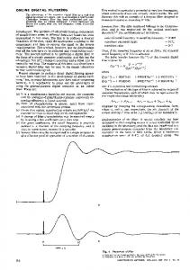
16
17
Figure 6: Polyomino coverage in an 8×8 crossbar for various numbers of PoEs. Cells covered by a single polyomino create security vulnerabilities. for both ±1V) that can be applied at each PoE, resulting in 3216 voltage combinations. Hence, a brute force attack takes ∼1032 years (100ns per PoE) to determine the key. A similar attack on an AES block cipher takes ∼1038 years. What if attacker knows the ILP? Even if the attacker has access to the ILP, a brute force attack is required since the PoE sequence is unknown. The attacker has to check 16! ×1616 combinations which takes ∼ 1019 years. Data decryption can only be performed on the same SNVMM it was encrypted. This prevents parallelization of the brute force attack by creating several copies of the data. Also a brute force attack may force the NVMM to reach its endurance limit [13], destroying the memristors and any data stored on it.
6.2.2
Known-plaintext Attack
The attacker knows part of the plaintext and the corresponding ciphertext, because of known structures like file headers that are encrypted together with the unknown parts of the plaintext. Although the attacker has access to a plaintext-ciphertext pair and the PoE addresses, the shape of the polyomino and the pulse widths of the voltage applied at each PoE is unknown to the attacker. Based on the initial and final resistances of the memristors at the PoEs, the attacker can determine the applied voltage pulses. However, if the memory cell is encrypted by more than one overlapping polyomino, several possible pulse combinations (one at each PoE) can be applied to reach the final resistance. Fig. 6 shows the correlation between the number of PoEs and the coverage of cells by polyominos. In this figure the red/green bars show the cells covered by one/multiple polyominos. Cells covered by a single polyomino are vulnerable. Cells covered by more than one polyomino are secure, since multiple pulse combinations can result in the same resistance. Assuming that the pulse generator used in the NVMM is capable of generating 32 different pulse widths, and each voltage pulse is applied across 16 different PoEs, which may be ordered in 16! possible sequences, the attacker will have to resort to a brute force attack.
6.3 6.3.1
Defending against Attack 2 Chosen-plaintext Attack
The attacker performs a chosen-plaintext attack where the attacker stores any plaintext in the NVMM and has access to the corresponding ciphertext. The attacker faces a challenge similar to a known-plaintext attack. The overlapping polyominos prevent the attacker from determining the voltage pulses applied. Even for an all-zero plaintext the ciphertext is sufficiently random (as seen in Section 6.1).
6.3.2
Defending against Attack 3
48
Insertion attack
In an insertion attack, the attacker knows a ciphertextplaintext pair and has the capability to make the SPECU encrypt the same plaintext with the same key again, but with one inserted bit inverted that is known to the attacker. The attacker performs a statistical analysis to determine the key. In Section 6.1, we apply NIST randomness tests [17] to data collected using plaintext avalanche and show that no correlation can be determined for use in an Insertion Attack.
Cold Boot Attack
During power down, there is a delay between the initiation of power down and the time when all data on the NVMM is secured [10]. The attacker may exploit this delay and leak data from the NVMM before it is completely secure. DRAM memory retains its data for up to 3.2 seconds after power down [10]. For an 8×8 crossbar our encryption technique uses 16 write operations (one at each PoE) in order to encrypt one block of data. Each write operation takes around 100ns and hence it takes 1600ns to encrypt 64 bytes of data. On a power down, all data residing in the cache is written back into the NVMM and encrypted. It is extremely unlikely that the entire cache is written back to the memory, but even in such case it takes 32.7ms (compared to 3.2 seconds in DRAM) to encrypt all the data stored on the 2Mb cache.
7. EXPERIMENTAL EVALUATION We evaluate the performance impact of SPE using Zesto [18], a detailed cycle accurate full-system simulator. We model a 3.2 GHz, single-threaded, 4-issue out-of-order processor core. The private L1 instruction and data caches are 8-way set associative, 32KB in size, and incur an access latency of 4 cycles. The shared L2 cache is 16-way set associative, 2MB in size, and has 16 cycle access latency. All caches have 64-bit line size and use LRU replacement policy. We model the main memory as a single-rank, 800 MHz, 2GB with 8 devices (128MB per device). We simulate two versions of SPE. In ‘serial sneak path encryption’ (SPE-serial ), the decrypted data block remains decrypted on the NVMM until there is a write back or for a fixed period of time. In this case some data on the NVMM is unencrypted and may be leaked by an attacker. ‘Parallel sneak path encryption’ (SPE-parallel ) encrypts data immediately after a read operation. Each read operation from NVMM is delayed by 16 cycles for the decryption process. In SPE-parallel when the data is decrypted, it is sent to the cache and then re-encrypted immediately. In this implementation, each read operation from main memory to cache is delayed by 16 cycles for the decryption process and another 16 cycles for encryption. We also evaluate the performance of AES block ciphers (without ‘least used’ encryption [4]). We compare these results to both stream ciphers [8] and i-NVMM [4]. We use a number of SPEC CPU2006 benchmarks circuits [19]. All benchmarks are executed for 500 million instructions. Performance Overhead : Fig. 7 shows the performance overhead of SPE compared to AES and i-NVMM [4]. The performance impact of SPE-serial is around 1.5% compared to 0.5% of i-NVMM. However, both i-NVMM and SPEserial use partial encryption (some parts of the memory are unencrypted at any given point of time). Partial Encryption: Fig. 8 shows the percentage of the encrypted memory at any given time. AES always ensures that 100% encryption but has a performance impact of 14%. i-NVMM leaves 73% of the NVMM unencrypted. In SPE-serial on average 99.4% of the data in the memory is encrypted at all times. SPE-parallel encrypts 100% of the NVMM at a 3% performance impact. As shown in Fig. 8, workloads that repeatedly access a single memory page such as bzip2 show significant performance impact in our encryption scheme compared to iNVMM. This occurs due to the fact that i-NVMM only encrypts pages that have not been accessed for a fixed duration. However, in applications that access data from several memory pages, such as sjeng, SPE is more efficient. Table 3 summarizes different encryption schemes. AES has the largest performance impact of 14% arising from its
Table 3: Comparison of SPE with AES block ciphers and stream ciphers Latency (cycles) Avg. Performance Impact % Memory Secure Area Overhead (mm2 )/Technology a b
AES 80 14% 100% 8.0 (180nm)a
i-NVMM [4] 80 1% 73% 5.3 (N/A)b
SPE-serial 32 1.5% 99.4% 1.3 (65nm)
SPE-parallel 16 2.9% 100% 1.3 (65nm)
Stream cipher [5] 1 0.4% 100% 6.18 (65nm)
Can be approximated to ∼ 2.2mm2 in 65nm Technology not mentioned in paper [4] AES
Performance Overhead
12.00%
i-NVMM
SPE-serial
SPE-parallel
79% 22% 36%
14%
10.00% 8.00% 6.00% 4.00% 2.00% 0.00%
Figure 7: Comparison of SPE to other encryption techniques [4, 8]
% data kept in encrypted form
AES
i-NVMM
SPE-serial
SPE-parallel
100.00% 80.00% 60.00% 40.00%
20.00% 0.00%
Figure 8: Percentage of memory that is kept encrypted. large latency. i-NVMM reduces performance impact to 1% by using a ‘least used’ encryption scheme. In i-NVMM on average 73% of the data is encrypted during run time making it vulnerable to Attacks 1 and 3. SPE-serial and SPEparallel have an area overhead of 1.3mm2 . Stream ciphers provide a low latency and high security (100%) encryption but suffers from an area overhead ∼5× of SPE.
8.
CONCLUSION
Although NVMM has recently attracted attention, various security concerns continue to arise over such devices. Sensitive data written to NVMM persists even when the system is powered down and can be leaked easily. We have presented sneak path encryption that exploits the physical parameters of the NVMM to secure data. Data secured by SPE can only be decrypted on the same SNVMM used for encryption. SPE also has a low performance and area overhead. The advent of non-volatile caches calls for faster encryption methods. Thus, extending SPE to consider high speed non-volatile cache memories is an interesting direction.
9.
REFERENCES
[1] J. Hutchby and M. Garner, “Assessment of the potential and maturity of selected emerging research memory technologies,” International Technology Roadmap for Semiconductors, July 2010, http://www.itrs.net. [2] D. B. Strukov et al., “The missing memristor found,” Nature, vol. 453, no. 7191, pp. 80–83, 2008. [3] Micron, “About phase change memory,” http://www.micron.com/products/phase-changememory.
[4] S. Chhabra and Y. Solihin, “i-nvmm: a secure non-volatile main memory system with incremental encryption,” in Int’l Symp. of Circuits and Sys., 2011, pp. 177–188. [5] J. Yang et al, “Improving memory encryption performance in secure processors,” IEEE Trans. on Computers, vol. 54, no. 5, pp. 630–640, May 2005. [6] M. K. Qureshi et al., “Enhancing lifetime and security of pcm-based main memory with start-gap wear leveling,” in IEEE/ACM Int’l Symp. on Microarchitecture, 2009, pp. 14–23. [7] T. Gilmont, J. Legat, and J. J. Quisquater, “Enhancing the security in the memory management unit,” Proceedings of EUROMICRO Conference, vol. 1, pp. 449–446, 1999. [8] J. Valamehr et al., “Inspection resistant memory: architectural support for security from physical examination,” SIGARCH Computer Architecture News, vol. 40, no. 3, pp. 130–141, June 2012. [9] E. Zenner and M. Boesgaard, “How secure is secure? on message and iv lengths for synchronous stream ciphers,” Cryptico A/S Tech Report, 2005. [10] R. Venkatesan et al., “Retention-aware placement in dram (rapid): Software methods for quasi-non-volatile dram,” in Int’l Symp. on High Performance Computer Architecture, no. 157–167, 2006. [11] Z. Huanguo et al., “Design and implementation of the tpm chip j3210,” in Trusted Infrastructure Technologies Conf., 2008, pp. 72–78. [12] M. Ziegler and M. Stan, “Design and analysis of crossbar circuits for molecular nanoelectronics,” in IEEE Conf. on Nanotechnology, 2002, pp. 323–327. [13] J. J. Yang et. al, “High switching endurance in taox memristive devices,” Applied Physics Letters, vol. 97, no. 23, pp. 232 102–3, 2010. [14] R. S. Katti and R. G. Kavasseri, “Secure pseudo-random bit sequence generation using coupled linear congruential generators,” in Int’l Symp. on Circuits and Sys., 2008. [15] S. Kvatinsky et al., “Team–threshold adaptive memristor model,” IEEE Trans. on Circuits and Sys., April 2012. [16] “Fico xpress optimization suite. [online].” “http:// www.fico.com/ en/ Products/ DMTools/ Pages/ FICO-Xpress-Optimization-Suite.aspx ”. [17] A. Rukhin et al, “A statistical test suite for random and pseudorandom number generators for cryptographic applications,” NIST. [18] G. H. Loh et al., “Zesto: A cycle-level simulator for highly detailed microarchitecture exploration,” in IEEE Int’l Conf. on the Performance Analysis of Software and Systems, A 2009. [19] S. P. E. Corporation, “SPEC2006 benchmark v1.2,” http:// www.spec.org/ cpu2006/ , 2011.