SECURE OPTICAL COMMUNICATIONS UTILIZING PSK MODULATION, POLARIZATION MULTIPLEXING AND COHERENT DIGITAL HOMODYNE DETECTION WITH WAVELENGTH AND POLARIZATION AGILITY Aviv Salamon, Guy Levy-Yurista, Michael Tseytlin, Pak S. Cho, and Isaac Shpantzer, CeLight Inc., 12200 Tech Road, Suite 300, Silver Spring, MD 20904
[email protected] ABSTRACT Data Encryption and User Authentication are the major communications security (ComSec) approaches used in today’s communications networks. While these methods provide an efficient means to secure the sensitive information, they do not prevent a hostile opponent from jamming the signal or tapping the link. We present here an analysis of a coherent optical communications system providing secure communications in free-space or over fiber. After reviewing the basic principles of Coherent Optical Communications we present a system using polarization/frequency agility to secure the data link at the optical layer. The key building blocks will be presented, including a QPSK transmitter, and an optical hybrid combined with a coherent digital receiver. A description of CeLight’s LiNbO3 integrated implementation of the transmitter and the receiver will be detailed. Next, a theoretical analysis demonstrating the capabilities of such a secure communications system to send data over fiber and in free space eliminating the need for optical filtering and lambda-based de-multiplexing. Finally, we present an experiment demonstrating the ability of the proposed frequency hopping solution to avoid an eavesdropper from intercepting the data channel.
tapping capabilities, enabling the interception and collection of data. Increasing computation power and efficient algorithms may enable the eventual deciphering of this maliciously collected data. We present here a method and system based on CeLight’s VectorWAVE™ platform to provide a more fundamental level of security to the communications link at the optical layer, whether free-space or fiber, making the malicious collection of data considerably harder. The proposed method includes using phase shift keying (PSK) modulation and coherent digital homodyne detection. This modulation and detection scheme provides inherent frequency selectivity and enables the incorporation of wavelength agility into the communications link without reliance on narrowband tunable optical filters. In addition, the preservation of the signal phase information in the receiver enables the implementation of a digital polarization diversity receiver without reliance on optical components, thus making polarization multiplexing and polarization agility implementable. As a result, a potential eavesdropper will have to use more complex receivers, covering a much wider bandwidth of optical spectrum and develop a novel class of devices accounting for the rapid signal polarization changes of the multiplexed signals. SECURE OPTICAL LAYER COMMUNICATIONS SYSTEM
INTRODUCTION Techniques used today to secure communications networks consist of Data Encryption and User Authentication. Data encryption makes the deciphering of information that has been accessed without authorization more difficult, while user authentication procedures are used to prevent unauthorized users from gaining access to the data in the first place. While these methods provide ways to secure sensitive information, they do not prevent physically tapping into the link and collecting the transmitted data. Commercially available off the shelf equipment provides such optical link
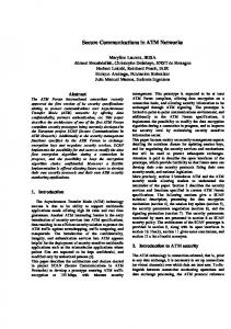
Figure 1 shows a single transmitter, one of many to be used in such a secure optical Communications system. A low linewidth tunable laser is optionally intensity modulated using a Mach-Zehnder Interferometer (MZI) and shaped into a train of RZ (return to zero) pulses. The carrier is split into two paths; each intended to carry data on a different polarization state (H and V). The data is encoded in the phase of each of the optical carrier polarization component using a phase modulator or a quadrature modulator, e.g. CeLight’s LiNbO3 quadrature modulator shown in Figure 2. The two signals are then added on two orthogonal polarization states using a polarization beam combiner (PBC) and transmitted. A
1 of 9
polarization scrambler may be used to change the polarization state of the signal. H Data
H Tuanble Laser
Pulse Shaping MZI
PSK Modulator
Splitter
PBC
to link
PSK Modulator V Data
V
Polarization Scrambler
Figure 1. PSK dual-polarization transmitter schematic. A low linewidth tunable laser is shaped into a pulse train using a MZI, then split into two paths each modulated with an independent data stream using a PSK modulator, and combined again on orthogonal polarization using a polarization beam combiner (PBC). A polarization scrambler is used to rapidly change the polarization of the transmitted signal enhancing its immunity to tapping.
The local oscillator (laser) L, which is also tunable, is supposed to be phase-locked to the incoming signal S. The actual implementation of the phase-lock loop (PLL) is done in the digital part of the receiver, eliminating the need for a complex optical PLL. The optical hybrid and balanced diodes act as a mixer, down-converting the signal from the optical band to the electrical baseband. It is important to note that since the transformation is linear, all of the filtering (for noise reduction and separation of carriers) can be performed in the electrical domain, with no reliance on narrow optical filters. For the same reason the signal received by the DSP on arbitrary polarizations [SH’ SV’]T can be rotated (by multiplying it with the appropriate recovery matrix, M) to recover the original polarization state of the signal M·[SH’ SV’]T=[SH SV]T, and the data on each polarization can then be demodulated. H' 90 Optical Hybrid
I Data
Optical in
Phase control
PBS
Optical out
Q Data
Figure 2. CeLight’s LiNbO3 QPSK modulator schematic. The carrier signal is divided into two arms, carrying the inphase (I) and quadrature-phase (Q) parts of the modulation. A MZI on each arm modulates the carrier’s amplitude according to the data, and a 90° phase shift is induced between the two arms using a phase modulator (PM). Finally, the two arms are combined using a coupler.
In the receiver, schematically shown in Figure 3, the signal is split into two (arbitrary) orthogonal polarizations (H’ and V’) and each is mixed with a local oscillator in an optical 90° hybrid. The hybrid, shown in Figure 4, takes the signal S and the local oscillator L and produces four outputs: (i) S+L, (ii) S-L, (iii) S+jL and (iv) S-jL. Each of the optical output pairs (i), (ii) and (iii), (iv) is collected by a pair of balanced diodes whose photocurrents are subtracted, as shown in Figure 5, to produce currents proportional to |S+L|2-|S-L|2=4·Re{SL*} and |S+jL|2-|SjL|2=4·Im{SL*}, together constructing the complex value SL*. Following this (linear) transformation the signals are electrically filtered, sampled and then processed.
DC
V'
90 Optical Hybrid
Balanced Receiver H' I Balanced Receiver H' Q Tuanble Laser
DSP
H, V Data out
Balanced Receiver V' I Balanced Receiver V' Q
Figure 3. PSK dual-polarization digital homodyne receiver schematic. The incoming signal is arbitrarily split into two orthogonal polarizations using a polarization beam splitter (PBS), each polarization is input into a 90° optical hybrid, which mixes the signal S with a local oscillator L, shared by the two hybrids using a directional coupler (DC). Each hybrid output pair {(S+L), (S-L)} and {(S+jL), (S-jL)} is input into a balanced receiver that yields a signal proportional to Re{SL*} and Im{SL*} respectively. The digitized samples are processed to recover the original polarization state of the signal to compensate for the phase and frequency offsets of the lasers, and to demodulate the data.
The system presented above consists of many such transmitters and receivers sharing the same bandwidth, all changing wavelengths and polarization states synchronously or asynchronously (where the number of wavelength slots is much bigger than the number of carriers). Notice, that while it can be relatively easy to follow a carrier when there are no other carriers present, the presence of a significant number of carriers changing wavelengths synchronously or asynchronously makes the task harder.
2 of 9
transmitter (serving as the signal carrier) and receiver (serving as the local oscillator). Some additional time (in the order of microseconds) will be needed to relock the receiver onto the incoming data stream. A major advantage of using such coherent detection scheme is that there is no need for narrow tunable optical components, whose tuning and settling times are on the order of several milliseconds, because the local oscillator transfers the optical signal linearly to the electrical domain.
90° Hybrid S
PM
DC
S+L
S-L
L
PM
DC
S+jL
S-jL
(a)
POLARIZATION AGILITY
(b) Figure 4. 90° optical hybrid. The hybrid takes two input signals S and L, and mixes them with four relative phase relations, adjusted by the phase modulators (PMs): (i) S+L, (ii) S-L, (iii) S+jL, and (iv) S-jL. DC = Directional Coupler. (a) a schematic representation (b) CeLight’s actual device.
Another major advantage of the secure optical system discussed above is that no optical components are required in order to recover the polarization state of the signal in the receiver. The linear transformation of the signal from the optical to the electrical domain and its digitization enables the performance of digital polarization compensation, thus avoiding the problematic use of slow, non-endless optical polarization compensators, and the incurring losses [1]. Furthermore, an enhancement in the security level can be achieved by applying rapid changes to the polarization state of the signal using a scrambler in the transmitter, followed by the appropriate counter adjustment of the digital polarization compensation matrix in the receiver. Moreover, allowing the transmission of two different data streams on the same carrier frequency, using the two orthogonal polarization states, considerably increases the security level of the transmitted data, while doubling the channel capacity and spectral efficiency. PERFORMANCE VS. CHANNEL NOISE
S+L Re{SL*} S-L Balanced Diodes
TIA
Filter
ADC
Figure 5. A balanced receiver schematic. A pair of balanced diodes detects the two light signals; their output is subtracted and amplified by a trans-impedance amplifier (TIA), filtered and sampled in an analog to digital converter (ADC).
ADVANTAGES OF THE SECURE OPTICAL COMMUNICATIONS SYSTEM WAVELENGTH AGILITY The main characteristic enabling the secure optical system discussed above is its wavelength agility. Each carrier can change its wavelength by tuning the lasers in the
The secure optical system discussed above utilizes coherent phase shift keying (PSK) demodulation, in particular the preferred modulation scheme will be QPSK (quadrature PSK), where each symbol is encoded with two (2) bits per polarization, as shown schematically in Figure 6, [2]. It should be noted that CeLight’s quadrature modulator 3], designed for QPSK modulation, is able to perform any modulation scheme (mPSK, QAM, etc.) given the appropriate driving electronics. Figure 7 shows calculated BER vs. SNR per bit curves for QPSK/BPSK, DQPSK, DBPSK [3] and intensity modulation direct detection (IMDD) [5]. The noise is considered to be additive white gaussian noise (AWGN) and is added before the receiver (optical hybrid). It is clear from these results that using QPSK modulation, the system can tolerate more than twice the noise compared to using IMDD. Note that the QPSK modulation scheme has double the spectral efficiency of BPSK.
3 of 9
closely, relying on electrical filters to perform the separation. Accordingly, a spectral efficiency of 1.6 bits/sec/Hz (40Gbps over 25GHz channel spacing) can be readily demonstrated with these methods and devices.
(a)
PERFORMANCE VS. CHANNEL DISTORTION HI
VI
VQ
HQ
(b) Figure 6. Polarization multiplexed QPSK signal constellation. The signal is divided into two orthogonal polarization states (a). On each polarization two bits are encoded, one on the in-phase (I) and one on the quadrature-phase (Q) of the signal (b).
Since the signal is down-converted linearly to the electrical baseband and digitized, the entire arsenal of digital signal processing methods conventionally used in RF systems becomes available for implementation in the system. Particularly, implementation of channel equalization and compensation for linear channel distortions (e.g. chromatic dispersion, PMD, some atmospheric effects etc.) is attractive. ANALYSIS OF QPSK TRANSMISSION WITHOUT OPTICAL FILTERS Assume that the incoming signal S is composed of N carriers, each with power Ps. The kth carrier’s angular frequency is ωk, and its phase data is ϕk. An AWGN noise namp is added to the signal.
S = Ps ∑ e j(ωk t +ϕk ) + n amp
(1)
k
The local laser oscillator whose power is Pl is tuned to receive the kth carrier
L = Pl e jωk t
(2)
The current in the I channel after the TIA without filtering is:
i = S + L ξ(1 + ε ) − S − L ξ(1 − ε ) + n shot + n thermal 2
Figure 7. Calculated BER vs. SNR per bit for IMDD, DQPSK, DBPSK and QPSK/BPSK modulation schemes.
SPECTRAL EFFICIENCY
2
(3)
Here ξ is the average responsivity of the two balanced diodes, ε2 is the common mode rejection ratio (CMRR), nshot is the total shot noise (induced by the two balanced diodes) and nthermal is the thermal noise induced by the TIA. After low pass filtering we have
Using QPSK and polarization multiplexing enables transmitting four (4) bits of information per symbol (pulse). Accordingly, for the same signal bandwidth the secure optical communications system can deliver four times the information compared to an OOK or BPSK signal transmitted on a single polarization.
(4)
i = 4ξ
In addition, since no optical filters are used to separate carriers in the receiver, we can pack the channels more
4 of 9
(
{ })
k Ps Pl cos ϕ k + Pl ℜ namp +
{ }
2 l +2ξε NPs + Pl + 2 Ps ∑ ℜ namp + namp + l + n' shot + n'thermal
k With n amp being the noise filtered with the receiver local 2 , n’shot and n’thermal are laser oscillator tuned to ωk, and n amp
number of carriers in the optical filter passband for a BER of 2x10⁻³ (9.2dB SNR) and 10-9 (15.6dB SNR).
the filtered |namp|2, nshot and nthermal. Equation (4) consists of the following terms: the desired signal
4ξ Ps Pl cosϕk ,
the
{ }
l-n
beating
noise
k 4ξ Pl ℜ n amp , the s-s beating interference that is
(almost) constant with amplitude 2ξε(NPs+Pl), the s-n beating noise 4ξε Ps
∑ ℜ{n }, l amp
the n-n interference
l
2 2ξεnamp , the shot noise, and the thermal noise.
Assuming that (NSRs-n, NSRn-n)