The learners will complete the following project in Matlab and submit their ...
communication system that uses convolutional encoding with pulse shift keying (
PSK) ... where ωo is the carrier frequency in radians/s and is assumed an integer
multiple of 2π/T. The transmitted signal ... Consequently, the code rate for a (n, 1,
K).
PROJECT 6: CONVOLUTIONAL CODES Amir Asif Technical University of British Columbia Surrey, B.C. The learners will complete the following project in Matlab and submit their solutions along with a soft copy of the code in the form of a report. The expected time of completion for the entire project is 2 weeks. Report on the first five questions are due by the end of the first week while the complete report is expected to be submitted by the end of the second week. Good luck. Introduction: In this project, we will run a Monte-Carlo simulation to characterize the performance of a binary communication system that uses convolutional encoding with pulse shift keying (PSK) modulation. Figure 1 illustrates the block diagram of such a digital communication system where the input message is denoted by the ✲ Convolutional Encoder
Information Source
Input Sequence m = m1 , m2 , . . . , mi , . . .
Information Sink
✛
Modulator
Codeword Sequence U = G(m) = U1 , U2 , . . . , Ui , . . . with Ui = u1i , u2i , . . . , uji , . . . , uni
Convolutional ✛ Decoder
Detected Sequence � =m m � 1, m � 2, . . . , m � i, . . .
✲
Demodulator ✛
si (t)
❄ AWGN Channel
s�i (t)
Demodulated Codeword Sequence Z = Z1 , Z2 , . . . , Zi , . . . with Zi = z1i , z2i , . . . , zji , . . . , zni
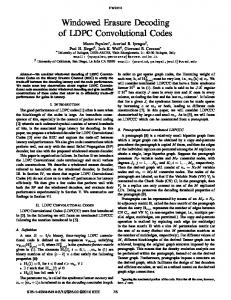
Figure 1: A digital communication system emphasizing channel encoding and modulation. sequence m with each mi representing a binary digit (bit). The index i in mi is the time index, thus m1 is transmitted before m2 and so on with the remaining bits. The channel encoder encodes the input message m U = G(m)
(1)
producing the codeword U that is transmitted through an AWGN channel with power spectral density of No . In this project, a (n, 1, K) binary convolutional encoder is used as the channel encoder. Therefore, a codeword of length n is produced for each input bit. More on convolutional encoder later where we illustrate its operation through an example. The modulation and demodulation scheme used in the digital communication system modeled in figure 1, is the M-ary PSK. Recall that the general representation for the PSK waveforms is � � 2E 2πi � cos ωo t − , i = 1, . . . , M, 0 ≤ t ≤ T (2) si (t) = T M
where ωo is the carrier frequency in radians/s and is assumed an integer multiple of 2π/T . The transmitted signal si (t) has a constant envelope with a duration of T and energy E. In project 5, we implemented the PSK modulator and demodulator using Matlab. These functions are made available to you for this project. In the following section, we focus on the binary convolutional encoder and decoder. Convolutional Encoder: A binary convolutional code is generated by passing the information sequence to be transmitted through a linear finite-state shift register. For a (n, 1, K) convolution code, the shift register consists of K stages and n linear modulo-2 function generators. The input data is shifted into and along the shift register a single bit at a time producing a n-tuples output for each shift. Consequently, the code rate for a (n, 1, K) convolutional encoder is 1/n. To illustrate the working of a convolutional encoder, consider the (3,1,3) convolutional encoder shown in figure 2 where the output U = [Ui1 , Ui2 , Ui3 ] at instant i is obtained from the message bit mi
m
✲ mi
mi−1 mi−2
r r r
❜ Ui1 �✏ ✲ ❜ Ui2 + ✲✒✑ ✲�✏ ✲ + ❜ Ui3 ✲✒✑
Figure 2: A (3,1,3) convolutional encoder. at instant i and the previous (K − 1) (which equals 2 for in our example) message bits mi−1 and mi−2 . The operator ⊕ is the modulo-2 arithmetic operator. Initially, the shift registers are assumed to be in the all zero state. Suppose the first input bit m1 is a 1. At the next clock cycle, the initial content of the registers is moved towards the right by 1 bit and the message bit occupies the left most register. The registers are therefore set to states 1, 0, and 0, i.e., mi = 1, mi−1 = 0, and mi−2 = 0. The value of the three output bits Uij , for i = 1 and 1 ≤ j ≤ 3, are given by Ui1
= mi
(3)
Ui2 Ui3
= mi ⊕ mi−2 = mi ⊕ mi−1 ⊕ mi−2 .
(4) (5)
Solving equations (3-5) for the codeword U1 gives 111. Suppose now that the second bit is a 0. The registers are set to 0, 1, and 0 at the next clock cycle and the codeword U2 is 001. By following this procedure, the codewords Ui can be generated for the remaining message bits. Question 1: Suppose that the registers in figure 2 are initially reset to 0. Find the output codeword sequence U if the input message sequence is given by m = 11011 followed by (K − 1) zeros to flush the registers. Repeat if the registers are initially set to 1 and 1’s are used to flush the registers. In the remaining project, we will assume 0-initial and 0-flush conditions for the registers. There are several alternative methods discussed in the Sklar text that can be used to describe a convolutional code. These include the state diagram, the tree diagram, and the trellis diagram. For implementing in Matlab, we will use an alternate approach of assigning a generator matrix G, just as we did for the block codes. The generator matrix G is defined in terms of n connection vectors, denoted by g1 , g1 , . . ., gn , one for each of the n-modulo-2 adders. Each vector has a dimension K and describes the connection of the encoding shift register to that of the modulo-2 adder. A 1 in the i’th position of the vector indicates that the corresponding stage in the shift register is connected to the modulo-2 adder, and a 0 in a given position indicates that no connection exists. For the (3,1,3) convolutional encoder illustrated in figure 1, the connection vectors are given by � � � � � � g3 = 1 1 1 (6) g1 = 1 0 0 , g2 = 1 0 1 , and
The generator matrix G of the convolutional code is then given by � � T g1 gT2 gT3 G =
(7)
where the subscript T denotes the transpose operation. In order to calculate the output codewords U, the content of the registers at each iteration i is placed in a row vector si which is then multiplied with the generator matrix G, i.e., Ui
= si G.
(8)
In our example of (3,1,3) convolutional code, the content of the register is 1 0 0 for iteration i = 1. The codeword U1 is then given by � � 1 1 1 1 0 0 0 0 1 U1 = 0 1 1 � � 1 1 1 . = The procedure is repeated for the remaining message bits. Question 2: Repeat question 1 using the generator matrix G. Compare the code rate of the algorithm to the theoretical bound (k/n). There are many algorithms that can be used for decoding of convolutional codes. The Viterbi algorithm is probably the most widely used decoding method for convolutional codes. This algorithm is particularly interesting because it is a maximum likelihood decoding algorithm which upon receiving the channel output, searches through the trellis diagram to find the path that is most likely to have generated the received sequence. Details on the Viterbi algorithm are given in section 7.3 of the Sklar text. Question 3: Assume that the transmitted sequence for question 2 with 0 initial state and 0 used to flush the registers, is corrupted with AWGN so that the received sequence is given by 111001100110010011. Using the Viterbi algorithm, find the maximum likelihood information sequence and the number of errors. There are several different implementations of the Viterbi algorithm for detection of binary convolutional code. We will be using the following implementation which consists of six steps. 1. Parse the received sequence into m subsequences of length n. 2. Set the index l to 1 and initialize the state value to (K − 1) bits 0-tuples. The zero state correspond to the initial state. Since at this time, we have not traversed any path in the Trellis diagram, we initialize the corresponding Hamming distance to 0. For decoding of the (3,1,3) convolutional code in our example of fig. 2, the initialization conditions are state = [0 0]; hdistance = [0]; dsequence = [] where we use the notation used in Matlab. The variable state denotes the states being used in the Trellis diagram, the variable hdistance denotes the Hamming distance metric corresponding to that state, while dsequence denotes the decoded sequence. As the algorithm iterates, we assume different values of these variables are saved along different rows. 3. For each of the states included in state, do the following: (a) Assuming 0 as the message bit, append the variables state, hdistance, and output. The Hamming distance is calculated by comparing the n-bit parsed received sequence with the expected code symbols generated as a result of state transitions. (b) Repeat the item (a) assuming 1 as the message bit. For binary code, you will observe that the dimensions of the three variables would be doubled. Note that this step moves you to the (l + 1) stage of the Trellis diagram.
4. If states are repeated in the variable state, delete the entries corresponding to the higher Hamming distance from each of the three variables state, hdistance, and output. This is the path-elimination step of the Viterbi algorithm. 5. If l = m, proceed with the next step; else, increment l by 1 and go to step 3. 6. The decoded sequence is the value of dsequence corresponding to the minimum Hamming distance in hdistance. The minimum value of hdistance gives the number of corrected errors. Based on the information provided above, complete the following questions. Question 4: Write a Matlab function myconvcode that generates (3,1,3) convolution code according to the encoder illustrated in fig. 2. Use 0-initial and 0-flush conditions for the registers. Check your output with the theoretical value that you calculated in question 1. Question 5: Write a Matlab function myviterbi that decodes the codeword sequence U generated by the (3,1,3) convolution encoder shown in fig. 2. Check the function by decoding your answer to question 1. Also, validate the function by solving question 3. In questions 6-10, we will run a Monte Carlo simulation for the binary communication system illustrated in figure 1. As you will note, several of the functions that you wrote in project 5 can be used in the following questions. Question 6: Write a function myinput that simulates the transmission of 5000 bits using the random number generator. To accomplish this task, we use Matlab function rand to generate 5000 random numbers in the range (0,1). This range is divided into two equal intervals, (0, 0.5) and (0.5, 1) where the subintervals correspond to bits 0 and 1 respectively. Save the sequence of transmitted symbols mi ’s as you will be required to compare the sequence with the detected sequence at the receiver. Question 7: The symbols, mi ’s, are encoded using the (3,1,3) convolutional encoder that you designed in question 4. Calculate the output of the convolutional encoder first in terms of bits and then in terms of 4-ary symbols (a1 , a2 , a3 , a4 ) by parsing mi in sub-sequences of 2-bits. Question 8: The symbols, ai ’s, are modulated using a 4-ary PSK defined in equation (2). The signal energy can be normalized to unity, i.e., E = 1 with the carrier frequency ωo = 6π/T and T = 1. Choose a sampling frequency of 1/30s. Plot the waveform for the first 5 symbols. Save the 4-ary sequence ai ’s since we will be comparing the sequence with the demodulated value at the output of the PSK demodulator. Question 9: Add AWGN with a PSD of No = 2 to the waveform generated in question 7. This represents the received waveform. Plot the waveform for the first 5 received symbols and compare with your plots obtained in question 7. Question 10: Using a 4-ary coherent detection scheme, demodulate and detect the sequence of alphabets ai ’s. Compare the detected sequence with the transmitted sequence of question 7 and calculate the symbol-error rate PE . Question 11: Convert the message stream obtained in question 10 to a binary sequence and decode using the Viterbi algorithm implemented in the function myviterbi, your answer to question 5. Calculate probability of the bit error PB . Question 12: Repeat question 5 to 10 for different values of PSD No = 4, 8, 12, and 16 four to five times each and calculate the average values for the probability of errors. Plot the symbol-error rate PE versus the Eb /No ratio for both PSK-modulated sequence without convolutional encoding and PSK-modulated sequence with convolutional coding. Plot and compare with the theoretical limits. For a fair comparison, remember to convert symbol error rate to bit error rate or vice versa. Record your observations and any salient features that you may have observed in the Monte-Carlo simulations.