images is presented using the intelligent scissors. ... Image processing, medical image analysis. ... Intelligent Scissors allow objects within digital images to be.
IJCA Special Issue on “Recent Trends in Image Processing and Pattern Recognition” RTIPPR, 2010.
Segmentation of Abnormal Region from Endoscopic Images using Intelligent Scissors Ravindra S. Hegadi
Shailaja S. Halli
Arpana Kop
Department of Computer Science Karnatak University Dharwad, India
Department of Computer Science Karnatak University Dharwad, India
Department of Computer Science Karnatak University Dharwad, India
ABSTRACT The commonly found abnormalities in endoscopic images are cancer tumors, ulcers, bleeding due to internal injuries, etc. Several methods of segmentation are employed in recent past for proper segmentation of such images. Intelligent scissors is one of the tools for segmentation. Here the segmentation of endoscopic images is presented using the intelligent scissors. This method is used to segment the tumor, abnormal regions and cancerous growth in the human esophagus. Several methods implemented in the recent past have yielded good results. But this method is simpler. Here a seed point is selected then the cost matrix is constructed which gives the costs of the neighbouring points. Using Dijkstra‟s algorithm, the nearest point falling in the same region is selected. The proposed method has shown encouraging results in segmenting the abnormal parts from esophegal endoscopic images.
General Terms Image processing, medical image analysis.
Keywords Intelligent Scissors, Endoscopy, Segmentation, Optimal Path.
1. INTRODUCTION Intelligent Scissors allow objects within digital images to be extracted quickly and accurately using simple gesture motions with a mouse. When the gestured mouse position comes in proximity to an object edge, a live-wire boundary “snaps” to, and wraps around the object of interest. , digital image segmentation tool called “Intelligent Scissors” which allows rapid object extraction from arbitrarily complex backgrounds. Intelligent Scissors formulates boundary finding as an unconstrained graph search [1] in which the boundary is represented as an optimal path within the graph. Live-wire boundary detection formulates boundary detection as an optimal path search in a weighted graph. Optimal graph searching provides mathematically piece-wise optimal boundaries while greatly reducing sensitivity to local noise or other intervening structures. Robustness is further enhanced with on-the-fly training which causes the boundary to adhere to the specific type of edge currently being followed, rather than simply the strongest edge in the neighbourhood. Boundary cooling automatically freezes unchanging segments and automates input of additional seed points. Cooling also allows the user to be much more free with the gesture path, thereby increasing the efficiency and finesse with which boundaries can be extracted. Among the global boundary based techniques, graph searching and dynamic programming are popular techniques used to find the
globally “optimal” boundaries based on some local cost criteria [2, 3, 4, 5 and 6]. They formulate the boundary finding problem as a directed graph or cost functional to which an optimal solution is sought. Montanari [7] was perhaps the first to apply a global optimization algorithm to boundary detection in images. He proposes “a technique for recognizing systems of lines” based on dynamic programming to minimize a heuristic “figure of merit” or cost function and develops a figure of merit for low curvature lines based on image intensity, path curvature and path length. The algorithm detects a line (with local variations) in an artificial image even when the line is hardly visible due to noise. Ballard and Sklansky [8] extend Montanari‟s algorithm by using gradient magnitude, gradient direction and a closure measure in their evaluation function. They use dynamic programming with directed searching to detect circular tumours in chest radiographs. Chien and Fu [9] argue that Ballard and Sklansky‟s decision function is “too specifically designed for one type of application” and develop a more general “criterion” function which has both local (e.g., gradient) and global (e.g., curvature) components. They minimize the criterion function using a modified decision tree search and apply their technique to determine cardiac boundaries in chest x-rays. Martelli [10] shows that any optimization problem using dynamic programming can be formulated as a shortest or minimum cost path graph search. He applies Nilsson‟s [11] A* heuristic graph search algorithm to the boundary detection problem where the heuristic is used to prune the search and thereby reduce computation. His technique successfully identifies multiple touching objects and occluded boundaries in artificial images with Gaussian noise. Udupa [12] formulates optimal two-dimensional boundary finding as a graph search using dynamic programming. Like Martelli [10], he formulates the image grid as a directed graph where pixel corners are nodes and the cracks between pixels are directed arcs. Based on Udupa‟s formulation, and in collaboration with him, Morse et al. [13, 14] present a boundary finding algorithm which computes a piece-wise optimal boundary given multiple input control points. Rather than specify constraints and heuristics for a specific problem, this method utilizes a probabilistic “likelihood” function. Snakes, active contours, and thin plate models are another global boundary based segmentation techniques that have received a great deal of attention [15, 16, 17, 18, 19, 20, and 21]. Active contours are initialized manually with a rough approximation to a boundary of interest and then allowed to iterate over the contour to determine the boundary that minimizes energy functional. Kass, Witkin, and Terzopoulos [19, 20] introduced a global minimum energy contour called “snakes” or active contours. Given an initial approximation to a desired contour, a snake locates the closest 89
IJCA Special Issue on “Recent Trends in Image Processing and Pattern Recognition” RTIPPR, 2010. minimum energy contour by iteratively minimizing an energy functional which Geiger et al. [18] apply dynamic programming to detect deformable contours. They use a noniterative technique that searches for the optimal contour within a large neighbourhood around the initial contour. They utilize a multiscale technique to achieve greater processing efficiency while sacrificing guaranteed optimality. The methods discussed thus far follow a pattern of user input--whether through defining a figure of merit, a decision function, a 2-D template, or an initial active contour, etc. to initialize the algorithm, followed by contour selection based on the input, for the graph searching techniques, or contour refinement of the input, for active contour techniques. If the resulting contour is not satisfactory, this may in turn be followed by one or more iterations of user input (to adjust parameters, change the figure of merit, input a new initial active contour, locally modify an existing contour or energy landscape, etc.) and reapplication of the algorithm. The interactive optimal path selection algorithm, or live-wire technique, was developed as a general image segmentation tool which takes advantage of the multiple optimal paths generated by graph searching techniques. The live-wire technique was developed to overcome the limitations of [13, 14]. Although [13,14] use dynamic programming to compute unrestricted optimal paths from every grid point in the image to every other grid point, it still suffers from the same iterative, non-interactive style as previous graph searching boundary finding methods in that the user inputs a series of control points which are then connected with piece-wise optimal segments into a single contour. There is no immediate feedback to indicate where or how far apart to place the seed points on the boundary. Consequently, multiple iterations, requiring input of multiple control points is typical with this technique.
2. INTELLIGENT SCISSORS The underlying mechanism for Intelligent Scissors is the “livewire” path selection tool. The live-wire tool allows the user to interactively select the desired optimal path from the entire collection of optimal paths (one for each pixel in the image) generated from a specified seed point. The optimal path from each pixel is determined at interactive speeds by computing an optimal spanning tree of the image using an efficient implementation of Dijkstra‟s graph searching algorithm. The basic idea is to formulate the image as a weighted graph where pixels represent nodes with directed, weighted edges connecting each pixel with its 8 adjacent neighbours.
2.1 Local Costs The local cost function is given by l ( p, q)
z
f z ( q)
P
f P ( q)
G I
f G ( q) f I ( q)
D
f D ( p, q)
o
f o ( q)
(1)
where each ω is the weight of the corresponding feature function. Empirically (and by default), weights of ωZ = 0.3, ωG = 0.3, D 0.1 , ωP = 0.1, ωI = 0.1, and ωO = 0.1 seem to work well in a wide range of images. However, these weights can be easily adjusted. If p and q are two neighbouring pixels in the image then l (p, q) represents the local cost on the directed link (or edge) from p to q. The local cost function is a weighted sum of component cost functions on each of the following image features:
Table 1: Image features Image Feature Formulation Laplacian Zero-Crossing
fZ
Gradient Magnitude
fG
Gradient Direction
fD
Edge Pixel Value
fP
“Inside” Pixel Value
fI
“Outside” pixel value
fO.
The Laplacian zero-crossing, fZ, and the two gradient features, fG and fD, have static cost functions. Static costs can be computed without any a priori information about image content. The gradient magnitude, fG, and the three pixel value components, fP, fI, and fO, (“inside” and “outside” features are introduced in [22, 23] have dynamic cost functions. (Note that fG is the only cost feature that has both static and dynamic components.). Since a meaningful static cost function for fP, fI, and fO could not be formulated, they have meaning only after training. As a result, if training is turned off or if no training data is available, the weights for fP, fI, and fO are zero. The Laplacian zero-crossing, fZ, and the gradient magnitude, fG, are edge operators employing image convolution with multi-scale kernels. This allows the cost functions for these features to adapt to a variety of image types by automatically selecting, on a pixel by pixel basis, the kernel width that best matches the line-spread function of the imaging hardware used to obtain the current image [26, 27].
2.1.1 Laplacian Zero-Crossing (fZ) The primary purpose of the multi-scale Laplacian zero-crossing component, fZ, is for edge localization [26, 28]. As mentioned, multiple kernel widths are used each corresponding to a different standard deviation for the 2-D Gaussian distribution. The kernels are normalized such that the sums of their positive elements (or weights) are equal. This is done so that comparisons can be made between the results of convolutions with different kernel sizes. The standard deviations used to compute Laplacian kernels vary from 1/3 of a pixel (producing a 5x5 kernel) to 2 pixels (giving a 15x15 kernel) in increments of 1/3 of a pixel. The kernels are large enough to include all kernel elements which are nonzero when represented as 16 bit fixed-point values. Multiple kernel sizes are used because smaller kernels are more sensitive to fine detail while larger kernels suppress noise. By default, kernel sizes of 5x5 and 9x9 are used and seem to work well in a variety of images. However, for low contrast, low SNR images, larger kernel sizes can be easily used. The Laplacian zero-crossing is used to create a binary local cost feature. If a pixel is on a zerocrossing then the component cost for all links to that pixel is low; otherwise it is high. However, a discrete Laplacian image produces very few, if any, actual zero valued pixels. Rather, a zero-crossing is represented by two neighbouring pixels with opposite sign. Of the two pixels, the one that is closest to zero is chosen to represent the zero-crossing. Thus, fZ is 0 for Laplacian image pixels that are either zero or closer to zero than any neighbour with an opposite sign; otherwise, fZ is 1. The four horizontal/vertical neighbours of a pixel constitute the neighbourhood used to determine the zero-crossing. This creates a single pixel wide cost “canyon” and results in boundaries “snapping” to and localizing object edges. Since multiple kernels 90
IJCA Special Issue on “Recent Trends in Image Processing and Pattern Recognition” RTIPPR, 2010. can be used in the formulation of fZ, then each binary cost feature resulting from a given kernel width (or standard deviation) has a weight which contributes to the component feature cost. That is, the zero-crossing cost feature is the weighted sum of the binary zero-crossing maps computed for each kernel size used where the sum of the kernel weights is unity. (Default values are 0.45 for the 5x5 kernel and 0.55 for the 9x9 kernel). Since the Laplacian zero-crossing creates a binary feature, fZ does not distinguish between a “strong” or high gradient edge and a “weak” or low gradient edge. Gradient magnitude, however, is directly proportional to the image gradient. The gradient magnitude is computed by approximating the partial derivatives of the image in x and y using derivative of Gaussian kernels of various scales. This gives the horizontal, Ix, and the vertical, Iy, partial gradient magnitudes of the image. An image‟s gradient magnitude G can then be approximated by I x2
I y2 .
(2)
ever, the static gradient magnitude cost feature needs to be low for strong edges (high gradients). and high for weak edges (low gradients). Thus, the static cost feature is computed by subtracting the gradient magnitude image from its own maximum and then dividing the result by the maximum gradient (to scale the maximum cost to 1 prior to multiplying by the feature weight ωG). The resulting static feature cost function is fG
max(G ) G max(G )
1
G max(G )
(3)
Where G’= G - min (G) for G computed above, giving an inverse linear ramp function. As with the Laplacian zero-crossing, multiple kernel sizes are used to compute the gradient magnitude feature cost. Also, each kernel is normalized such that the sum of positive kernel values is equal for all kernel widths. This is done for the same reason as for the Laplacian kernels: so direct comparisons can be made between the results obtained from different kernel sizes. Unlike the results of the multiple Laplacian kernels, the multiple gradient magnitude kernel results are not simply combined in a weighted linear fashion. Instead, the result for the kernel that “best” approximates the natural spatial scale of each particular edge, on a pixel by pixel basis, is used. Best match is estimated in one of two ways. First, the kernel size giving the largest gradient magnitude at a pixel is the kernel size used at that pixel, or second, the Laplacian kernel producing the steepest slope at the zero-crossing corresponds to the best gradient magnitude kernel size for that point. By default, the second technique, based on the Laplacian kernel, is used to determine the best kernel size, but the first method can be specified (for low contrast, low SNR images where the zero-crossing information is noisy and unreliable).
2.1.3 Gradient Direction (fD) The gradient direction or orientation adds a smoothness constraint to the boundary by associating a relatively high cost for sharp changes in boundary direction. The gradient direction is simply the direction of the unit vector defined by Ix and Iy. Therefore, letting D(p) be a unit vector of the gradient direction at a point p and defining D'(p) as the unit vector perpendicular (rotated 90°clockwise) to D(p) (i.e., for D( p) [ I x ( p), I y ( p)] ,
I y ( p)] , then the formulation of the gradient
2 a cos d p ( p, q) 3
f D ( p, q )
Where
2.1.2 Multi Scale Gradient Magnitude (fG)
G
D ( p) [ I x ( p),
direction feature cost is a cos d p ( p, q)
dp (p, q) = D (p) L (p, q)
(4)
(5)
dq (p, q) = L (p, q) D (p) are dot products and L ( p, q )
1 p
q
q p
p; if D ( p) (q q; if D ( p) (q
p) p)
0 0
(6)
Is the normalized bidirectional link or unit edge vector between pixels p and q and simply computes the direction of the link between p and q such that the difference between p and the direction of the link is minimized. Links are horizontal, vertical, or diagonal (relative to the position of q in p‟s neighbourhood) and point such that the dot product of D'(p) and L(p, q) is positive (i.e., the angle between D'(p) and the link ≤π⁄2), as noted in (6) above. Figure 4 gives three example computations of fD. The main purpose of including the neighbourhood link direction is to associate a high cost with an edge between two neighbouring pixels that have similar gradient directions but are perpendicular, or near perpendicular, to the link between them. Pixel Value Features (fP, fI, fO): the pixel value feature costs only have meaning after training. Edge pixel values are simply the scaled source image pixel values directly beneath the portion of the object boundary used for training. Since typical gray-scale image pixel values range from 0 to 255, then the edge pixel value for a pixel p is given by the scaling function 1 f P ( p) I ( p) (7) 255 Where I(p) is the pixel value of the source image at p. The “inside” and “outside” pixel values [22, 23] are also taken (and scaled) directly from the source image, but they are sampled at some offset from the defined object boundary. More specifically, the inside pixel value for a given point or pixel p is sampled a distance k from pin the gradient direction and the outside pixel value is sampled an equal distance in the opposite direction. Thus, the formulation for the inside pixel value, fI(p), and the outside pixel value, fO(p), for a given pixel p is f I ( p)
and f O( p)
1 I(p 255 1 I(p 255
k D( p))
k D( p))
(8)
(9)
where D(p) is the unit vector of the gradient direction, and k is either a constant distance value (as determined by the user) or corresponds to a distance 1 pixel larger than half of the optimal kernel width at pixel p. the value can be taken as the closest pixel (default) or bilinearly interpolated from each of the four surrounding pixels.
91
IJCA Special Issue on “Recent Trends in Image Processing and Pattern Recognition” RTIPPR, 2010.
2.1.4 Colour Both the Laplacian zero-crossing and the gradient magnitude are computed by processing each of the three colour bands (in RGB colour space) independently and combining the results by maximizing over the three respective outputs to produce a single valued local cost image for each feature. Since the Laplacian zerocrossing is a binary feature, a bitwise OR operator achieves the same result as does computing the maximum of the three outputs. The pixel value features, fP, fI , and fO, are currently computed by taking the brightness (in the HSB colour space) of the corresponding pixel. The gradient direction computation is unchanged for colour images.
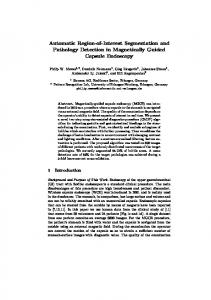
2.1.5 On-the-Fly Training Often, an object boundary may not consist of “strong” edge features. For example, Figure 1(a) shows a CT scan of the heart where the boundary of the left ventricle (labelled) has a low gradient magnitude--especially when compared to the much higher gradient magnitude (right of the ventricle) of the heart‟s nearby outer boundary. As a result, when trying to track the right boundary of the ventricle, the optimal boundary “snaps” to the lower cost outer heart boundary rather than follow the desired higher cost ventricle boundary. Further, since the ventricle boundary‟s gradient magnitude is relatively low (corresponding to
a relatively high static feature cost) then the short, high local cost path that cuts across the upper-left corner of the ventricle produces a cumulative lower cost than the desired longer, slightly lower local cost path around the corner. Both of these problems are resolved when the gradient magnitude feature cost function is determined dynamically from a sample of the desired boundary (static training as applied to boundary finding is introduced in [25]. Training allows dynamic adaptation of certain cost feature functions based on a sample boundary segment. Training is performed dynamically as part of the boundary segmentation process. Trained features are updated interactively as an object boundary is being defined. This eliminates a separate training phase and allows the trained feature cost functions to adapt within the object being segmented as well as between objects in the image. Figure 1(d) demonstrates how training was effective in isolating the weaker left ventricle edge to completely define the ventricle‟s boundary with a single short training segment. To facilitate sampling of edge characteristics, feature value images are precomputed for all trainable features: the three pixel value features, fP, fI, and fO, and the gradient magnitude feature, f'G (where f‟G = G′⁄max G′is simply the scaled gradient magnitude). During training, sampled pixel values from these precomputed feature images are used as indices into the corresponding feature histograms. As such, feature value images are computed by simply scaling and rounding fP, fI, fO, and f'G respectively. Letting IP, II, IO, and IG be the feature value images corresponding to the feature cost functions fP, fI, fO, and f'G, respectively, then IP
( n P 1) f P
II
(n I
IO
(nO 1) f O
0 .5
IG
( nG
0 .5
1) f I 1) f G
0 .5 0 .5
(10)
compute the feature value images where nP, nI , nO = 256 and nG = 1024 are the respective histogram domains (i.e., number of entries or bins). These feature images are sampled to both create dynamic histograms (which are then scaled, weighted, and inverted to create cost maps) and as indices into the dynamic feature cost maps when computing link costs. Selection of a “good” boundary segment for training is made interactively using the live-wire tool. To allow training to adapt to gradual (or smooth) changes in edge characteristics, the trained feature cost functions are based only on the most recent or closest portion of the current defined object boundary. A training length or maximum sample size t, specifies how many of the most recent boundary pixels are used to generate the training statistics.
Figure 1: (a) CT scan of the heart. (b) Untrained live-wire segment (cuts across corner of left ventricle). (c) Short boundary segment and untrained live-wire segment (snaps to the stronger gradient of the outer heart wall). (d) Livewire segments (including closing segment) trained on selected boundary segment. Notice that the short training segment is all that is needed to completely define the left ventricle boundary.
A monotonically decreasing weight function, w, determines the contribution from each of the closest t pixels. The training algorithm samples the precomputed feature value images along the closest t pixels of the edge segment and increments the boundary feature histogram element by the corresponding pixel weight to generate a histogram for each feature involved in training. The training length is typically short (32 to 64 pixels) to allow it to adapt to gradual changes. However, short training segments often result in noisy sampled distributions. Convolving the boundary feature histograms with a 1-D Gaussian helps reduce the effects of noise.
92
IJCA Special Issue on “Recent Trends in Image Processing and Pattern Recognition” RTIPPR, 2010. After sampling and smoothing, each feature histogram is then scaled and inverted to create the feature cost map. A maximum local link cost, M, specifies the largest integer cost possible through summation of feature cost components. Each scaled feature‟s maximum link cost is the product of the feature‟s weight factor, ω, and the maximum link cost value, M. These maximum feature cost values are used as scaling factors when converting the sampled histograms into feature cost maps. Thus, letting hG represent the sampled and smoothed gradient magnitude histogram, the dynamic gradient magnitude cost map, mG, is computed by inverting hG, scaling and rounding as follows: mG
max( hG ) hG MG max( hG )
0.5
MG 1
hG max( hG )
0.5 (11)
where the division by max(hG) scales the histogram between 0 and 1 for further scaling by MG. The same equation is used for the other dynamic feature cost maps, mP, mI , and mO, with appropriate substitutions of hP, hI, and hO for hG and MP, MI, and MO for MG. Notice that no restriction was placed on the size of the minimum sample size s in relation to t; thus, if s > t then the inverse linear ramp is always present, though not dominant, in the cost map. Notice further that if ts = 0 (i.e., no training data is available), then m'G simply produces the unadjusted static gradient magnitude cost function (an inverse linear ramp). Thus, m'G computes both the static and dynamic gradient magnitude cost functions.
2.1.6 Static Neighbourhood Link Cost Since training is not available on the Laplacian zero-crossing and gradient direction features, these costs are precomputed and combined into a static neighbourhood cost map, thereby avoiding expensive cost computations within the interactive live-wire environment. These combined costs are computed for every link by summing the scaled, rounded local static cost functions. Given a point, p, and any neighbouring point, q, the static link cost map, lS, is l S ( p, q)
M Z f Z (q) 0.5
M D f D ( p, q) 0.5
(13)
where MZ and MD are the maximum Laplacian zero-crossing and gradient orientation link cost (similar to MP, MI, MO and MG defined for Eq. (11)). Since there are 8 neighbours for each pixel, the precomputed static link map, lS, requires 8N cost values for N image pixels.
2.1.7 Final Local Link Cost Finally, to compensate for differing distances to a pixel‟s neighbours, gradient magnitude costs are weighted by Euclidean distance. The local gradient magnitude costs to horizontal and vertical neighbours are scaled by 1 ⁄ 2 and to diagonal neighbours by 1. Thus, the weighting function wN for a neighbour q of a pixel p is w N ( p, q )
1; if L x ( p, q) 0 L y ( p, q) 0 1 ; if L x ( p, q) 0 L y ( p, q) 0 2
(14)
where Lx and Ly are horizontal and vertical components of the bidirectional link vector L defined in Eq. (6). the local cost function, l, is a weighted summation of feature cost functions (fZ, fD, fG, etc.) and ranges from 0 to 1. However, we
create an updated local cost function, l´, with an integer range between 0 and M -1 (inclusive) which incorporates training, the precomputed static link map, lS, and the Euclidean distance weighting function. The resulting, updated local cost function, l', for a neighbour q of a pixel p is l ( p, q) l s ( p, q) wN ( p, q) mG ( I G (q)) m P ( I P (q)) m I ( I I (q)) mO ( I O (q))
(15)
where ls is the static link cost in Eq. (13), wN is the neighbourhood weighting function in Eq. (14), each m (or m'G) is the corresponding feature‟s mapping function generated through training as defined in Eq. (11) (or Eq. (12)), and each I is the precomputed feature value image for the corresponding feature (Eq. (10)).
3. UNRESTRICTED GRAPH SEARCH Our graph formulation is pixel based rather than crack based and we utilize a more efficient optimal graph search algorithm based on Dijkstra‟s [1] algorithm. The extensions to the previous optimal graph search boundary finding methods can be given in 3ways: 1) 2)
It imposes no sampling or searching constraints. The active list is sorted with a specialized O(N) bucket sort (where N is number of pixels processed in image).
3)
No a priori goal nodes/pixels are specified.
First, with the exception of [13,14,12], many of the previous boundary finding techniques that utilize graph searching or dynamic programming impose searching and/or sampling constraints to reduce the problem size and/or enforce specific boundary properties. This paper imposes no such constraints, thereby providing object boundaries with greater degrees of freedom and generality. Second, this paper uses discrete local costs within a range. This permits the use of a specialized bin sort algorithm that inserts points into a sorted list (called the active list) in constant time. Finally, since the live-wire tool determines a goal pixel after the fact, the graph search algorithm must compute the optimal path to all pixels since any one of them may subsequently be chosen but this is the key to the interactive nature of the live-wire tool. The graph search algorithm is initialized by placing a start or seed point, s, with a cumulative cost of 0, on an otherwise empty list, L (called the active list). A point, p, is placed on the active list in sorted order based on its total or cumulative cost, g (p). All other points in the image are (effectively) initialized with infinite cost. After initialization, the graph search then iteratively generates a minimum cost spanning tree of the image, based on the local cost function, l'. In each iteration, the point or pixel p with the minimum cumulative cost (i.e., the point at the start of the sorted list) is removed from L and “expanded” by computing the total cost to each of p‟s unexpanded neighbours. For each neighbour q of p, the cumulative cost to q is the sum of the total cost to p plus the local link cost from p to q - that is, gtmp = g(p)+ l'(p, q). If the newly computed total cost to q is less than the previous cost (i.e., if gtmp < g(q) then g(q) is assigned the new, lower cumulative cost and an optimal path pointer is set from q back to p. After computing the cumulative cost to p‟s unexpanded neighbours and setting any necessary optimal path pointers, p is marked as expanded and the process repeats until all the image pixels have been expanded. 93
IJCA Special Issue on “Recent Trends in Image Processing and Pattern Recognition” RTIPPR, 2010. The active list is implemented as an array of sublists where the array size is the range of discrete local costs, M. Each sublist corresponds to points with equal cumulative path cost. As such, the order of points within a sublist is not important and can be arbitrary. Consequently, the sublists are singly linked list implementations of stacks. Let L(i)↓q denote that a point q with cumulative path cost c is added to the active list in sorted order by pushing q onto the stack at list array index i = c mod M. If M is a constant power of 2, the modulo operation can be replaced with a faster bitwise AND operation resulting in i = c AND (M -1). Thus, adding a point to the active list requires one bitwise AND operation to compute the stack index, the corresponding array indexing operation, and then two pointer assignments to push the point on the stack. Let N(p) be the set of pixels neighbouring p and e(p) be a Boolean mapping function indicating that a point p has been expanded. Further, let ptr(q) be the optimal path pointer for the point q, then the unrestricted graph search algorithm is as follows: Algorithm: Input: s, l(p, q) Data Structures: L, N(p), e(p), g(p) Output: ptr Algorithm: g(s)=0; L(0) s While L do begin p min(L); e(p)=TRUE; for each q N(p) such that not e(q) do begin gtmp= g(p)+l‟(p,q); if q L and gtmp