Segmentation of building models from dense 3D point-clouds Joachim Bauer∗, Konrad Karner∗, Konrad Schindler†, Andreas Klaus∗, Christopher Zach∗ ∗ †
VRVis Research Center for Virtual Reality and Visualization,
Institute for Computer Graphics and Vision, Graz University of
Technology {bauer,karner,klaus,zach}@vrvis.at,
[email protected]
Abstract: This paper proposes an approach for the detection and partition of planar structures in dense 3D point clouds from facades. The aim is the creation of a polygonal model with a considerably lower complexity than the original data set. We perform a robust detection of the dominant facade planes and apply a sweep based scheme in order to detect structures like windows, doors, balconies in those planes.
1
Introduction
In the field of city modeling a crucial step is the creation of models with a preferably low-polygon count. Image-based methods were proposed by Zisserman et. al. [8] where planes are detected by an sweeping method and Teller et. al. [7] where also microstructures in the facade plane are extracted. Another approach is the use of dense 3D point clouds resulting from image matching for the modeling. Those point clouds should be transferred into a low-polygon representation while still preserving fine detail e.g. edges. Proposed methods vary from general methods [1] and [3], which do not consider the specific demands on building model simplification approaches, to very problem specific approaches [4]. When dealing with buildings the most prominent features are facade planes and in those planes the indents from windows, doors etc. and protrusions created e.g. by balconies and friezes. We report on a system for creating plane based models of buildings from dense 3D point clouds resulting from dense 3D point clouds. Those point clouds are the result of dense image matching process applied on multiple images with known orientation. In our approach we extract the main facade planes and perform a partition of those planes into a set of orthogonal polygons (w.r.t. the facade plane boundaries) using a sweep based algorithm. Additionally required source data are a sequence of images (at least one image is needed) with known exterior and interior orientation and the vanishing points detected in the images. For the 3D point cloud all dominant facade planes are
detected with a RANSAC-based method. A sweep-based partitioning approach divides each plane into a set of rectangular polygons. The polygons are validated using a point-density criterion.
2
Segmentation
For the segmentation approach a set of images with known exterior and interior orientation together with a dense 3D point cloud are the input data. Optionally 3D lines, generated by the line matching approach from [6], can be used to improve the segmentation accuracy. 2.1
Plane detection
The following method is employed to detect 3D planes in the 3D point cloud: 1. randomly choose a seed point from the point cloud (this is comparable to a bucketing approach); 2. perform a RANSAC based plane detection algorithm in a local neighborhood around the seed point (a KD-tree is used for fast nearest neighbor queries); 3. verify the resulting local plane hypothesis; 4. refine the local RANSAC solution with an iterative least squares fit using the whole point cloud; 5. repeat from step 1 until no new planes are found; The iterative refinement of the detected RANSAC plane hypothesis uses only those inlier points that form a densely connected set. The largest connected set is found by recursively searching the inlier point cloud from different seed points. This approach minimizes the influence of points that belong to other closely adjacent planes or coplanar but distant planes. Finally the planes that share too many mutual inliers are rejected. The detection method is comparable to the approach of Danuser and Stricker [2] and yields a set of accurate 3D planes. 2.2
Plane partition
After the segmentation process the particular 3D planes are partitioned into sets of rectangular polygons based on their support from the 3D point cloud. Based on the assumption, that for many buildings most of the prominent features in the facade plane e.g. windows, doors etc. are axis-aligned with the facade boundary and rectangular, we apply a sweeping process to compute partition hypotheses. The process can be divided into four steps:
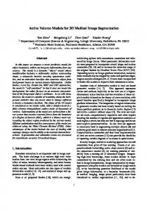
1. collection of inlier points w.r.t. one plane (based on a distance threshold) 2. rejection of inlier points that are not belonging to the largest connected set (see 2.1); 3. project remaining inlier points into one image; 4. generate partition hypotheses by sweeping using the vanishing points; 5. validation of polygon hypotheses resulting from the sweeping (using a point density threshold); In the first step the inlier points for one plane are collected and projected into one image. This is necessary to have a relation between the 3D points and the vanishing points and also provides a homogeneous density of the 3D points, since the images were used in the matching process. Figure 1(a) shows the projected inlier points for a facade plane. Figure 1(b) shows a detailed view. For indentations or protrusions created by typical features such as windows, balconies, friezes etc. that are not coplanar with the main facade plane the density of the projected inlier points changes significantly (see Figure 1).
(a)
(b)
Figure 1: Sweep based segmentation: (a) The projected inlier points for the facade plane are shown in red, the vanishing lines that are bounding the point set are shown in red and blue respectively. The sweep line originating from the vertical vanishing point is shown in yellow. (b) Close up view to show density differences.
The basic idea for the sweep based segmentation for architectural scenes is that only 3D points lying on one plane are projected into the image. For all other regions lying behind or in front of the facade
plane e.g. windows or balconies the density of inlier points is significantly lower (see figure 1(b)). This changes in density are detected by the following sweeping process: 1. compute the convex hull of projected 3D plane points in the image; 2. determine the two vanishing points with the method of Rother [5] (one vertical and one horizontal vanishing point) for the facade plane; 3. instantiate a sweep line for each of the two vanishing points (one end of the sweep line is fixed at the respective vanishing point - see Figure 2); 4. sweep line over the convex hull containing the inlier points of the facade plane and record significant changes in the point density on the opposite sides of the sweep line; For the efficient sweeping a KD-tree optimized for 2D-line queries is used. During the sweeping a local neighborhood around the sweep line, i.e. points within a certain perpendicular distance from the line, is used to detect density changes. The density is recorded as the difference between the number of points on the opposite sides of the sweep line. An improvement is the weighting of the point count with the perpendicular distance of the points from the sweep line i.e. points that are farther from the sweep line contribute less to the computed density value. These differences between points counts on the two sides of the sweep line are used to detect partition line hypotheses - at sweep positions where the density difference has a local maximum a partition line is instantiated. Additional 3D features e.g. 3D lines can also be integrated - if the
Figure 2: Schematic sketch of the sweeping process for the horizontal vanishing point: the convex hull of the projected inlier points of the plane is shown as dotted outline, the boundaries of the sweep range are dashed and the sweep line is solid.
projection of the line points to a vanishing point it provides a good cue for a partition line. The intersecting points of the hypothetical partition lines resulting from sweeps of two different vanishing points of a plane form hypothetical polygons (see Figure 3). In order to select valid polygons the number of inlier points weighted with the polygons area is used. The 3D coordinates of the polygons are computed by intersection of the ray (created by the 2D intersection and the camera origin) with the 3D plane. Figure 3 shows the detected polygons for the two facade planes.
(a)
(b)
Figure 3: Segmentation result: (a) Intersecting lines from two vanishing points (blue and green) form polygons. The polygons are perspectively disorted in the image but rectangular in 3D. (b) Visualization of valid polygons. The texture has been undistorted to correct for projective distortion.
3
Conclusion
The presented method yields promising results, though some improvements seem to be necessary in order to increase the segmentation accuracy. For regions inside the facade plane that are not coplanar with the facade plane and therefore appear as ’hole’ in the model the geometry can be reconstructed using a Delaunay triangulation on the original 3D points. The advantages of our approach are listed below: • extraction of a low-polygon count model from dense 3D point clouds; • ’smoothed’ edges in the point cloud are recovered and ’sharpened’; • image texture for the polygons can be easily extracted; • additional 3D features such as the 3D points that are reconstructed during the image orienta-
tion process and 3D lines can easily be incorporated in the sweeping algorithm;
Acknowledgments This work has been done in the VRVis research center, Graz and Vienna/Austria (http://www.vrvis.at), which is partly funded by the Austrian government research program Kplus.
References [1] C. Andujar, P. Brunet, and D. Ayala. Topology-reducing surface simplification using a discrete solid representation. ACM Transactions on Graphics, 21(2), 2002. [2] G. Danuser and M. Stricker. Parametric model fitting: from inlier characterization to outlier detection. IEEE Transactions on Pattern Analysis and Machine Intelligence, 20(3), 1998. [3] M. Garland and P. S. Heckbert. Surface simplification using quadric error metrics. In Proceedings of SIGGRAPH ’97, pages 209–216, 1997. [4] H. Mayer. Scale-space events for the generalization of 3D-building data. International Archives of Photogrammetry and Remote Sensing, 33(Part B 4/2):639–646, 2000. [5] C. Rother. A new approach for vanishing point detection in architectural environments. In Prodeedings of the 11th British Machine Vision Conference, pages 382–391, 2000. [6] C. Schmid and A. Zisserman. The geometry and matching of lines and curves over multiple views. IJCV, 40(3):199– 233, December 2000. [7] Seth Teller, Xiaoguang Wang, Stefano Totaro, Franck Taillandier, and Allen Hanson. Recovering facade texture and microstructure from real-world images. In Proceedings, ISPRS Commission III Symposium on Photogrammetric Computer Vision, pages 381–386, 2002. [8] A. Zisserman, T. Werner, and F. Schaffalitzky. Towards automated reconstruction of architectural scenes from multiple images. In Proc. 25th workshop of the Austrian Association for Pattern Recognition, pages 9–23, 2001.