Abdulhameed Abdullah Yaseen, David Begg, and Nikos Nanos. AbstractâThe collapse of building structures during recent earthquakes, particularly in the ...
International Journal of Structural Analysis & Design– IJSAD Volume 2: Issue 1 [ISSN : 2372-4102] Publication Date : 30 April, 2015
Seismic fragility assessment of low-rise unreinforced masonry buildings in the Kurdistan region of Iraq Abdulhameed Abdullah Yaseen, David Begg, and Nikos Nanos paper investigates the fragility of existing unreinforced masonry buildings in the KR using an analytical approach. Two typical URM buildings, which represent the typical oneand two-storey residential buildings in urban areas and constitute approximately 87% of the buildings in the region [7], were considered in this study. The one- and two-storey buildings are 3.0 and 6.0 m high, respectively, with plan dimensions of 15 × 10 m (Fig. 2). The fundamental construction materials of the masonry walls and slabs are solid concrete blocks and reinforced concrete, respectively.
Abstract—The collapse of building structures during recent earthquakes, particularly in the countries around the Kurdistan region (KR), such as Turkey (2011 Van earthquake) and Iran (2003 Bam earthquake), has raised many questions about the safety of existing buildings in the region and those structures that are going to be constructed in the future. The KR, which is located in the north and northeastern parts of Iraq, is also considered to be the most hazardous part of Iraq. However, many buildings in the region, especially the unreinforced masonry buildings, were not engineered to withstand seismic loads. This paper investigates the seismic fragility of existing unreinforced masonry buildings in KR in terms of their fragility curve and surface using an analytical approach. This study considers many factors, including the variability of the mechanical properties of materials, ground motion intensity measures (IMs), a number of ground motion records and their effect on the selection of IMs and thus the derivation of the fragility curves. The results demonstrate that unreinforced masonry low-rise buildings in the KR are highly vulnerable to seismic loads and that such structures must be strengthened to prevent failure.
This study uses incremental dynamic analysis (IDA) [8] to consider the nonlinearity behaviour of URM buildings and estimate their performance under seismic loads more thoroughly. In this approach, several ground-motion time histories are scaled to several levels of intensity and then applied to the structural model using the TREMURI software [9]. Different sets of records (e.g., sets 7, 15, 35/38 and 12, 25, 60 records) are selected and scaled to 8 levels of PGA (e.g., 0.02 g, 0.05 g, 0.1 g, 0.2 g, 0.4 g, 0.6 g, 0.8 g, and 1.0 g). To select the time histories, a substantial number of available response spectra records obtained from PEER NGA [10] are scaled to match the following four target spectra, defined by the seismic characteristics of the KR given in Table 1: (1) the target response spectra proposed for the KR, which are relevant to the two proposed seismic hazard zones “B” and “A”, which are representative of areas with “high” to “very high” levels of earthquake risk, respectively, as shown in Fig. 2; (2) the target response spectra defined by seismic design code EC8; (3) the conditional mean spectrum CMS [11]; and (4) an algorithm proposed by Jayaram et al. [12] for matching records to the mean and variance of a target response spectrum. The details of creating a seismic hazard zone map and developing the target response spectra for the KR are not provided here because it is beyond of the scope of this paper. The four aforementioned ground motion selection and modification (GMSM) methods are also used to examine the effects of the earthquake record selection method on the results of time history analyses and derived fragility curves and surfaces. Based on the type of time history, 36 ground motion intensity measures (IMs) for each record are defined to be used as indices of the damage potential of ground motion (Table 2).
Keywords—fragility curve, fragility surface, ground motion, unreinforced masonry building
I.
Introduction
The Kurdistan region (KR) has a population of approximately 5 million people and is located in the north and northeastern parts of Iraq; it is considered the most seismically hazardous part of Iraq. Because of its location (Fig. 1) in a relatively active seismic zone (i.e., it borders the ZagrosTauros Belt), where the Arabian, Eurasian, and Anatolian tectonic plates collide [1], Ameer et al. [2] asserted that destructive earthquakes are widely expected in this part of Iraq (i.e., the KR) in the future. The maximum expected earthquake magnitude Mmax in the KR is 7.68 ± 0.52 [2]. The most recently recorded moderately devastating earthquake was M s 5.1 (Mw 5.5), which occurred at a focal depth of 26 km and a distance of 37.2 km from the regional capital city of Erbil on July 24, 1991. Approximately twenty people were killed, and several houses either collapsed or were damaged [3]. Aziz et al. [4] stated that seismic activity has increased in the region over the last decade. Thus, assessing the seismic vulnerability of the built environment of the KR is essential for predicting loss assessments and identifying the most vulnerable structures in the region. With the knowledge that 75% of casualties caused by earthquakes are caused by the collapse of buildings [5] and that the unreinforced masonry (URM) buildings present the greatest vulnerability [6], the present
Defining an indicator to represent the damage level of a structure caused by an earthquake is another main factor that should be considered when performing a fragility analysis. In this study, the limit states defined by Milutinovic and Trendafiloski [13] are considered (see Table 3). However, as proposed by the recent studies of Crowley et al. [14] and Gehl et al. [15], the number of damage state limits was reduced from five to two levels by merging the damage states from “slight” to “extensive” into a state called “Yield,” and the damage states of “very heavy” and “collapse” into a state
Abdulhameed Abdullah Yaseen, David Begg, and Nikos Nanos School of Civil Engineering and Surveying, University of Portsmouth United Kingdom
1
International Journal of Structural Analysis & Design– IJSAD Volume 2: Issue 1 [ISSN : 2372-4102] Publication Date : 30 April, 2015 called “Collapse”. The Collapse state is a level at which repairing of the building is not practical or possible, whereas a Yield-state structure can be used if suitable repair is completed. The yield displacement (dy) and ultimate displacement (du) values, which are required by this criterion, are obtained by a pushover analysis of the buildings using the TREMURI software.
IMs Displacement-based
𝑃𝐹 =
Duration
𝑃𝐹 =
TABLE III.
Damage state
(1)
1 1 + 𝑒 −𝛽1 −𝛽2 .𝐿𝑛
𝐼𝑀1 −𝛽3 .𝐿𝑛(𝐼𝑀2 )
(2)
Here β1, β2 and β3 are obtained from a regression analysis of the results, including the variation of IMs. The Collapse damage state is defined using the above-mentioned equations; then, the Yield damage state can be obtained as follows: PYield = 1- PCollapse
Mag.
PGA (g)
Focal Depth (km)
Vs30 (m/s)
EC8 Site Class
A
5.4-7.7
> 0.4
< 35
> 400
B
B
5.1-7.5
0.250.4
< 60
> 200
B&C
Acceleration-based
Velocity-based
Limit for d (mm) Two-storey
0.51
1.42
Moderate
d = 0.7dy +0.05(0.9du −0.7dy)
1.34
2.55
Extensive
d = 0.7dy +0.2(0.9du −0.7dy)
3.83
5.93
Very heavy
d = 0.7dy +0.5(0.9du −0.7dy)
8.79
12.7
Collapse
d = 0.9du
17.1
26.64
Results
Variability in material properties
The variability in material properties is obtained by running approximately 1,100 time history analyses applied to a one-storey building in the X-direction by using a fixed accelerogram scaled to three PGA intensities (e.g., 0.05 g, 0.2 g, and 0.8 g). For each intensity level, a set of variants is assigned with respect to the different material properties, as shown in Table 4. A second set of analyses is carried out considering the variability due to ground motions and neglecting the variability induced by the material properties. Variability in ground motions is calculated by fixing the mean values of the material properties. The two standard deviations of the results in terms of the top displacement related to the ground motion and the material parameters variability are calculated. Then, for each considered PGA level (e.g., 0.05 g, 0.2 g, and 0.8 g), the total standard deviation is calculated as the square root of the sum of the squares of the two aforementioned standard deviations. The results obtained demonstrate that the effect of the variability in ground motion is more important than that of the material properties, especially for medium to high levels of PGA, as shown in Fig. 3. Thus, the variability in material parameters is neglected, and the mean values of the masonry material properties (e.g., Young’s modulus Em=4,350 N/mm2, shear modulus G=0.4E, specific weight w=21 kN/m3) are considered for the remainder of this study.
Fault Mechanism Thr./Rev., S.S., Nor.a Thr./Rev., S.S., Nor.
GROUND-MOTION IMS CONSIDERED IN THE CURRENT STUDY.
IMs
Limit for d (mm) One-storey
d = 0.7dy
A.
a. Thr.: Thrust; Rev.: Reverse; S.S.: Strike Slip; and Nor.: Normal
TABLE II.
Limit-displacement equation
II.
SEISMIC CHARACTERISTICS OF SEISMIC HAZARD ZONES A AND B
Zone
PERFORMANCE LEVELS FOR URM BUILDINGS PROPOSED BY MILUTINOVIC AND TRENDAFILOSKI [13]
Slight
(3)
The accuracy of the information used in the fragility assessment of buildings is crucial in reducing the uncertainties involved in that process. The following three main sources of these uncertainties are considered in this study: the variability in the mechanical properties of the target buildings versus ground motions, variability in the ground motion intensity measurements, and variability in the number of records and the way of selecting these records. TABLE I.
Predominant period (Tp) and mean period (Tm)
Note: refer to Kramer [16] for the explicit explanation of the IMs examined.
1 1 + 𝑒 −𝛽1 −𝛽2 .𝐿𝑛(𝐼𝑀)
PGV/PGA, PGA/PGV, and PGV2/PGA
Hybrid
Finally, to derive the fragility curves and surfaces, a loglog regression function is used to fit the data. Equations 1 and 2 are used to find the probability of failure, P F, of the fragility curve and surface, respectively, as follows:
Name Peak ground displacement (PGD), root mean square of displacement (DRMS), spectral displacement at different periods Sd(nT1), where n=1, 2, 3, 4, 8, 16, 32 and T1 is the fundamental period of the structure
Name Peak ground acceleration (PGA), root mean square of acceleration (ARMS), Arias intensity (IA), characteristic intensity (IC), cumulative absolute velocity (CAV), acceleration spectrum intensity (ASI), sustained maximum acceleration (SMA), effective design acceleration (EDA), A95 parameter, and spectral acceleration at different periods Sa(nT1), where n=1, 2, 3, 4, 8, 16, 32 and T1 is the fundamental period of the structure Peak ground velocity (PGV), root mean square of velocity (VRMS), specific energy density (SED), velocity spectrum intensity (VSI), sustained maximum velocity (SMV), and Housner intensity (IH)
B.
Fragility curves and selection of the best IMs
The variability in the number of records (e.g., sets of 7, 15, 35/38 records as well as sets of 12, 25 and 60 records) and the method of selecting these records (e.g., CMS, the Jayaram et
2
International Journal of Structural Analysis & Design– IJSAD Volume 2: Issue 1 [ISSN : 2372-4102] Publication Date : 30 April, 2015 al. algorithm, target spectra defined by EC8, and target spectra proposed for the KR) are considered for both the one- and two-storey buildings located in seismic hazard zones A and B. In total, approximately 1,140 time history analyses are performed for both types of buildings (i.e., approximately 570 time histories for each building located in zones A and B). Fragility curves are developed for all aforementioned scenarios using Equation 1 and with respect to the IMs selected from cluster 1, as shown in Table 5. Using Tanagra software [17] and the VARCLUS procedure, the 36 IMs are merged into two clusters, and for all sets of earthquake records, the correlation between these two clusters and the buildings’ responses demonstrate that relevant ground parameters are to be selected from cluster 1, whereas cluster 2 is poorly correlated to the structural response. As an example, table 5 presents the correlation coefficients between these two clusters and the drift obtained from the simulations using a set of 60 earthquake records.
TABLE V. CLUSTERS GENERATED FROM THE ACCELEROGRAM DATASET AND THE CORRESPONDING GROUND-MOTION PARAMETERS. THE CORRELATION COEFFICIENTS BETWEEN THESE VALUES AND THE DRIFT WERE OBTAINED FROM THE SIMULATIONS USING A SET OF 60 EARTHQUAKE RECORDS.
The graphical representation of the fragility curves demonstrates that ASI has the smallest dispersion in nearly all cases considered for a one-storey building because the slope of its relevant fragility curves is steeper than that of the other IMs. Furthermore, ASI is less sensitive to the number of records and is less affected by the different ground motion selection methods used in the study. However, VSI with less uncertainty (i.e., steeper slope of its fragility curve) is the best ground motion parameter for deriving fragility curves for the two-storey buildings. Figures 4 and 5 present the collapse fragility curves derived for one- and two-storey buildings located in zone B, respectively. Because of space constraints, only the results of zone B are presented.
C.
Cluster
1
2
RANGE OF VALUES CONSIDERED FOR DIFFERENT MECHANICAL PARAMETERS OF MASONRY Shear ultimate drift ratio %
Rocking ultimate drift ratio %
2700-6000
0.15, 0.25, 0.35
18, 20, 22
0.4, 0.6, 0.8
0.6-1.0
0.88
0.91
0.26
0.27
Fragility surface
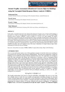
The results obtained demonstrate that low-rise URM buildings in the KR are highly vulnerable to seismic loads. As shown in Figures 6 and 7, the Collapse probability failure for one- and two-storey buildings caused by an earthquake with PGA=0.42 g (e.g., 1994 Northridge-01, M=6.69, EpiD=13.39 km, ASI=3.47 m/s, and VSI=266.29 cm), for example, is 0.23 and 0.96, respectively, and the Yield probability failure is 0.77 and 0.04, respectively.
TABLE IV.
Specific weight (kN/m3)
Top displacement (two-storey building)
Using Equation 2 and parameters ASI and VSI, the fragility surfaces for the one- and two-storey buildings are developed and shown in Figures 6 and 7 using a set of 60 records. The scatter in the results is shown by plotting a single parameter fragility curve (i.e., the ASI fragility curve) against slices of the fragility surface at different levels of the second parameter VSI. Fragility curves can only estimate the response of structures that have a similar fragility surface, with VSI=180 cm in two-storey buildings and VSI=250 cm in onestorey buildings. Otherwise, the results will be underestimated or overestimated based on the different levels of VSI. Hence, two parameters should be used instead of one to represent the seismic action of a given region.
Furthermore, as shown in Figures 4 and 5, the use of incremental dynamic analysis and a well-selected IM allow fragility curves to be derived from even a small number of records (a minimum of 7 records is used as an example) with the same performance as for a large number of records (i.e., 38 records for example). Additionally, correct selection of ground motion IM can eliminate the ground motion selection method’s effect on the results (see Figures 4 and 5). Therefore, it can be concluded that correctly selecting an IM takes priority over other variabilities considered in this study when deriving fragility curves.
Shear resistance (N/mm2)
PGA, PGV, PGD, PGV/PGA, PGA/PGV, PGV2/PGA, ARMS, VRMS, DRMS, IA, IC, SED, CAV, ASI, VSI, IH, SMA, SMV, EDA, A95 Sa T1, Sa 2T1, Sa 3T1, Sa 4T1, Sa 8T1, Sa 16T1, Sa 32T1, Sd T1, Sd 2T1, Sd 3T1, Sd 4T1, Sd 8T1, Sd 16T1, Sd 32T1, Tp, Tm
Top displacement (one-storey building)
To check the efficiency of using two ground motion parameters (i.e., the fragility surface) instead of using one parameter (i.e., the fragility curve), as suggested by several studies (e.g., Baker and Cornell [18]; Kafali and Grigoriu [19]; Seyedi et al.[20]), different pairs of parameters, such as PGVPGA/PGV, PGA-PGV2/PGA, EDA- PGV2/PGA, ASI-VSI, EDA-VSI, and PGA-VSI, are compared in terms of their ability to accurately predict the response of buildings. The results demonstrate that all of the considered pairs of IMs can predict the response of buildings with a high rate of accuracy. However, the pair ASI-VSI predicts the building response more accurately than the other pairs in most cases because it provides a correlation measure Nagelkerke R2 [21] closer to 1. Tables 6 and 7 present the results for one- and two-storey buildings, respectively, located in zone B using different sets of earthquake records as examples.
The selection of ASI and VSI parameters can be explained by the fact that these parameters consider the spectral acceleration for ASI and the spectral velocity for VSI over a wide range of periods (e.g., 0.1-0.5 s for ASI and 0.1-2.5 s for VSI). This range can explain the possibility of the increase in the natural period of the buildings due to a loss of rigidity and the progressive degradation produced in the buildings considered in this study.
Modulus of elasticity of masonry (N/mm2)
Ground-motion parameters
3
International Journal of Structural Analysis & Design– IJSAD Volume 2: Issue 1 [ISSN : 2372-4102] Publication Date : 30 April, 2015 TABLE VI.
2
PERCENTAGE CORRECT AND NEGELKERKE R VALUES FOR PREDICTED RESPONSES OF A ONE-STOREY BUILDING IN ZONE B USING DIFFERENT SETS OF RECORDS AND TWO GROUND MOTION PARAMETERS
One-storey (Zone B) Ground-motion intensity measures IM1
35 records
15 records-CMS
15 recordsJayaram et al.
15 records-EC8
15 recordsPro. response spectrum for KR
7 records
Percentage Correct
Nagelkerke
Percentage Correct
Nagelkerke
R2
Percentage Correct
Nagelkerke
R2
Percentage Correct
Nagelkerke
R2
Percentage Correct
Nagelkerke
R2
Percentage Correct
Nagelkerke
R2
2
IM2
R2
PGA PGA PGA
PGV /PGA ASI VSI
92.7 92.1 93.9
0.833 0.829 0.857
95.3 92.2 96.9
0.897 0.906 0.963
93.4 93.4 95.1
0.910 0.904 0.902
91.9 95.2 91.9
0.833 0.868 0.869
88.7 91.9 91.9
0.810 0.877 0.836
96.4 96.4 100.0
0.934 0.945 1.000
EDA EDA EDA ASI PGV
PGV /PGA ASI VSI VSI PGA/PGV
2
92.7 92.7 93.3 94.5 92.7
0.842 0.819 0.871 0.880 0.830
93.8 93.8 93.8 93.8 95.3
0.878 0.879 0.920 0.916 0.878
93.4 95.1 93.4 95.1 93.4
0.904 0.930 0.907 0.904 0.905
91.9 95.2 91.9 98.4 91.9
0.817 0.858 0.863 0.946 0.832
90.3 95.2 93.5 95.2 88.7
0.858 0.915 0.916 0.921 0.808
96.4 100.0 92.9 100.0 100.0
0.874 1.000 0.888 1.000 1.000
TABLE VII.
PERCENTAGE CORRECT AND NEGELKERKE R2 VALUES FOR PREDICTED RESPONSE OF A TWO-STOREY BUILDING IN ZONE B USING DIFFERENT SETS OF RECORDS AND TWO GROUND MOTION PARAMETERS
Two-storey (Zone B) Ground-motion intensity measures IM1
35 records
15 records-CMS
15 recordsJayaram et al.
15 records-EC8
15 recordsPro. response spectrum for KR
7 records
Percentage Correct
Nagelkerke
Percentage Correct
Nagelkerke
R2
Percentage Correct
Nagelkerke
R2
Percentage Correct
Nagelkerke
R2
Percentage Correct
Nagelkerke
R2
Percentage Correct
Nagelkerke
R2
2
IM2
R2
PGA PGA PGA
PGV /PGA ASI VSI
93.5 91.4 96.2
0.877 0.809 0.915
94.3 94.3 94.3
0.843 0.857 0.905
94.4 95.8 100.0
0.925 0.909 1.000
93.2 93.2 100.0
0.880 0.813 1.000
94.3 92.9 97.1
0.875 0.841 0.948
96.9 96.9 100.0
0.924 0.935 1.000
EDA EDA EDA ASI PGV
PGV /PGA ASI VSI VSI PGA/PGV
2
92.5 88.2 94.1 96.8 93.5
0.854 0.777 0.905 0.930 0.876
92.9 94.3 94.3 95.7 94.3
0.852 0.855 0.902 0.912 0.841
93.0 94.4 100.0 98.6 94.4
0.902 0.893 1.000 0.953 0.924
93.2 91.8 100.0 98.6 93.2
0.864 0.801 1.000 0.957 0.880
94.3 90.0 97.1 97.1 94.3
0.845 0.828 0.948 0.953 0.875
100.0 100.0 100.0 100.0 100.0
1.000 1.000 1.000 1.000 1.000
III.
the results obtained in this study to different types of buildings and materials, different GMSMs, different seismic hazard zones, different numbers of stories, and different numbers of records.
Conclusion
The results obtained demonstrate that low-rise URM buildings in the KR are highly vulnerable to seismic loads and that existing buildings should be strengthened. With regard to the uncertainties in the results, the correct selection of an IM has priority over other variabilities involved in assessing the fragility of URM buildings. Use of IDA and a well-selected IM allow fragility curves to be derived with even a small number of records (i.e., minimum 7 records) with the same performance as for a large number of records (i.e., 60 records). This conclusion is also supported by Gehl et al. [22], who stated that “a relatively small error is introduced into the final results by the limited number of analyses usually used” in developing fragility curves using a non-linear dynamic analysis method. Furthermore, the variability in the mechanical parameters of materials can be neglected because the variability in ground motion is considerably more significant. This result is in agreement with Rota et al. [23], who stated that the variability associated with different values of material parameters can be neglected and that ground motion variability is more significant. The significant difference in the results between using only one IM and using two IMs cannot be ignored; the use of two parameters instead of one is highly recommended when representing the seismic action of a given region. Further research is required to extend
Acknowledgments The authors would like to thank Jayaram et al. for providing the MATLAB implementation of the proposed ground-motion selection algorithm, which is available at http://www.stanford.edu/~bakerjw/gm_selection.html. The authors are also grateful to the TREMURI staff for providing the academic and commercial versions of the TREMURI software, which were used in the example analyses.
References [1]
[2]
[3]
4
R. Gok, H. Mahdi, H. Al-Shukri, and A. J. Rodgers, “Crustal Structure of Iraq from Receiver Functions and Surface Wave Dispersion,” Geophys. Journal Int., Vol 172, pp. 1179-1187, 2006. S. A. Ameer, M. L. Sharma, H. R. Wason, and S. A. Alsinawi, “Probabilistic seismic hazard assessment for Iraq using complete earthquake catalogue files,” Pure Appl. Geophy, Vol. 162, pp. 951-966, 2005. T. Utsu, “42 A list of deadly earthquakes in the world: 1500–2000,” International Geophysics, Vol. 81, pp. 691-XVII, 2002.
International Journal of Structural Analysis & Design– IJSAD Volume 2: Issue 1 [ISSN : 2372-4102] Publication Date : 30 April, 2015 B. K. Aziz, F. A. A. Lawa, and B. M. Said, “Sulaimani seismic swarm during spring 1999, NE Iraq,” Journal of Zankoy Sulaimani, Vol. 4, pp. 87-100, 2001. [5] A. Coburn and R. Spence, Earthquake Protection, 2nd ed., Chichester: John Wiley & Sons, Ltd., 2002. [6] G. Grünthal, European Macroseismic Scale, Luxembourg: Centre Européen de Géodynamique et de Séismologie, 1998. [7] Central Statistical Organization, “Buildings, Dwelling and Establishment Census and households listing. Enumeration and listing report (Report No. 1, Buildings, Dwelling and Households- National level),” Baghdad: CSO, 2011. [8] D. Vamvatsikos and C. A. Cornell, “Incremental dynamic analysis,” Earthquake Engineering & Structural Dynamics, Vol. 31, pp. 491-514, 2002. [9] S. Lagomarsino, A. Penna, and A. Galasco, TREMURI program: Seismic analysis program for 3D masonry buildings. University of Genoa, 2006. [10] B. Chiou, R. Darragh, N. Gregor, and W. Silva, “NGA project strongmotion database,” Earthquake Spectra, Vol. 24, pp. 23-44, 2008. [11] J. W. Baker, “Conditional Mean Spectrum: Tool for ground-motion [4]
selection,” Journal of Structural Engineering, Vol. 137, pp. 322-331, 2011. [12] N. Jayaram, T. Lin, and JW. Baker, “ A computationally efficient ground-motion selection algorithm for matching a target response
[13]
[14]
[15]
[16] [17]
[18]
[19]
[20]
[21] [22]
[23]
[24]
spectrum mean and variance,” Earthquake Spectra, Vol. 27, pp. 797815, 2011. Z. V. Milutinovic and G. S. Trendafiloski, “WP4: Vulnerability of current buildings,” RISK-UE project of the EC: an advanced approach to earthquake risk scenarios with applications to different European towns , 2003. H. Crowley, M. Colombi, V. Silva, N. Ahmad, M. Fardis, G. Tsionis, A. Papailia et al., Fragility functions for common RC building types in Europe, Vol. 3. Tech. Rep, 2011. P. Gehl, D. M. Seyedi, and J. Douglas, “Vector-valued fragility functions for seismic risk evaluation,” Bulletin of Earthquake Engineering, Vol. 11, pp. 365-384, 2013. S. L. Kramer, Geotechnical earthquake engineering, Upper Saddle River, New Jersey: Prentice Hall, 1996. R. Rakotomalala, Tanagra: Un logiciel gratuit pour l’enseignement et la recherche. In:5`emes Journes d’Extraction et Gestion des Connaissances (EGC-2005), pp 697–702, 2005. J. W. Baker and C. A. Cornell, “A vector ‐ valued ground motion intensity measure consisting of spectral acceleration and epsilon,” Earthquake Engineering & Structural Dynamics, Vol. 34, pp. 11931217, 2005. C. Kafali, M. Grigoriu, “Seismic fragility analysis: application to simple linear and nonlinear systems,” Earthquake Engineering and Structural Dynamics,Vol. 36, pp. 1885-1900, 2007. D. M. Seyedi, P. Gehl, J. Douglas, L. Davenne, N. Mezher, and S. Ghavamian, “Development of seismic fragility surfaces for reinforced concrete buildings by means of nonlinear time ‐ history analysis,” Earthquake Engineering & Structural Dynamics, Vol. 39, pp. 91-108, 2010. N. Nagelkerke, “A note on a general definition of the coefficient of determination,” Biometrika, Vol. 78, pp. 691-692, 1991. P. Gehl, J. Douglas, D. Seyedi, “Influence of the number of dynamic analyses on the accuracy of structural response estimates,” Earthquake Spectra, doi:10.1193/102912EQS320M, 2014. M. Rota, A. Penna, and G. Magenes, “A methodology for deriving analytical fragility curves for masonry buildings based on stochastic nonlinear analyses,” Engineering Structures, Vol. 32, pp. 1312-1323, 2010. R. Sorkhabi, “Iraq: The Petroleum Resource Base,” Geo Expro, Vol. 6, pp. 28-34.
Figure 1. (Top) Plate tectonic setting of Iraq showing fault systems and the KR (from [24]); Proposed seismic hazard map of the KR (left bottom); Proposed response spectra for the KR (right bottom)
5
International Journal of Structural Analysis & Design– IJSAD Volume 2: Issue 1 [ISSN : 2372-4102] Publication Date : 30 April, 2015
Figure 2. Distribution of conventional buildings in the KR according to: the construction year and number of floors (left top); and the construction year and type of materials used in external walls (left bottom); 3D view of the two-storey building (right top) and one-storey building (right bottom) under consideration using TREMURI software
Figure 3.
Comparison of the standard deviations obtained from the variability in material properties and ground motions for different levels of PGA.
6
International Journal of Structural Analysis & Design– IJSAD Volume 2: Issue 1 [ISSN : 2372-4102] Publication Date : 30 April, 2015
Figure 4.
Collapse fragility curves for a one-storey building in zone B; vertical dashed lines show the boundary between the damaged and undamaged zones, and the star marks show several values of the observed probability of failure taken as examples for each IM
7
International Journal of Structural Analysis & Design– IJSAD Volume 2: Issue 1 [ISSN : 2372-4102] Publication Date : 30 April, 2015
Figure 5.
Collapse fragility curves for a two-storey building in zone B; vertical dashed lines show the boundary between damaged and undamaged zones, and the star marks show several values of the observed probability of failure taken as examples for each IM
8
International Journal of Structural Analysis & Design– IJSAD Volume 2: Issue 1 [ISSN : 2372-4102] Publication Date : 30 April, 2015
Figure 6.
Figure 7. Fragility surface derived for a two-storey building using a set of 60 records
Fragility surface derived for a one-storey building using a set of 60 records
About Author (s): MR ABDULHAMEED ABDULLAH YASEEN
Qualifications: BSc, MSc Role Title: Research Student Mobile: +44 (742) 7664448 Address: School of Civil Engineering & Surveying, Faculty of Technology, University of Portsmouth, UK
DR DAVID BEGG
Qualifications: BSc, PhD, M.ASCE Role Title: Senior Lecturer Address: Portland Building, Portland Street, Portsmouth (UK) PO1 3AH Address: School of Civil Engineering & Surveying, Faculty of Technology, University of Portsmouth, UK
DR NIKOS NANOS
Qualifications: BEng, MS, PhD Role Title: Lecturer Address: Portland Building, Portland Street, Portsmouth (UK) PO1 3AH Address: School of Civil Engineering & Surveying, Faculty of Technology, University of Portsmouth, UK
9