Florida Institute of Technology,. Melbourne, FL 32901. Self-Collision Detection in Spatial. Closed Chains. A novel methodology for detecting self-collisions in ...
Self-Collision Detection in Spatial Closed Chains John S. Ketchel Pierre M. Larochelle Robotics and Spatial Systems Laboratory, Department of Mechanical & Aerospace Engineering, Florida Institute of Technology, Melbourne, FL 32901
A novel methodology for detecting self-collisions in spatial closed kinematic chains is presented. In general these chains generate complex three dimensional motions in which their own links will collide with each other (i.e., a self-collision) without effective motion planning. The self-collision detection is accomplished via a novel algorithm for definitively detecting collisions of right circular, cylindrically shaped, rigid bodies moving in three dimensions. The algorithm uses line geometry and dual number algebra to exploit the geometry of right circular cylindrical objects to facilitate the detection of collisions. In the first stage of the algorithm, cylindrically shaped rigid bodies are modeled by infinite length right circular cylinders. Sufficient and necessary conditions are then used to determine if a pair of infinite length cylinders collide. If the actual finite length rigid bodies collide, then it is necessary that their associate infinite length cylinder models collide, and we proceed to the next stage of the algorithm where the bodies are modeled with finite length cylinders and a definitive necessary and sufficient collision detection algorithm is employed. The result is an efficient approach of detecting collisions of cylindrically shaped bodies moving in three dimensions that has applications in spatial mechanism design and motion planning. A case study examining a spatial 4C mechanism for self-collisions is included. 关DOI: 10.1115/1.2965363兴
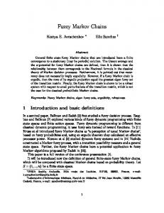
Introduction Motivation. The efficient synthesis of and motion planning for spatial closed chains, such as the spatial 4C mechanism shown in Fig. 1, requires the detection of self-collisions. Unfortunately, the current state of the art collision detection techniques are insufficient for these purposes. Hence, we propose a new modeling and analysis technique for definitive testing of self-collisions in spatial closed kinematic chains. The methodology presented here enables the user to model the links of the system using right circular cylinders and determine at the synthesis stage of the design, without defining detailed link geometry or building a virtual prototype, if any self-collisions occured in the desired motion. Cylinders have been used in previous works to model systems but not with the same modeling technique or mathematical approach presented here. In a related work, Merlet and Daney 关1兴 presents an efficient set of collision conditions, implemented using interval analysis, for a 6DOF Gough platform. In Corngold 关2兴 infinite cylinders are used to model a nuclear reactor particle’s possible collision with a containment field. Chang et al. 关3兴 used finite cylinders capped with hemispheres and spheres to model a simple system. Another case of using cylinders to model a system is found in the medical research field 关4兴 for protein chain packing. It models the chains using cylinders and tests the protein pairs for collisions. Cylinders are also frequently used in computer graphic renderings and in video games for quick collision detection. These systems are often simplified to two dimensional cases for quick calculations 关5兴. An advantage to using cylinders to model the geometry is that they can be represented as lines in space with an associated radius, and the distance between them can be definitively calculated. Zsombor–Murray 关6兴 presented the visualization of the shortest distance between two lines in space. His constructive geometry and algebraic solutions to the problem motivated the work presented here. Another unique aspect of the methodology presented Contributed by the Mechanisms and Robotics Committee of ASME for publication in the JOURNAL OF MECHANICAL DESIGN. Manuscript received December 22, 2006; final manuscript received June 5, 2008; published online August 18, 2008. Review conducted by Kwun-Lon Ting. Paper presented at the ASME 2005 Design Engineering Technical Conferences and Computers and Information in Engineering Conference 共DETC2005兲, Long Beach, CA, September 24–28, 2005.
Journal of Mechanical Design
here is the use of dual vector algebra to quickly and accurately perform the first level of testing. Other researches have used screws to describe just the motion 关7–9兴 of a system or to generate the model 关10兴 of the system, not test for collisions. This paper proceeds as follows. First, the distance calculations between infinite length cylinders, then finite length cylinders, are presented. The necessary kinematic analyses of the two degree of freedom spatial 4C mechanism are reviewed. Next, utilizing the distance calculations and the results of the spatial 4C analyses, we determine if a collision occurs for a spatial 4C mechanism. Finally, a case study for the self-collision detection of a spatial 4C mechanism is presented. Previous Works. In the state of the art for collision detection, there already exist a great number of techniques and software packages. They vary greatly in their modeling techniques, computational method, and thoroughness of testing. Here, we comment on the most pertinent packages, but a more thorough review may be found in Ketchel 关11兴. Currently, the most commonly used method for collision detection between cylinders is the Gilbert, Johnson, and Keerthi 共GJK兲 关12兴 algorithm, which uses an iterative method for computing the distance between the convex objects. The proximity query package 共PQP兲 关13兴 creates a hierarchy of rectangle swept spheres 共RSS兲, volumes covered by a sphere, whose center is swept over a 3D rectangle. It uses a specialized algorithm to improve the efficiency and robustness of the distance calculations. Distance calculations are performed between the RSSs on the hierarchal tree. These general methods are computationally intensive when compared to the algorithm presented here. SOLID 关13兴 computes the distance between any convex quadrics 共e.g., cylinders兲. It uses two algorithms for its collision detection methods. First, it creates a bounded hierarchal volume composed of axis-aligned bounding boxes 共AABBs兲. Second, it computes the distance between the two convex polytypes using the Minkowski difference and convex optimization techniques.
Collision Detection This section presents a complete description of the two levels of testing for self-collisions. The first uses dual vector algebra to test
Copyright © 2008 by ASME
SEPTEMBER 2008, Vol. 130 / 092305-1
Downloaded 18 Aug 2008 to 163.118.222.125. Redistribution subject to ASME license or copyright; see http://www.asme.org/terms/Terms_Use.cfm
S2 =
冉
冊
g−d g−d = 共wn,d ⫻ wn兲 ,d ⫻ 储g − d储 储g − d储
共2兲
We use the dual vector representation of the lines and dual vector algebra 关14,15兴 where ⑀2 = 0. Sˆ1 = 共sn,c ⫻ sn兲 = a + ⑀a0
共3兲
Sˆ2 = 共wn,d ⫻ wn兲 = b + ⑀b0
共4兲
In the line dot product, Sˆ1 · Sˆ2 = 共a,a0兲 · 共b,b0兲 = cos − ⑀d sin = cos ˆ
共5兲
In the line cross product, ˆ Sˆ1 ⫻ Sˆ2 = 共a,a0兲 ⫻ 共b,b0兲 = 共sin + ⑀d cos 兲Nˆ = sin ˆ N Fig. 1 A spatial 4C mechanism
for collisions between infinite length right circular cylinders. The second level definitively tests for all the possible interactions of two finite length right circular cylinders. Infinite Cylinder Testing. Initially, each object is modeled by a cylinder of infinite length and finite radius. Infinite cylinders are simple models to check for collisions since they can be represented as a line in space with a radius. The shortest distance between two lines in space is along their common normal line N. An advantage of using cylinders is that their common normal line has a finite line segment between the two cylinders, and by comparing the two cylinder’s radii to the length of that line segment, possible collisions can be detected. If the distance between the two cylinders is less than the sum of their two radii, then the infinite cylinders have collided. Hence, if the actual finite cylindrical objects have collided, it is necessary that the minimum distance between their associated infinite cylinders be less than the sum of their radii. The major axis of an infinite cylinder is a line. Here, we use normalized Plücker coordinates and dual vectors to represent these lines in space. Normalized Plücker coordinates define a line by its unit directional vector and moment. Moreover, when convenient, we employ dual vector algebra to operate on lines. The Plücker coordinates of a line can be generated from two points on the line or from a point and a direction vector 共see Fig. 2兲. For example, line S1 can be defined by points c and f or point c and unit direction vector sn 共see Eqs. 共1兲 and 共2兲兲 where the subscript n denotes that the vector has been normalized. S1 =
冉
冊
f−c f−c = 共sn,c ⫻ sn兲 ,c ⫻ 储f − c储 储f − c储
Fig. 2 Infinite cylinder notation
092305-2 / Vol. 130, SEPTEMBER 2008
共1兲
共6兲
The above expressions are useful for calculating the distance d and the angle between two lines. The resultant dual number of the dot product of two dual vectors yields the angle and the distance between the two lines as long as they are not parallel to each other 共see Eq. 共5兲兲. If d sin ⫽ 0, then the lines do not intersect 共d ⫽ 0兲 and are not parallel 共sin ⫽ 0兲. If d sin = 0 and cos ⫽ 1, then the lines intersect 共d = 0兲 and are not parallel. If the cos term of the dot product is equal to 1, then the lines are parallel and the resultant dual vector of the cross product will have its real component equal to 0. The cross product’s dual component 共d cos 兲 will equal 0 when the lines are identical. If d cos ⫽ 0, then the distance d can be calculated. This is an efficient method of determining the distance between the two infinite cylinders and if a possible collision has occurred. If the resulting distance is greater than the sum of the two radii, then no collision is possible regardless of the length of the finite cylinders. If the result is not greater than the sum of the two radii, then a collision may have occurred. If this necessary condition is satisfied, then additional testing is required. A finite cylinder model is used in the next stage of the collision detection algorithm to definitively determine if a collision has occurred. Finite Cylinder Testing. If a possible collision has been detected by the infinite cylinder test, then further testing is required to determine if a collision had occurred. The model is modified from cylinders of infinite length to cylinders of finite length. This changes the approach from testing lines to testing line segments. However, the same idea applies that the shortest distance between the cylinders is along their common normal, but the point where the common normal intersects the cylinder’s axis now becomes important. Figure 3 shows a detailed flow chart for finite cylinder testing. Parallel Testing. From the initial testing, the angle and the distance d between the infinite cylinders are known. The distance between the cylinders was found to be less than the sum of their radii. There are two general cases: Their associated line segments overlap in some manner 共collision兲 or there is no overlap 共no collision兲. To determine if they overlap, we project the start and end points of Cylinder 2 onto Cylinder 1’s axis 共see Fig. 4兲. The line parameter t values for the start and end projections of Cylinder 2 are calculated and ordered. The t values of Cylinder 1 are 0 and 1. By inspecting the order of the t values, any overlap can be found. If the t value order occur in pairs 共1-2,3-4 or 3-4,1-2兲, then no overlap or collision occurs 共see Fig. 4兲. Nonparallel Testing. We begin by determining where the common normal line intersects the axis of each cylinder. The axes S1 and S2 are described by their endpoints 共c and d兲 and nonunit direction vectors 共s and w兲, where 储s储 and 储w储 are equal to the length of their corresponding cylinder 共see Fig. 5兲. The common normal line N intersects the lines S1 and S2 at points p and q, respectively. Parametric equations for points p and q of lines S1 and S2 are 关15兴 Transactions of the ASME
Downloaded 18 Aug 2008 to 163.118.222.125. Redistribution subject to ASME license or copyright; see http://www.asme.org/terms/Terms_Use.cfm
Fig. 3 Flow chart: finite cylinder testing
p = c + t 1s q = d + t 2w
共7兲
where t1 =
关共d − c兲 ⫻ w兴 · n n·n
t2 =
关共d − c兲 ⫻ s兴 · n n·n n=s⫻w
Next, for each cylinder we determine the test point along its axis that is closest to the common normal line. These test points are referred to as TP1 and TP2. Then we determine if common normal points p and q are on the segments, before the segments, or after the segments. If t1 艋 0, then p lies at the start of the segment or earlier, so the start point of the cylinder is used as TP1. If t1 艌 1, then p lies at the end of the segment or further, and the Journal of Mechanical Design
end points of the cylinder are exchanged. This will result in t1 艋 0 so that the start point of the cylinder is used as TP1. If 0 ⬍ t1 ⬍ 1, then p lies on the line segment and p can be used as TP1. The above procedure is repeated for Cylinder 2 to determine TP2. From the determination of whether points p and q lie on or off the cylinders, there are three possible cases to consider 共see Fig. 6兲. If 0 艋 ti 艋 1, where i = 1 , 2, both p and q lie on the segments and On-On testing is necessary. If either but not both p and q lie on the segments, On testing is necessary. Additionally, if only one cylinder is on, the testing requires that it is Cylinder 1. If Cylinder 2 is on, all Cylinder 1 and 2 data are exchanged. If neither p nor q lie on the segments then Off testing is necessary. These cases are summarized below and discussed in detail in Refs. 关11兴 and 关21–23兴. Case 1: On-On Testing. If both points p and q lie on the finite cylinders, then a collision has occurred and no further testing is required. Case 2: On Testing. This case is addressed by finding the closest point along Cylinder 1’s axis to TP2 共see Fig. 7兲. This point p1 SEPTEMBER 2008, Vol. 130 / 092305-3
Downloaded 18 Aug 2008 to 163.118.222.125. Redistribution subject to ASME license or copyright; see http://www.asme.org/terms/Terms_Use.cfm
(a)
(b) Fig. 4 Finite cylinder test: parallel projection and overlap
is the intersection of lines S1 and N1 共N1 is orthogonal to S1 and passes through TP2兲. Calculating p1 共see Eqs. 共8兲兲 yields t3, which is used to determine if p1 lies on or off the cylinder. If the distance from TP2 to p1 is greater than the sum of the radii, then no collision is possible, and no further testing is required. Otherwise, the point TP⬘2, which is the closest point of Cylinder 2 to Cylinder 1’s axis, must be found. TP⬘2 is on the circular end of Cylinder 2 and
is found by determining the point on this circle nearest to Cylinder 2’s axis. The search returns t⬘3, TP⬘2, and p1, where p1 is the closest point along Cylinder 1’s axis to TP2⬘. Calculating p1 共see Eqs. 共10兲兲 yields t⬘3, which is used to determine if p1 lies on or off the cylinder. If 0 ⬍ t⬘3 ⬍ 1, then p1 lies in Cylinder 1, and if the distance between TP2 and p1 is less than the radius of Cylinder 1, a collision has occurred. If the distance is greater than the radius, no collision can occur and further testing is not required. If t3⬘ is outside the range, the test point of Cylinder 1 is off the end of the cylinder and End testing is required. 共8兲
p 1 = c + t 3s s · p1 = s · TP2 TP2⬘ = TP2 + r2关rot兴关cos
sin
关rot兴 = 关x y z兴
0兴T 共9兲
p1⬘ = c + t3⬘s s · p1⬘ = s · TP2⬘
Fig. 5 Finite cylinders notation
共10兲
Case 3: Off Testing. The distance from TP2 to S1 is found. If the distance is greater than the sum of the radii, then no collision is possible, since TP2 is the closest point on Cylinder 2 to Cylinder 1. If the distance is not greater than the sum of the radii, then on testing must be performed 共see Fig. 8兲. Additionally, the other end of Cylinder 2 must be similarly tested. End Testing. End cylinder testing is necessary when the circular ends of the cylinders may intersect 共see Fig. 9兲. It is possible for the test points, when the projections are added, to project on or off
Fig. 6 Cylinder testing
092305-4 / Vol. 130, SEPTEMBER 2008
Fig. 7 On testing notation
Transactions of the ASME
Downloaded 18 Aug 2008 to 163.118.222.125. Redistribution subject to ASME license or copyright; see http://www.asme.org/terms/Terms_Use.cfm
Table 1 Common normal and link parameters of the 4C mechanism Link
Dual angle
Twist
Length
␣ˆ ˆ ˆ ␥ˆ
␣  ␥
a h b g
Driving Coupler Driven Fixed
cussed in the Parallel Testing section is conducted. If the t4 and t5 ranges overlap then a collision has occurred. Fig. 8 Off testing: projecting on
The Spatial 4c Mechanism
the cylinder. When this occurs it is necessary to check if the cylinder ends intersect. The approach to test for collisions uses the distance from the line 共the intersection of the planes of the cylinder ends兲 to the test points. The first step is to find the equations of the planes 1 and 2 that are orthogonal to each cylinder’s axis and that pass through their test points. The parametric equation for the line of intersection N⬘ of 1 and 2 is then found. Next, the distance from TP1 to N⬘ is set to r1 to obtain a quadratic in t4:
冩冤 冥 x
r1 = 储N⬘ − TP1储 =
y + t4n − TP1 z
冩
0 = t24共n2x + n2y + nz2兲 + t4共2nx共x − TP1x兲 + 2ny共y − TP1y兲 + 2nz共z − TP1z兲兲 + 共共x − TP1x兲2 + 共y − TP1y兲2 + 共z − TP1z兲2 − r21兲 共11兲 Similarly, t5 can be found by setting the distance from TP2 to N⬘ equal to r2: 0 = t25共n2x + n2y + nz2兲 + t5共2nx共x − TP2x兲 + 2ny共y − TP2y兲 + 2nz共z − TP2z兲兲 + 共共x − TP2x兲 + 共y − TP2y兲 + 共z − TP2z兲 − 2
2
2
r22兲
共12兲
if the quadratic yields complex roots, then the cylinder end circle and the line N⬘ do not intersect, and no collision is possible. Repeated roots mean that the cylinder end circle is tangent to the line N⬘, and no collision has occurred. If both roots are real then a range is found for t4 and t5. Overlap testing similar to that dis-
A spatial 4C robotic mechanism has four cylindrical joints, each joint permitting relative rotation and translation along a line 共see Fig. 1兲. The frame’s axes are color coded red, green, and blue to correspond with the local XYZ axes. The link parameters that define the mechanism are listed in Table 1, and the joint variables are defined in Table 2. The spatial 4C mechanism may be viewed as a combination of two CC dyads. The driving CC dyad has four independent joint variables, referred to as , d1, , and c1. The driven dyad also has four independent joint variables, , d2, ␦, and c2. When adjoined by the coupler link, the two dyads form a closed chain spatial 4C mechanism with two degrees of freedom. We chose and d1 to be the independent joint variables. A complete kinematic analysis of the spatial 4C mechanism may be found in Refs. 关16,17兴. The next sections contain a description of the mechanism and the methodology for collision testing. They present the generation of the infinite and finite cylinder data, calculation of the mechanism’s maximum translational values, and the cylinder testing logic that reduces the number of tests that must be performed.
Mechanism Collision Testing Our implementation of the self-collision detection algorithm presented here utilizes a set of via points that describe the desired motion, the constant link parameters of the spatial 4C mechanism 共␣, , ␥, , a, b, g, and h兲, the radii of each link and collar, and the height of each collar. Part 1: Analyzing Mechanism Mechanism Angles. The link parameter twist angles are tested to verify that the mechanism can be assembled. If any twist is larger than the sum of the other three, then the mechanism cannot be assembled. Also the T values that are used to classify the mechanism’s spherical image can also be inspected 关18兴: T1 = ␥ − ␣ + −  T2 = ␥ − ␣ − +  T3 = +  − ␥ − ␣ T4 = 360 − −  − ␥ − ␣ Table 2 Moving axes and joint variables of the 4C mechanism Joint axis Fixed Driving Coupler Driven
Fig. 9 End testing: cylinder end overlap
Journal of Mechanical Design
Dual angle
Rotation
Translation
ˆ ˆ ␦ˆ ˆ
␦
d1 c1 c2 d2
SEPTEMBER 2008, Vol. 130 / 092305-5
Downloaded 18 Aug 2008 to 163.118.222.125. Redistribution subject to ASME license or copyright; see http://www.asme.org/terms/Terms_Use.cfm
Table 3 Segment designations of the spatial 4C mechanism Segment No. 1 2 3 4 5 6 7 8 9 10 11 12
Fig. 10 4C mechanism point designation
If any of these are zero then the mechanism is a special type Grashof and the mechanism folds 关18兴. Folding inherently results in at least one self-collision. Via Points. The set of via points contains the input values for , d1, the number of incremental steps to the next via point, and which solution to use for . From this given information, several tests can be performed to see if the mechanism is unsatisfactory. Each via point’s value can be tested to make sure that it is within the allowable motion range of the mechanism. The allowable motion range can be calculated using the link twist angles of the mechanism 关18兴. If any of the via point’s values are not in the allowable range, the motion is not acceptable. In addition, each via point’s d1 can be checked for a sign change or if it is less than the sum of the link’s radii plus half the collar height. In spatial 4C mechanism design, often the common normal is used to define the portion of the link that connects the collar to its axis, as done in the 4C mechanism design software packages SPADES 关17兴 and VRSPATIAL 关19兴. If the sign of d1 changes or if it is less than the sum, a collision will occur between the driving link’s collar and the fixed link’s common normal 关20兴. This same analysis can be performed for each of the mechanism’s translational values 共d2, c1, and c2兲. Similarly, the solution set can be inspected. has two solution sets and the remaining calculations are based on only one of the sets for the mechanism to be acceptable. If the set changes, the mechanism changes circuits and/or moves through a singular configuration 关20兴. Part 2: Infinite Cylinder Generation. The next step in testing the mechanism for a possible collision is generating the Plücker coordinates of its axes and collars at each incremental step with respect to the fixed frame F. We assign right-handed frames to the mechanism that translate and rotate along and about the local X and Z axes only 共see Fig. 1兲. Part 3: Determining Moving Axis Lengths. The links of a spatial 4C robotic mechanism can be modeled by 12 line segments. The four axes and four common normals form a closed chain of eight segments defined by 12 points 共see Fig. 10兲. Each of the four links is described by three points: one at the center of the link’s collar, the elbow defined by the intersection of the link’s common normal with its axis, and the end defined as the opposite end of its axis. The collars of the mechanism are the final four line segments of the mechanism. Although each link’s collar is colinear with the previous link’s axis, separate points are required for it and for the end of the moving axis. We assume that each link axis is rigid and that its length will be sized to accommodate the translations that it must support. Hence, it is necessary to find the maximum length of each link’s axis for 092305-6 / Vol. 130, SEPTEMBER 2008
Start point
Endpoint
Fixed elbow Fixed end Driving collar Driving elbow Driving elbow Driving end Coupler collar Coupler elbow Coupler elbow Coupler end Driven collar Driven elbow Driven elbow Driven end Fixed collar Fixed elbow Driving collar Coupler collar Driven collar Fixed collar
the desired motion. We use linear interpolation of the and d1 via points to yield a discretized representation of the desired motion. At each discrete step of the motion, we perform a kinematic analysis of the mechanism and the minimum and maximum values of c1, d2, and c2 are determined. The minimum lengths are checked for possible collisions by making sure that they are greater than the sum of the link’s radii and half the collar height. The maximum lengths are used to define the lengths of the finite cylinders that are used to model the link axes for collision detection via finite cylinder testing. Part 4: Finite Cylinder Generation. The next step in testing the mechanism is generating the segment endpoints for each of the possible collision segments saved and identified during the infinite length cylinder testing. For each linear interpolation of and d1, the endpoints of any segment can be generated by using the above kinematic analyses. For each incremental step, the 12 points are calculated and the 12 line segments generated. The closed chain’s segments, skipping the collars, are numbered 1–8 starting with the fixed link’s axis, proceeding around the closed chain, and ending with the fixed link’s common normal 共see Table 3兲. Following along the same path, the collars are then numbered 9–12. This yields the set of finite line segments for each incremental step that is then tested to see if a collision has occurred.
Cylinder Testing Logic At each incremental step every cylinder is tested for possible collisions. First, the infinite cylinder test is used, and if necessary the finite cylinder test is then performed. Since the speed of calculation is important, we look to reduce the number of tests that must be run for each incremental step. First, cylinders cannot collide with themselves since they are rigid links. Moreover, testing Cylinder 1 for a collision with Cylinder 5 is redundant to checking Cylinder 5 to Cylinder 1. This greatly reduces the number of tests required. The number can be further reduced by observing the geometric structure of the mechanism. In a spatial 4C robotic mechanism, it is not possible for a cylinder to collide with its adjacent cylinders. This eliminates, for example, testing between Segments 1 and 2 and Segments 2 and 3. Additionally, the calculated translational minimum/maxima can be used to eliminate tests during the initial testing phase between the collars and the axes that are too far away from each other. For example, Segment 2 cannot collide with Segment 4 without first colliding with collar Segment 10. Segment 2 collides with Segment 10 if the distance c1 is less than the sum of the link’s radii plus half the collar height. Segment 2 collides with Segment 4 if the distance c1 is less than the sum of both of the links’ radii. This reduces the number of possible cylinder combinations in a spatial 4C robotic mechanism to 26, see Table 4. Furthermore, during the infinite cylinder testing phase of the analysis pair tests can be sped up and/or eliminated. The axis of Transactions of the ASME
Downloaded 18 Aug 2008 to 163.118.222.125. Redistribution subject to ASME license or copyright; see http://www.asme.org/terms/Terms_Use.cfm
Table 4 Segment collision testing pairs Test Segment No.
Segment Nos.
1 2 3 4 5 6 7 8 9 10
4, 5, 6, 11 5, 6, 7, 11, 12 6, 7, 8, 12 7, 8, 9, 12 8, 9 9, 10 10 10, 11 11 12
the collar located at the origin of Frame 2 is identical to the moving axis of the fixed link. This allows for the same Plücker coordinates to be used for the distance calculation between infinite cylinders involving the collar or the moving axis. For example, Segments 1 and 9 have the same Plücker coordinates. Note that for infinite cylinder generation, the axis of the collar located at the origin of Frame 2 is identical to the moving axis of the fixed link. The same is true for Segments 3 and 10, 5 and 11, and 7 and 12.
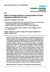
Case Studies Two Hit Case. To demonstrate the methodology presented, we use the spatial 4C mechanism described in Table 5. The mechanism’s fixed link is gray, the driving link green, the driven link red and the coupler link blue 共see Figs. 11 and 12兲. Each link’s common normal and moving axis were assigned a radius of 5 units. Each axis’s collar is given a radius of 20 and a total height, centered at the collar point, of 40 units. A set of via points 共see Table 6兲 was then entered for the mechanism, and some initial testing was performed. The allowable range of was calculated, and it was determined that the input link is capable of full rotation. After calculating the allowable range, each of the via points was tested to make sure that
Fig. 12 4C Case study 2: one hit collision
they were within the same allowable range. The next step is to begin incrementally moving the mechanism through its desired motion. At each step, the first level of collision testing is performed using infinite length cylinders. If a possible collision is detected, the data that describe the mechanism’s position and the segments that may have collided are written to a file. For complete testing, not examining the translations, 6936 infinite cases must be tested of which 939 resulted in possible collisions 共see Table 7兲 that required further testing. If the test for the collision between the collar and the fixed axis is tested at this level, there would always be a collision since their axes intersect, by definition, at a right angle. By examining the translational values to determine if a collision occurs between collars and fixed axes, infinite testing can be quickened. This removes eight tests at each incremental step, four at least of which automatically result in infinite cylinder collisions. Table 8 shows the difference in the number of infinite 共5304兲 and finite 共321兲 tests required if the translations are used instead of performing cylinder testing calculations. Of course both tests identify the same collisions. Also,
Table 5 4C Case studies: link parameters Dual angle
Twist 共deg兲
Length 共unit兲
␣ˆ ˆ ␥ˆ ˆ
␣ = 10  = 45 ␥ = 65 = 55
a = 100 b = 70 g = 90 h = 80
Table 6 4C case study 1: motion input
共deg兲
d1 共unit兲
Increments
⫾
30 10 −10 10 −20
90 120 80 90 80
50 40 60 50 NA
⫹ ⫹ ⫹ ⫹ ⫹
Table 7 4C Case study 1: complete infinite cylinder testing Seg. No.
Seg. No.
Infinite tests
Infinite collisions
Finite collisions
2 2 2 3 3 4 4 6 6 8
4 8 10 7 12 6 11 8 12 9
204 204 204 204 204 204 204 204 204 204
6 0 204 117 204 0 204 0 204 204
6 0 52 9 124 0 0 0 0 0
Other 24 pairs Total
4896 6936
0 939
0 191
Fig. 11 4C Case study 1: two hit collision
Journal of Mechanical Design
SEPTEMBER 2008, Vol. 130 / 092305-7
Downloaded 18 Aug 2008 to 163.118.222.125. Redistribution subject to ASME license or copyright; see http://www.asme.org/terms/Terms_Use.cfm
Table 8 4C Case study 1: partial infinite cylinder testing „using translations… Seg. No.
Seg. No.
Infinite tests
Infinite collisions
Finite collisions
2 2 2 3 3 4 4 6 6 8
4 8 10 7 12 6 11 8 12 9
0 0 0 204 204 0 0 0 0 0
0 0 0 117 204 0 0 0 0 0
6 0 52 9 124 0 0 0 0 0
Other 24 pairs Total
4896 5304
0 321
0 191
Collision Type
Seg. No.
Seg. No.
共deg兲
d1 共unit兲
One hit Two hit Two hit
3 2 2
7 4 10
−20.0 −20.0 −20.0
80.0 80.0 80.0
Conclusions
during the incremental movement, the global translational minima and maxima of the mechanism are determined 共see Table 9兲. Inspection of the mechanism’s translations shows that there were no sign changes in any joint translations and that none of them approached zero. Next the second level of testing using finite length cylinders is performed on each of the identified possible collisions. There were 191 collisions detected. The collisions occurred between Segments 3 and 7, Segments 3 and 12, Segments 2 and 4, and Segments 2 and 10. Figure 11 shows the mechanism when it is in one of the collision configurations, where = −20.0 and d1 = 80.0 共see Table 10兲 and four cylinder pairs collide. The collision between Segments 3 and 7, Segments 2 and 4, and Segments 2 and 10 are a two hit collision case where both test points of the finite cylinders lie within the cylinders. The collision between Segments 3 and 12 is an end hit where the ends of the two finite cylinders collide. One Hit Case. We now study the same mechanism when the desired motion has been slightly altered by changing the second via point’s value of d1 from 120 to 100. This changes the translational outputs of d1 max to 100 and c1 max min to −64.8940. These new translational values shorten two of the link segments so that the number of infinite collisions is still the same but the number of finite collisions is now 118. Segments 2 and 4, Segments 2 and 10, and Segments 3 and 7 still collide 共see Fig. 12兲, but Segments 3 and 7 collision is now a one hit case 共see Table 11兲. Also, with the new via points, Segment 3 is now shorter and no longer collides with Segment 12 for these input values.
Table 9 4C Case study 1: translation output Translation
Min 共unit兲
Max 共unit兲
d1 c1 d2 c2
80.000 −80.1164 −153.9905 79.3920
120.000 −5.6260 −70.7963 113.3022
Table 10 4C Case study 1: results Collision type
Seg. No.
Seg. No.
共deg兲
d1 共unit兲
Two hit End hit Two hit Two hit
3 3 2 2
7 12 4 10
−20.0 −20.0 −20.0 −20.0
80.0 80.0 80.0 80.0
092305-8 / Vol. 130, SEPTEMBER 2008
Table 11 4C Case study 2: results
A methodology for detecting self-collisions in spatial closed kinematic chains has been proposed. It was shown that this selfcollision detection methodology is applicable to motion planning of spatial closed chains. This algorithm uses line geometry and dual number algebra to exploit the geometry of right circular cylindrical objects. First, the rigid bodies are modeled with infinite cylinders, and an efficient necessary condition for collision is evaluated. If the necessary condition is not satisfied, the two bodies do not collide. If the necessary condition is satisfied, a collision between the bodies may occur, and we proceed to the next stage of the algorithm. In the second stage, the bodies are modeled with finite cylinders and a definitive necessary and sufficient collision detection algorithm is employed. The result is a straightforward and efficient means of detecting self-collisions of cylindrically shaped bodies moving in three dimensions. This methodology has applications in spatial mechanism design, especially in the kinematic synthesis and motion planning stages of design. A case study examining a spatial 4C mechanism for selfcollisions was included.
Acknowledgment This material is based on the work supported by the National Science Foundation under Grant No. 0422705.
References 关1兴 Merlet, J. P., and Daney, D., 2006, “Legs Interference Checking of Parallel Robots over a Given Workspace or Trajectory,” Proceedings of the 2006 IEEE International Conference on Robotics and Automation, IEEE, New York. 关2兴 Corngold, N., 2002, “Kinetic on the Collision Probability for the Infinite Cylinder,” Ann. Nucl. Energy, 29 pp. 1151–1155. 关3兴 Chang, C., Chung, M., and Bien, Z., 1990, “Collision-Free Motion Planning for Two Articulated Robot Arms Using Minimum Distance Functions,” Robotica, 8, pp. 137–144. 关4兴 Lee, S., and Chirikjian, G., 2004, “Helix-Helix Packing in Protiens: The Kinematics of Interacting Line Segments,” International Symposium on Advances in Robot Kinematics, Sestri Levante, Italy, pp. 199–210. 关5兴 2005, http://spiritking.tripod.com/cdtut.htm. 关6兴 Zsombor-Murray, P. J., 1992, “Spatial Visualization and the Shortest Distance Between Two Lines Problem,” Proceedings of the 5th ASEE International Conference ECGDG, Melbourne, Australia. 关7兴 Byungmoon, K., and Rossignac, J., 2003, “Collision Prediction,” ASME J. Comput. Inf. Sci. Eng., 3, pp. 295–301. 关8兴 Kim, B., and Rossignac, J., 2003, “Collision Prediction for Polyhedra Under Screw Motion,” Proceedings of the Eighth ACM Symposium on Solid Modeling and Applications, pp. 4–10. 关9兴 Pennock, G., and Meehan, P., 2001, “Geometric Insight Into the Dynamics of a Rigid Body Using The Spatial Triangle of Screws,” Proceedings of the ASME 2001 Design Engineering Technical Conferences and Computers and Information Conference, Paper No. DET2001/DAC-21114. 关10兴 Xavier, P., 2000, “Implict Convex-Hull Distance of Finite-Screw-Swept Volumes,” Proceedings of the 2002 IEEE International Conference on Robotics and Automation. 关11兴 Ketchel, J., 2006, “Collision Detection of Cylindrical Rigid Bodies Using Line Geometry,” Ph.D. Dissertation, Florida Institute of Technology, Melbourne, Florida. 关12兴 Gilbert, E. G., and Foo, C. P., 1990, “Computing the Distance Between General Convex Objcts in Three-Dimensional Space,” Proceedings of the 1990 IEEE International Conference on Robotics and Automation, IEEE, New York. 关13兴 Caselli, S., Reggiani, M., and Mazzoli, M., 2002, “An Experimental Evaluation of Collision Detection Packages for Robot Motion Planning,” IEEE International Conference on Intelligent Robots and Systems, Lausanna, Switzerland. 关14兴 Fischer, I., 1999, Dual-Number Methods In Kinematics, Statics and Dynamics, CRC LLC, Boca Raton, FL. 关15兴 McCarthy, J. M., 2000, Geometric Design Of Linkages, Springer-Verlag, New York.
Transactions of the ASME
Downloaded 18 Aug 2008 to 163.118.222.125. Redistribution subject to ASME license or copyright; see http://www.asme.org/terms/Terms_Use.cfm
关16兴 Duffy, J., 1980, Analysis of Mechanisms and Robot Manipulators, Wiley, New York. 关17兴 Larochelle, P., 1998, “Spades: Software for Synthesizing Spatial 4C Mechanisms,” Proceedings of the ASME 1998 Design Engineering Technical Conferences and Computers and Information Conference. 关18兴 Murray, A. P., and Larochelle, P., 1998, “A Classification Scheme for Planar 4R, Spherical 4R, and Spatial RCCC Linkages to Facilitate Computer Animation,” Proceedings of the ASME 1998 Design Engineering Technical Conferences and Computers and Information Conference, Paper No. DET1998/ MECH-5887. 关19兴 Kihonge, J., Vance, J., and Larochelle, P., 2002, “Spatial Mechanism Design in Virtual Reality With Networking,” ASME J. Mech. Des., 124共1兲, pp. 435– 440. 关20兴 Larochelle, P., 2000, “Circuit and Branch Rectification of the Spatial 4C
Journal of Mechanical Design
Mechanism,” Proceedings of the ASME 2000 Design Engineering Technical Conferences and Computers and Information Conference, Paper No. DET2000/MECH-14053. 关21兴 Ketchel, J., and Larochelle, P., 2004, “Line Based Collision Detection of Cylindrical Rigid Bodies,” Proceedings of the 2004 ASME International Design Engineering Technical Conferences, ASME, New York, Paper No. MECH57473. 关22兴 Ketchel, J., and Larochelle, P., 2005, “Collision Detection of Cylindrical Rigid Bodies Using Line Geometry,” Proceedings of the ASME 2005 Design Engineering Technical Conferences and Computers and Information Conference, Paper No. DETC05/MECH-84699. 关23兴 Ketchel, J., and Larochelle, P., 2006, “Collision Detection of Cylindrical Rigid Bodies for Motion Planning,” Proceedings of the 2006 IEEE International Conference on Robotics and Automation, IEEE, New York.
SEPTEMBER 2008, Vol. 130 / 092305-9
Downloaded 18 Aug 2008 to 163.118.222.125. Redistribution subject to ASME license or copyright; see http://www.asme.org/terms/Terms_Use.cfm