Self-Reconfigurable Modular Robots – Hardware and Software Development in AIST – Eiichi Yoshida* , Satoshi Murata** , Akiya Kamimura* , Kohji Tomita* , Haruhisa Kurokawa* and Shigeru Kokaji* * Intelligent Systems Institute, National Institute of Advanced Industrial Science and Technology (AIST) Tsukuba East, 1-2-1 Namiki, Tsukuba-shi, Ibaraki 305-8564 Japan
[email protected] ** Department of Computational Intelligence and Systems Science, Interdisciplinary Graduate School of Science and Engineering, Tokyo Institute of Technology, 4259 Nagatsuta-cho, Midori-ku, Yokohama, Kanagawa 226-8502 Japan Abstract In this paper we present the development of hardware and software of self-reconfigurable modular robots in National Institute of Advanced Industrial Science and Technology (AIST), Japan. Thanks to their flexibility, versatility and fault-tolerance, self-reconfigurable modular robots are expected to be used in various application fields, such as space, rescue or micro-sized world. Our research group has been pioneering this new field and developed several hardware prototypes and corresponding software that exploit the robots’ potential. We have been successfully demonstrated the feasibility of the self-reconfigurable modular robots based on experiments from different aspects. Starting from two-dimensional (2D) self-assembling and self-repairing machine Fractum, we review hardware development in diverse directions, like to micro-world, threedimensional (3D) structures and motions; as well as the progress of control software, including distributed control and recent evolutionary motion acquisition.
1
Introduction
Self-reconfigurable modular robots are composed of many modules and are capable of changing their configuration. Those robots, therefore, have adaptability, flexibility and versatility since they can reconfigure themselves to be different types of robots, according to their surrounding environment without external help. By applying decentralized control to those robots, they can have fault-tolerance to recover from partial damage. These advantages have been attracting more and more researchers’ interest and many studies have been conducted so far in two dimensions (2D) [1]–[10] and three dimensions (3D) [11]–[26]. Self-reconfigurable modular robots are useful in situations where they should move and work in hazardous, unstructured or unknown environments, as well as in case where they are required to achieve different tasks, but not specified beforehand. The potential applications of self-
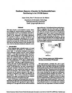
reconfigurable modular robots range from static structure to mobile robots. They can be applied to satellite antennas, space stations, or deep-sea structures, for example, to keep their strength according to applied force from outside. As mobile robots, the self-reconfigurable modular robots can be planetary exploring vehicle, rescue robots to search for survivors. They can also be applied to robots working around micro-sized world. An example is a microrobot that moves around inside pipes in chemical plants by changing its shape and reorganizing itself as a manipulator to execute repairing tasks when it detects a fault. Our group in AIST has been one of the frontier pioneers in this field over past ten years. In this paper, we review our achievement of developments starting from the first model of self-assembling machine, as well as recent development of self-reconfigurable modular robots. Figure 1 shows how the development has proceeded in different research directions including micro-sizing, versatile structure and dynamic motions; we have been exploring various possibility of application for self-reconfigurable modular robots. Tracing those developments, we will try to clarify the important research issues to be solved in the future.
M-TRAN (‘99-)
Dynamic Motion
Micro module (‘98-)
3D rld o W
3D Self-reconfig. Structure (‘97-)
ro Mic ld r o w
Micro-sizing
2D Fractum (‘93-) Versatile Structure
Fig. 1: Development of self-reconfigurable robots in AIST.
modular
2
Fractum – Self-assembly and Self-repair
Fractum [2], we believe, is the first modular robot that demonstrated the self-assembly and self-repair through hardware experiments. The development of Fractum raised a major conceptual shift of robot since it showed selfassembly and self-repair capacity based on modular structure and distributed control scheme.
2.1 Hardware A Fractum module has a hardware shown in Fig. 2. The module is mainly composed of actuation part using electroand permanent magnets and information processing part using a microcomputer. The actuation part of a module has three-layered structure, with three pairs of permanent magnets in the top and the bottom layer and three electro-magnets in the middle. By changing the polarity of an electro-magnet, it is attracted into, or repulsed from the gap between outer layers of another module. Two modules change their connection by an appropriate sequence of electro-magnet operations as shown in Fig. 3. A module can connect with maximum six modules. Although the design of one module is simple, a collection of those identical modules can configure a variety of shapes by changing their connections. The module is also equipped with serial optical channels for local bilateral communication.
2.2 Distributed Self-Assembly/Repair Software We have developed distributed self-assembly and selfrepair algorithms [5, 6], which are featured by the homogeneity as well as the hardware. Each module can decide
information processing part (CPU, control unit) optical communication channel
their behavior based only on local communication using the same software downloaded to each module’s microprocessor. The algorithm was developed to achieve a target configuration, described as a collection of local connection, from given initial states. Communication synchronization is also implemented in a distributed manner [27]. The basic procedure of the algorithm is as follows [5]. (i) Each module calculates such measures as • “difference” between the current and the target configuration. • “irritation” which increases during deadlock. (ii) estimates the average difference around the module using a diffusion process through the inter-module communication. (iii) if the module has relatively large difference, it moves towards the direction to make it smaller. Figure 4 shows the self-assembly and self-repair experiment using eleven modules. Here the target configuration is a ten-module triangle with one spare module, completed in Fig. 4c. When one of the modules is given simulated fault by cutting its power source in Fig. 4d, the self-repair process starts to restore the original triangular configuration as shown in Fig. 4e. This was the first hardware experiment that demonstrates the self-repair capacity using more than ten modules.
3 Micro-sizing: Using SMA Actuator In pursuit of applications in micro-world, we have investigated micro-sized module using shape memory alloy
starting self-assembly
(a)
cutting off the defective unit
electro-magnet
(d)
permanent magnet
ball caster
(b) Fig. 2: Structure of a module “Fractum.”
spare unit
push
A
B
A
B
A
B
self-repair completed
pull [ transient ]
Fig. 3: Basic module motion by two modules A and B. Module B rotates itself by 60◦ through proper magnet operations.
(e)
defective unit (power cut)
(c) Fig. 4: Self-assembly and self-repair experiment.
(SMA) actuators [8]–[10]. This module has a square shape where two actuators at orthogonal vertices rotate male connecting parts, which can be connected to female parts in another module. The basic motion of the modules is illustrated in in Figs. 5 (a)–(c). The SMA actuator is suitable especially in micro-size thanks to its constant high power/weight ratio and faster response at smaller scales. We have devised an actuator mechanism using SMA torsion coil springs shown in Fig. 6 to guarantee both large torque and wide motion range. We developed the first micro-sized model that measures 5cm cube and weighs 80g (Fig. 7) and the second model with 2cm cube size and 15g weight (Fig. 8). We have demonstrated their self-reconfiguration capacity by manymodule experiments (Figs. 9(a)–(c), with the first model). This module can also be extended in three-dimensions [10].
U2
(1)
B
U2
(3)
B U2 (c)
(b)
(a)
U1
(2)
A
U1
Rotational actuators
(a) A
B
U1
Initial state
Target shape
Connecting part Connecting part (female) (male)
A
Fig. 8: Micro-sized module (2nd Model).
Fig. 5: Basic motion of two micro-sized modules. < not heated >
connecting part (male)
< heated > restoring memorized 0 shape
SMA torsion coil springs
fixed points
(b)
(c)
Fig. 9: Reconfiguration experiment using 6 modules.
4 3D Self-reconfigurable Modular Structure < not heated >
[original center position] (twisted 180 for pre-loading)
memorized shape
< not heated >
[rotating CW] (heating upper spring)
Fig. 6: Rotation actuator using SMA torsion coil springs.
Control unit
SMA torsion coil springs
Besides micro-sizing, the development has been directed into 3D versatile structure. This extension greatly widens the applications of self-reconfiguration modular robots, especially in many dangerous environments that human cannot access. It can be used as a prime structure for a space station such as the beam for a solar panel. Not only can it repair itself without human help, it can be reused as a structure with another shape and function. Development of 3D homogeneous module is a difficult design problem since uniform connection capacity in 3D must be realized. Our first 3D modular structure presented in this section has strict spatial isotropic property; one module has a symmetrical structure for the connection in all orthogonal directions.
4.1 3D Module Hardware Rotating drum (holes)
Connecting pins (auto-locking)
Fig. 7: Overview of a micro-sized module using SMA actuator (1st Model).
We have devised a 3D self-reconfigurable modular structure that has six rotation arms with connecting hand in three orthogonal axes as shown in Fig. 10. The hardware of this 3D module utilizes one DC motor
as an actuator. The module has a central box containing a motor with a power transmission system (Fig. 11) that distributes torque to one of 12 axes of arm rotation mechanisms or connection hands. The connection hand has a special mechanism so that the same hand can connect to each other rigidly. The high reduction ratio and rigid connection enables a module to lift another against gravity. A jungle-gym like structure can be constructed using those modules, and the structure can change its configuration by repeating basic pairwise motion (Fig. 12). Two connected modules X and Y are on a plane made of the same modules in the initial configuration in Fig. 12a. Module X becomes the “carrier” for module Y to move to the final position shown in Fig. 12b. To realize this, module Y releases its connection to the plane and is then carried as X rotates by the vertical axis, finally connects to the underlying module in the plane.
4.2 3D Distributed Reconfiguration Method A homogeneous self-repair method for a 3D modular robot must be developed since methods for a 2D system cannot be straightforwardly extended to 3D because of far more degrees of freedom. To cope with such combinatorial complexity of a 3D system, we have developed a new distributed method based on a recursive configuration description and local message passing. The target configuration is expressed as a recursive graph
Connecting hand
which determines the geometrical relationship between “nodes.” In the lowest level, the node denotes a module, but in the upper second level, it represents a group of nodes in the lowest level. In the third level, a node is equivalent to a group of nodes in the second levels, and so on. Self-assembly starts from the top layer of the description and the modules generate necessary messages to transmit to neighbors. In this method, the goal structure is roughly shaped in the early stage, then the detailed structure is constructed in a distributed and concurrent manner as the selfassembly proceeds. Figure 13 shows a simulation result of self-assembly and self-repair of a 56-module structure, starting from a 60-module box shape.
5 Recent Development: M-TRAN for 3D Structure and Dynamic Motion Hardware of 3D reconfigurable modular robotic system is classified into two types, lattice type [11]–[17] including 3D self-reconfigurable modular structure introduced in the previous section, and linear type [19]–[21]. The former corresponds to a system where each module has a fixed geometry of connections, and a group of them can construct various types of static lattice structure such as a junglegym. By contrast, it is difficult for such a system to generate some dynamic robotic motions. On the other hand, the snake-like shape of the latter can generate dynamic motions, nevertheless self-reconfiguration is difficult for them. We have recently developed a new type of modular robot
Rotating arm
Fig. 10 A 3D module.
Fig. 11:
b
b
X
X
3D hardware.
Z
Gray units reached posi- Self-assembly completed tions in goal shape Self-assembly of 56-unit structure
Y spare units
Y
b
Initial state
b
Z
(a) (b) Fig. 12: Typical pairwise motion of three-dimensional module. (a) Initial configuration. (b) Final configuration after pairwise motion of modules X and Y (X rotated about axis b-b).
4 units lost
Starting self-repair
Self-repair after breakdown of units
Self-repair completed
Self-repair after breakdown of units
Fig. 13: Self-assembly and self-repair simulation of 3D modular structure.
that has both lattice type and linear type features, called MTRAN (Modular TRANsformer) [22]–[26]. The module has a simple bipartite structure. Each part rotates about an parallel axis by geared motors and has three magnetic connecting faces (Fig. 14). M-TRAN can form various shapes, such as a legged walking robot or snake robot. Software has also been developed to deal with problems of reconfiguration planning and motion generation, whose complexity comes from M-TRAN’s non-isotropic geometric property. This section outlines those recent issues on hardware and software development of M-TRAN.
5.1 M-TRAN Module Hardware Figure 15 shows the newest model “M-TRAN II.” Each module has two semi-cylindrical parts, active and passive parts, and two geared motors inside the link. The active part has a movable plate with magnets that rises to the surface by the attractive force of the magnets embedded in the passive part of another module, to connect electrically and mechanically. Two surfaces can be detached automatically by heating the shape memory alloy coils by small light bulbs. Figure 16 illustrates the internal structure of a module. Electrodes are placed symmetrically on the same surface Face 0 Face 1
Face 2 Unit length
Part 1
xm ym
θ1
pm zm
θ0
Part 0
Fig. 14: A module of M-TRAN. Passive
GND
Active
VCC (8V)
Global Communication (RS-485) Permanent magnet (S) Local communication
Non-linear spring
Main-CPU PIC-P Neuron chip
Acceleration sensor
The motion generation software of M-TRAN has two aspects, reconfiguration planning and locomotion pattern generation. The former plans how the modular robot reconfigure itself, and the latter provides appropriate motion patterns for given configuration. In this section we address those software developments. A. Reconfiguration planning using local rules Despite the greatly improved versatility of M-TRAN through simplified module design, its motion planning is not straightforward because of module’s restricted degrees of freedom and non-isotropic spatial property of movability. Since distributed planning cannot directly applies, we have developed two-layered centralized framework, composed of global and local planner (Fig. 17) for reconfiguration of a class of regular structures [24]. This reconfiguration is based on locomotion by multi-module blocks. The global planner decides the overall motion called “flow” for the cluster to trace the given 3D trajectory by sending the “tail” modules towards the “head.” The local planner decomposes the global motion into individual motions based on a database of local rules. Each rule includes a local reconfiguration motion called “motion scheme” that is associated with an applicable local configuration. From among matched rules, the local planner selects a rule that gives the maximum distance to realize the global motion. This method is classified as a centralized method. Figure 18 shows some snapshots taken from the planned motion of a cluster of 22 modules starting from a configura-
Module cluster
Geared motor
Desired trajectory
Light bulb
PIC-A
Power supply circuit
5.2 Planning and Motion Pattern Generation
Locomotion Using Reconfiguration
Link
Fig. 15: A hardware module of M-TRAN II. Li-ion battery
for the power supply, global communication, and local communication. A CPU circuit board is equipped inside the passive part, including a microprocessor for global and local inter-module communication. A power supply circuit board and a battery are also embedded. Power for the module can be supplied by an internal battery or by connecting wires from outside to one of the modules.
Conneting plate Permanent magnet (N) SMA coil
Fig. 16: Internal structure of a M-TRAN II module.
Input:
Locomotion Planner Global planner Local Planner Planning overall Decomposing into cluster flow individual motions
Planning output: Locomotion plan
Add and update:
Rule database
Fig. 17: Reconfiguration planner architecture.
Desired flow direction 90 vertical
z 90 horizontal
x
y
Current direction
Fig. 18: Simulated plan of motions in different flow directions from initial configuration on a plane. tion on a plane. The cluster first changes its flow direction in the horizontal plane, then moves in a vertical direction. This simulation result demonstrates that this approach effectively solves the complicated planning problem. B. Evolutionary generation of locomotion pattern For robots with full-body dynamic motion capacity like M-TRAN, this motion synthesis is as important as the reconfiguration planning to fully exploit the high mobility of modular robot. However, due to many degrees of freedom of modular robot, motion synthesis of modular robots also becomes a computationally difficult problem. We have developed a couple of evolutionary pattern generation methods for this purpose using genetic algorithms (GA). In the first method called ERSS (Evolutionary Reconfiguration Sequence Synthesis) [25], the GA is applied to the motion sequence directly. This method is characterized by its simplicity and ease of extension to evolutionary synthesis of plans including configuration changes. The second method is called ALPG (Automatic Locomotion Pattern Generation) Method [26] which seeks locomotion pattern for an arbitrary module configuration using a neural oscillator as a CPG (Central Pattern Generator) model and GA to optimize the parameters for locomotion. B-1. Evolutionary Reconfiguration Sequence Synthesis The ERSS method is characterized by its capacity to derive feasible solutions for complex synthesis problem of M-TRAN through natural genetic representation. For this purpose, the behavior of the robot is described using a motion sequence described as a series of segments each of which can specify simultaneous motor actuation and selfreconfiguration by connection/disconnection. Figure 19 shows the adopted direct genetic representa-
tion that encodes a motion sequence (devised in [23]) into a genotype string where one gene corresponds to one segment. Given an initial configuration, the following processes are implemented in each generation for total population of 50; reproduction, genetic operations including crossover and mutation, evaluation, and selection. Evaluation is conducted by two phases; first by its physical feasibility and next by its performance using fitness functions. Here, as the fitness function, the robot’s traveling distance between the initial and the final positions is computed through the motion described by the genotypes during a certain period of time. Three selection schemes, elite, ranking and random are combined here. The dynamics of robot motion are simulated using a dynamics simulator library Vortex developed by Critical Mass Labs. Figure 20 show the experiments of two fittest motions at different generations 27 and 40 of total 50, where the fitness function is the moving distance along the arrow. At the earlier generation of 27, the GA outputs a crawling motion using friction in Fig. 20(1). Then at generation 40, a more efficient motion is discovered where the central module lifts the other two and swings them forward to gain the distance, as in Fig. 20(2). Robot Motion
Initial configuration Segment 1 Motion Sequence
Genotype
{c c m m m
[ [ [ [ [
0 0 0 1 2
1 1 0 0 0
] 1 ] 2 ] 0 -90 ] 90 -90 ] 90 -60 }
Gene 1
Segment 2 {c c m m m
[ [ [ [ [
2 0 2 0 1
0 1 0 0 0
]0 ]1 ] 60 30 ] 30 -90 ] 0 30 }
Segment 3 {c c m m m
[ [ [ [ [
Gene 2
0 0 1 0 2
1 1 0 0 0
]1 ]2 ] 0 60 ] 60 -60 ] 60 -90 }
Gene 3
Fig. 19: Encoding a robot motion sequence into a genotype by assigning a gene to a segment.
(a)
(b) (c) (1) Crawling motion at generation 27.
(d)
(a)
(b) (c) (2) Lift-and-swing motion at generation 40.
(d)
Fig. 20: The evolved motions using the moving distance along the arrows as fitness function. (1) After rolling itself (b), the robot crawls using friction (c,d). (2) The central module lifts the other two (b) and swings them (c) to gain the distance (d).
Figure 21 shows another example of motion where total traveling distance in an arbitrary direction is used as the fitness function. As a result, a whole-body twisting motion was finally acquired after simulation of 50 generations. B-2. Automatic Locomotion Pattern Generation To obtain rhythmic motion pattern, we took another approach that applies a neural oscillator as a model of the Central Pattern Generator (CPG) to control each module’s motion to realize stable locomotion. Each module’s motor has its own CPG [28] and is controlled directly by the CPG output as shown in Fig. 22. The oscillations of the CPGs are mutually entrained, which is caused by feedback signals from the rotation angle corresponding to each of the CPG and connected neurons. We implemented GA on the ALPG software to evolve the locomotion pattern automatically. The initial values of internal states of each CPG and connecting weights between neurons evolve together. Each genotype is represented as a string of those values to which crossover and mutation is applied. Total population size is 150 and the maximum generation is 150. We also use the moving distance as the fitness function for the modular robot to move faster in a fixed direction and an elite selection is adopted. Figure 23 shows several experiments of evolved locomotion. The sequence of each module is downloaded in advance. In the experiments, all modules operate on an internal battery and no tethers are attached. These experiments confirmed the validity of the simulation and the implemented model.
(a) (b) (c) (d) Fig. 21: A whole-body motion evolved using the total moving distance as fitness function. (a) initial condition. The robot is rolling itself (b, c) and flipping over (d) to move in the desired direction. CPGi
∑nj=1 weightij y{1,2} j ∑ j=1 weightij y1j fi
Extensor Neuron τ’
τ
ue
ue u1i
CPGi
β
v1i
f1i Outputi
p1 w12
+ p 2
CPGi+1 fi+1
|-
ue
y2i = max( 0, u2 i )
f2i u2i
∑nj=1 weightij y{1,2} j
y1i = max( 0, u1i )
ue
∑ j=1 weightij y2 j
τ
β
v2i τ’
Flexor Neuron
Fig. 22: Schematic view of neural oscillator.
6 Conclusions This paper reviewed the development of selfreconfigurable modular robots in AIST. Starting from 2D model Fractum, we have conducted a wide spectrum of research work to explore the potential of the new concept of modular robots. Usage of shape memory alloy (SMA) actuator enables a micro-sized module that has just the size of 2cm cube. The other research orientations of development seek versatile structure and dynamic motion in 3D world to fully exploit the reconfiguration capacity. Distributed reconfiguration methods have also been studied to achieve adaptive and fault-tolerant control. Based on those experiences, we have recently developed M-TRAN modular robot featured by novel and original design to generate both static structure and dynamic robotic motions in 3D world, autonomously using battery. Methods for rule-based reconfiguration planning and evolutionary motion generation have been devised to cope with the high complexity of M-TRAN control. One of the important issues of future work is integration of sensors into self-reconfigurable modular robots. Software aspect is equally significant for efficient reconfiguration planning and motion generation. We will address the method of generic behavior decision for the modular robots based on distributed or hierarchical approach together with evolutionary computations in pursuit of adaptive and robust operation of modular robots.
References [1] T. Fukuda and S. Nakagawa: “Approach to the Dynamically Reconfigurable Robotic System,” Journal of Intelligent and Robot Systems, 1, 55–72, 1988. [2] S. Murata, et al.: “Self-Assembling Machine,” Proc. 1994 IEEE Int. Conf. on Robotics and Automation, 441–448, 1994. [3] G. Chirikjian, et al. :“Evaluating Efficiency of SelfReconfiguration in a Class of Modular Robots,” J. Robotic Systems, 12-5, 317-338, 1996. [4] K. Hosokawa, et al.: “Self-organizing Collective Robots with Morphogenesis in a Vertical Plane,” Proc. 1998 IEEE Int. Conf. on Robotics and Automation, 2858–2863, 1998. [5] E. Yoshida, et al.: “An Experimental Study on a Selfrepairing Modular Machine,” Robotics and Autonomous Systems, 29, 79–89, 1999. [6] K. Tomita, et al.: “Self-assembly and Self-Repair Method for Distributed Mechanical System,” IEEE Trans. on Robotics and Automation, 15-6, 1035–1045, 1999. [7] J. Walter, et al.: “Distributed Reconfiguration of Hexagonal Metamorphic Robots in Two Dimensions,” Proc. SPIE, Sensor Fusion and Decentralized Control in Robotic Systems III, 441–453, 2000. [8] E. Yoshida, et al.: “Miniaturization of Self-Reconfigurable Robotic System using Shape Memory Alloy,” J. Robotics and Mechatronics, 12-2, 1579–1585, 2000. [9] E. Yoshida, et al.: “Micro Self-reconfigurable Robot using
Locomotion pattern of four-leg gait for nine-module configuration
Locomotion pattern of six-leg gait for nine-module configuration
Locomotion patterns of snake-like wave for six-module configuration Fig. 23:
[10]
[11]
[12]
[13]
[14]
[15]
[16] [17]
[18]
[19]
Hardware experiments of various evolved locomotion.
Shape Memory Alloy,” J. Robotics and Mechatronics, 13-2, 212–219, 2001. E. Yoshida, et al.: “Get Back In Shape! – A Hardware Prototype Self-Reconfigurable Modular Microrobot that Uses Shape Memory Alloy–,” IEEE Robotics & Automation Magazine, 9-4, 54–60, 2002. S. Murata, et al.: “A 3-D Self-Reconfigurable Structure,” Proc. 1998 IEEE Int. Conf. on Robotics and Automation, 432–439, 1998. K. Kotay, et al.: “The Self-Reconfiguring Robotic Molecule,” Proc. 1998 IEEE Int. Conf. on Robotics and Automation, 424–431, 1998. K. Kotay and D. Rus: “Motion Synthesis for the SelfReconfigurable Molecule,” Proc. 1998 IEEE/RSJ Int. Conf. on Intelligent Robots and Systems, 843–851, 1998. E. Yoshida, et al.: “A Distributed Method for Reconfiguration of 3-D homogeneous structure,” Advanced Robotics, 13-4, 363–380, 1999. ¨ C. Unsal, et al.: “A modular self-reconfigurable bipartite robotic system: Implementation and Motion Planning,” Autonomous Robots, 10-1, 23–40, 2001. M. Yim, et al.: “Distributed Control for 3D Metamorphosis,” Autonomous Robots 10-1, 41–56, 2001. D. Rus and M. Vona: “Crystalline Robots: Selfreconfiguration with Compressible Unit Modules,” Autonomous Robots, Vol.10-1, 107–124, 2001. G. Hamlin and A. Sanderson: A Modular Approach to Reconfigurable Parallel Robotics, Kluwer Academic Publishers, Boston, 1998. M. Yim, et al.: “Connecting and Disconnecting for Chain
[20]
[21]
[22]
[23]
[24]
[25]
[26]
[27]
[28]
Self-Reconfiguration with PolyBot,” IEEE/ASME Trans. on Mechatronics, 7-4, 442–451, 2002. A. Castano, et al.: “The CONRO Modules for Reconfigurable Robots,” IEEE/ASME Trans. on Mechatronics, 7-4, 403–409, 2002. K. Stoy, et al.: “Using Role-Based Control to Produce Locomotion in Chain-Type Self-Reconfigurable Robots,” IEEE/ASME Trans. on Mechatronics, 7-4, 410–417, 2002. S. Murata, et al.: “M-TRAN: Self-reconfigurable Modular Robotic System,” IEEE/ASME Transactions on Mechatronics, 7-4, 431–441, 2002. H. Kurokawa, et al.: “Motion Simulation of a Modular Robotic System,” Proc. 2000 IEEE Int. Conf on Industrial Electronics, Control and Instrumentation (IECON-2000), CD-ROM, 2000. E. Yoshida, et al.: “A Self-Reconfigurable Modular Robot: Reconfiguration Planning and Experiments,” Int. J. Robotics Research, 21-10, 903-916, 2002. E. Yoshida, et al.: “Evolutionary Motion Synthesis for a Modular Robot using Genetic Algorithm,” J. Robotics and Mechatronics, to appear. A. Kamimura, et al.: “Automatic Locomotion Pattern Generation for Modular Robots,” Proc. 2003 IEEE Int. Conf. on Robotics and Automation, to appear. S. Kokaji, et al.: “Clock Synchronization algorithm for a Distributed Autonomous System,” J. Robotics and Mechatronics, 8-5, 317–328, 1996. G. Taga: “ A model of the Neuro-Musculo-Skeletal System for Human Locomotion II - Real-Time Adaptability under Various Constraints,” Biolog. Cybern., 73, 113–121, 1995.