Implementa- tions of LI systems proposed in [CSV02] and interlock pipelines .... architectures to implement an EB trading-off area, delay and power consumption ...
SELF: Specification and design of a synchronous elastic architecture for DSM systems Jordi Cortadella
Mike Kishinevsky
Bill Grundmann
Universitat Polit`ecnica de Catalunya Barcelona, Spain
Strategic CAD Lab, Intel Corp. Hillsboro, OR, USA
Strategic CAD Lab, Intel Corp. Hillsboro, OR, USA
Abstract— A simple protocol for latency-insensitive design is presented. The main features of the protocol are the efficient implementation of elastic communication channels and the automatable design methodology. A latch-based implementation with no storage overhead is also proposed. With this approach, fine-granularity elasticity can be introduced at the level of functional units (e.g. ALUs, memories). A formal specification of the protocol is defined and several schemes for the implementation of elasticity are discussed. The opportunities that this protocol opens for microarchitectural design are illustrated with several examples.
•
I. M OTIVATION
•
The time discretization imposed by synchronicity forces to take early decisions that often complicate changes at the latest stages of the design or efficient migrations to scaled technologies. In DSM technologies, calculating the number of cycles required to transmit an event from a sender to a receiver is a problem that cannot be solved until the final layout has been generated. Some researchers advocate for the modularity and efficiency of asynchronous circuits to devise some kind of object-oriented methodology for complex systems. However, the CAD support for asynchronous circuits is still in its pre-history. The question we want to answer in this paper is: can we find an efficient scheme that combines the modularity of asynchronous systems with the simplicity of synchronous implementations?. Other authors have been working into this direction. Latencyinsensitive (LI) schemes [CMSV01] were proposed to separate communication from computation and make the systems insensitive to the latencies of the computational units and channels. The implementation of LI systems is synchronous [CSV02], [CN01] and uses relay stations at the interfaces between computational units. In a different scenario, synchronous interlocked pipelines [JKB+ 02] were proposed to achieve fine grained local handshaking at the level of stages. The implementation is conceptually similar to a discretized version of traditional asynchronous pipelines with req/ack handshake signals. A de-synchronization [HDGC04], [BCK+ 04] approach automatically transforms synchronous specifications into asynchronous implementations by replacing the clock network with an asynchronous controller. The success of this paradigm will mainly depend on the attitude of designers towards accepting asynchrony in their design flow.
•
•
II. T HE STRUCTURE OF AN ELASTIC SYSTEM Intuitively, an elastic design is a collection of elastic modules and elastic channels. Every channel can propagate data from one module to another. As it will be discussed in Section III, channels have control wires implementing a handshake between the sender and the receiver. For simplicity in the explanation, we will initially assume that elastic modules are partitioned into combinational blocks, to do computations, and sequential elements, to store and propagate the results of the computations. In section VII we will show the generalization to modules with fixed and variable sequential latencies. In the low granularity elastic design, all flip-flops are replaced with Elastic Buffers (EB). EBs can be composed of Elastic Half-Buffers, (EHB), in the same fashion as flip-flops can be implemented as a pair of two transparent latches with opposite polarity (master and slave).Thus, a designer of an elastic system has a choice between using edge-triggered or transparent elements. Depending on the state of the associated control wires, a channel can carry valid or invalid data items. For simplicity, we will talk about tokens and bubbles, respectively. III. S PECIFICATION OF THE SELF PROTOCOL This section describes an elastic protocol called SELF (Synchronous ELastic Flow) that can be implemented with the following features: •
•
A. Contributions of the paper The main contributions of the paper are as follows: •
•
A simple and efficient protocol for latency-insensitive design and an abstract model for elastic channels and buffers. Demonstration of several architectures and control schemes for the implementation of elastic buffers and channels. Implementations of LI systems proposed in [CSV02] and interlock pipelines in [JKB+ 02] are two particular solutions in this design space.
An efficient latch-based implementation with no storage overhead, clock-gating of all sequential elements and eager forks. We demonstrate that the proposed scheme can be applied on different levels of system granularity and both in the whitebox (e.g. microprocessor design) and black-box scenarios (SoC IPs). Contrary to [CMSV01] the elastic system before inserting additional delays has the same sequential latency as the original synchronous design. A design methodology with the automatic correct-byconstruction transformation of a synchronous system into an elastic one and the analytical performance analysis. Sequential optimization of the controllers.
•
Small control overhead that can be effectively used at the level of medium-grain blocks (ALUs, shifters, register files, etc). Scalable in such a way that the delay overhead of the protocol is independent from the size of the system. A method for design automation to transform conventional synchronous designs into elastic systems.
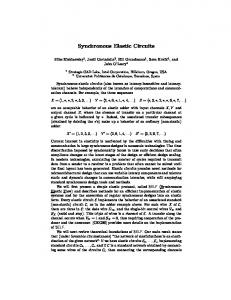
Fig. 1 depicts an example of an elastic implementation for transmitting data between two units. Each register has an associated valid bit (V ) that keeps track of the validity of the stored data. The clock signal is not explicitly shown and the enable signal (En) indicates when new data is stored into the register. The chain of AND gates
Data V
Valid
V
En
V En
En
V
Fig. 3.
Valid
Idle (I)
Valid Stop
i+k
...
wr
retry : B;
Combinational behavior:
Retry (R)
Vout = Fig. 2.
i+1
rd
Receiver
Sender
*
Receiver
Sender
Receiver
Sender
Transfer (T)
Valid
S out
State variables: B : array [0 . . . ∞] of data; rd, wr : N; Initial state: rd = wr = 0; retry = false; Invariant: wr ≥ rd
Data
*
Stop
V out
S in
B
A simple control for elastic data transmission.
Valid
V in
Interface of an EB with one input and one output channels. i
Stop
Data
D out
En
Stop Fig. 1.
D in
Output Environment
Data
Input Environment
receiver
sender
The SELF protocol.
8 < true
false
:
∗
if retry if rd = wr otherwise
Dout =
B[rd] ∗
if Vout otherwise
Sin = ∗
Sequential behavior:
manages the back-pressure generated by the receiver when it is not able to accept data (Stop = 1). The scheme in Fig 1 is not scalable due to the long combinational path from the receiver to the sender. When the pipeline is full, i.e. all V ’s are at 1, the delay of the Stop chain becomes critical.
wr+
rd + 1 if Vout ∧ ¬Sout otherwise rd wr + 1 if Vin ∧ ¬Sin = wr otherwise
rd+ =
retry+ = Vout ∧ Sout B+ [wr] = Din
Liveness properties (finite unbounded latencies):
A. The SELF protocol Data transfer between a sender and a receiver is performed by using the two control signals, Valid (V ) and Stop (S), that determine three possible states in the channel (see Fig. 2): •
•
•
Transfer (T), when V = 1 and S = 0, indicating that the sender is providing valid data and the receiver is accepting it. Idle (I), when V = 0, indicating that the sender is not providing any valid data. Retry (R), when V = 1 and S = 1, indicating that the sender is providing data but the receiver is not able to accept it.
The sender has a persistent behavior when a Retry cycle is produced: it maintains the valid data until the receiver is able to read it. The language observed at a SELF channel can be described by the following regular expression: (I ∗ R∗ T )∗
(1)
Absence of a subtrace RI implies the persistency of the behavior. Table I shows an example of a trace committing the SELF protocol and transmitting values A − D. When V = 0, the value at the data bus is irrelevant (cycles 0, 6 and 7). The receiver can issue a Stop even when the sender does not send valid data (cycle 7). The sender persistently maintains the same valid data as in the previous cycle during cycle 3, 4 and 9. Cycle Data Valid Stop State
0 ∗ 0 0 I
1 A 1 0 T
2 B 1 1 R
3 B 1 1 R
4 B 1 0 T
5 C 1 0 T
6 ∗ 0 0 I
7 ∗ 0 1 I
8 D 1 1 R
TABLE I A TRACE COMMITTING THE SELF PROTOCOL .
9 D 1 0 T
Forward latency: Backward latency: Fig. 4.
G(rd 6= wr =⇒ F Vout ) G(¬Sout =⇒ F ¬Sin )
Abstract model for an EB.
B. Specification of elastic buffers Figure 3 shows the interface of an elastic buffer (EB) with one input and one output channels. The extension to multi-input/output channels will be discussed in Section V-A. There can be different architectures to implement an EB trading-off area, delay and power consumption. For this reason, it is convenient to have a formal specification that can be used to verify that a particular implementation is valid refinement of the specification and can safely substitute another implementation. The abstract model for an EB is described in Fig. 4. Briefly, an EB is modeled as an unbounded FIFO that commits the SELF protocol at the input and output channels. The notation X + is used to represent the next-state value of variable X. The symbol ’∗’ represents a nondeterministic value (don’t care). B is an infinite array that stores the items written into the buffer, but not sent to the output yet. The variables wr and rd are the write and read indices of the array, respectively. The value k = wr − rd is the current number of items stored in the buffer. The retry variable remembers whether a transfer was attempted in the previous cycle. If retry is true, the same data item as in the previous cycle is issued and Vout = true. On the other hand, if the buffer does not contain any item (rd = wr), no transfer can be performed (Vout = false). Finally, the value Vout = ∗ represents the non-deterministic behavior of a buffer with finite but unbounded delay: the items stored in the buffer will eventually be transferred to the output after a finite unknown delay. Sin can non-deterministically stop any data transfer at the input channel. The behavior of the indices
D in Vin S in
M Fig. 5.
D out Vout S out
M
D in Vin S in
M
D out Vout S out
A A W 1R 1
The sequential composition of EBs refines an EB.
Dl
Data path
B
A
Sr Fig. 6.
B W 2R 1
Control Sl
W 2R 2
Dr Vr
Vl
B
Fig. 7.
A
B W 1R 2
Architectures for the data-path of EBs.
EB structure.
of the array is modeled by the rd+ and wr+ equations. When a data transfer is produced at the corresponding channel (V ∧ ¬S), the value of the index is incremented. Two liveness properties expressed in linear temporal logic [Pnu77] ensure finite response in the forward and backward directions: • data from the EB will eventually be sent to the output, and • a non-stop at the output will eventually be propagated to the input. C. Verification of EBs The model in Fig. 4 has been used as specification to check that every implementation presented in this paper is a refinement of this model. The proofs have been performed by using the features of refinement verification and data type reductions offered by SMV [McM99]. Let M be an abstract model of the EB. We have also verified that the sequential composition of two M is a refinement of M (see Fig. 5). This guarantees that EBs with specific depths can be built by the sequential composition of any implementations of EB that refines M presented in this paper. IV. I MPLEMENTATION OF ELASTIC BUFFERS The implementation of an EB can be decomposed into two parts: data-path and control (see Fig. 6). A. The data-path of the EBs Two important parameters of an EB are the forward, Lf , and backward, Lb , latencies. The Lf is the latency of forward propagation of the data and the Valid bit in in case the receiver is ready. The Lb is the backward latency for the stop signals. According to the unbounded specification of Fig. 4, Lf and Lb can be any value greater than zero (including non-deterministic values)1 . However, for performance optimization and for the ability to distribute the EBs across long communication channels and reuse them as sequential wire repeaters, the following constraint should be satisfied: Lf = Lb = 1 The capacity of an EB defines the maximal number of data items that can be simultaneously stored inside the buffer, e.g. the capacity of a regular flip-flop is 1. The following property holds: Property 4.1: The capacity of an elastic buffer, C, should satisfy the following constraint: C ≥ Lf + Lb 1 L = 0 and L = 0 would reduce the EB to an elastic channel. Having f b one of the latencies equal to 0 is possible in parts of the design, but does not scale, due to the long combinational delays and combinational cycles.
Therefore, for the case of interest (Lf = Lb = 1) the minimal possible capacity is C = 2. Hence the data path of an EB can be constructed with two storage cells and different write/read policies, e.g. the different number of read and write ports. Fig. 7 illustrates different options for the construction of an EB with respect to the numbers of write and read ports. For example, in the case of W1 R1 , writes always occur to the first cell (A), and reads always occur from the second cell (B), while in the case of W2 R2 both cells permit writes and reads. The following property holds: Property 4.2: A W1 R1 EB with Lf = Lb = 1 cannot be implemented using single-edge flip-flops controlled by the same frequency clock as used by the environment. Intuitively, this is because such a structure would have a latency of two between the write operation through the input channel and the read operation from the output channel. However, the construction of W1 R1 is possible with double-pumping, which would ensure that two data moves can occur during a clock cycle of the environment. Several implementation strategies can be considered: (1) two flops acting on different edges of the clock, (2) two flops acting on a single edge of a double frequency clock, and most notably, (3) simply by using two transparent latches of different polarity, similar to a master-slave structure, but with the independent control of enable signals for two latches. Obviously, the W1 R1 structure based on transparent latches is preferable according to most design metrics (area, delay, power). Other structures, that are based on single edge flops, can be used for high-level and performance modeling, formal verification (which often do not support transparent latches) and further be replaced with the equivalent W1 R1 structures in the later design stages. Flop-based structures can also be used in the design methodologies, which would not allow transparent latches (e.g., FPGAs). B. The control of the EBs As an example, Fig. 8 depicts the FSM specifications for two of the EBs shown in Fig. 7. The transparent latches are shown with single boxes, labelled with the phase of the clock, L (active low) or H (active high). The flip-flops are drawn as two transparent latches back-to-back. To simplify the drawing the clock lines are not shown. The signals going from the control units to the flip-flops and latches are the enable signals. Finally, an enable signal for transparent latches must be emitted on the opposite phase and be stable during the active phase of the latch. Thus, the Es signal for the slave latch is emitted on the L phase. The FSM specifications are similar to the specification of a 2-slot FIFO. The two versions of the FSMs are identical with respect to the protocol of the control channels, but perform different data exchanges in the data path. Let us consider, as an example, the W1 R1 buffer. In the Empty state no valid data is captured in the data-path. In the
Vl1 S l1
Dl !Vl*Sr/E1
Vl
Dr Vl*Sr/E1
Vl !Vl
Empty
Half
/E0
/Vr
Full !Sr/E0
!Vl*!Sr/E0
/Sl,Vr,Sel
E0 Vr
L
H
Half
Full
/Vr
/Sl,Vr
!Vl*!Sr
!Sr/Es
Sr
Dr
1
Es
1
Sl Sl
Es
Sel
E1
E0
Vl
Vr
Vl
Vr
Sl
Sr
Sl
Sr
Fig. 9.
W1 R1 (left) and W2 R1 (right) control implementation
VS
S r2 (c) Eager fork
Fig. 11.
Vr1 S r1
Vr2
Sr
Sl
Control specification for the W2 R1 and W1 R1 EBs
Em
Vl VS
Control
Vl*!Sr/Em,Es
E Vr1
Vl
Vr
Vl
(b) Lazy fork
S r1
L
Em
Vr2 S r2
Sl
Sr
Dl
S r1
(a) Join
Control
Vl*Sr/Em
Empty
Vl2 S l2
Sl
!Vl*Sr Vl/Em,Es
Fig. 8.
Sel
Vl
Vl*!Sr/E0
!Vl
E1
Sr
Vr1
Vr Sr
Vr2 S r2
(d) Optimized fork
Controllers for elastic Join and Fork structures.
Figure 11(b) depicts a lazy fork. The controller waits for both receivers to be ready (stop = 0) before sending the data2 . A more efficient structure shown in Fig. 11(c), the eager fork, can send data to each receiver independently as soon as it is ready to accept it. The two flip-flops are required to “remember” which output channels already received the data. This structure offers performance advantages when the two output channels have different backpressure. B. Optimization of elastic controllers
Half-full state, an output slave latch keeps valid data. In the Full state, both latches keep valid data and the EB requests the sender to stop. Figure 10 shows a linear elastic system with the two types of EBs from Fig. 8. Different types of EBs and controllers can be freely mixed since their channel interfaces and protocols are identical and commit the SELF protocol. The EB on the left uses the W2 R1 data-path. An implementation for the W1 R1 control shown in Fig. 9 (left) can be obtained directly from the FSM specification in Fig. 8 (bottom). By further splitting the two flip-flops into transparent latches and retiming, one can obtain a controller composed of two V S cells with latches of the opposite phase. The first of these V S cells is shown in the middle of Fig. 10. For the second cell, a modified equivalent implementation, V S 0 , is shown with the clock gating of both control latches.
Many forms of optimizing the elastic control structures are possible and some have been implemented by the authors. Local transformation of controllers have been illustrated in Fig. 10. Combining adjacent controllers opens up other possibilities for optimization. For example, an EHB followed by a fork is equivalent to another eager implementation of the fork shown in Fig. 11(d). Furthermore, constraints on the environment or the controller topology may enable the removal of redundant latches and gates. As an example, if the stop signal is never emitted by the receiver, the latches and combinational gates in the backward path of Fig. 10 can be removed and enable and forward logic can be simplified accordingly. We have developed a tool for automatic removal of the redundant transparent latches and flip-flops and logic gates from the elastic control layer using the SIS logic synthesis system [SSL+ 92].
V. A DVANCED ELASTIC CONTROL STRUCTURES
VI. A DESIGN EXAMPLE : THE DLX PIPELINE
A. Join and fork In general, EBs can have multiple input/output channels. This can be supported by using elastic Fork and Join control structures. Figure 11(a) shows an implementation of a Join. The output valid signal is only asserted when both inputs are valid. Otherwise, the incoming valid inputs are stopped. This construction allows to compose multiple Joins together in a tree like structure. receiver
sender Data
Data Valid
Valid Stop
Stop VS
Fig. 10.
VS’
Linear elastic pipeline with three versions of controllers
We use the DLX pipeline [HP90] to illustrate how elasticity can be used in microarchitectural design and to briefly review the design flow. Figure 12 depicts a block diagram of a possible implementation. It is assumed, for simplicity, that delay slots are used for handling data hazards and no forwarding is used. The shadowed boxes represent the registers that store the state of the microprocessor. From the control point of view, the register file and the instruction and data memories can be considered as combinational units. Figure 13(a) shows an abstraction of the pipeline in which only the channels among units are shown. The boxes represent the registers composed of two latches (master/slave). The diagram is equivalent for the datapath and control layers. The join and fork SELF controllers must be used when one unit has more than one input or output channel, respectively. Figures 13(b) and 13(c) show a latch-based diagram of the same pipeline after the insertion of “bubbles”. The shadowed latches are the ones initialized with valid data. This example illustrates that the insertion of bubbles does not affect the functionality of the system, although it may affect performance. Thus, the elastic architecture is 2 This
implementation is identical to the one presented in [JKB+ 02].
ADD
IF/ID 4 PC
EX/MEM
ID/EX
M u x
Zero?
Dl
MEM/WB
Branch taken
go
IR 11..15
M u x
Register file
M u x
16
Sign extend
Fig. 12.
clr EB
ALU
MEM/WB.IR
done
Dr
EB
IR 6..10
Instruction IR memory
Variable Latency Unit [0−k]
Data memory
M u x
Vl
Vr
Sl
Sr
Fig. 14.
Handling variable latency.
32
The DLX pipeline. (b)
V S
W 1R 1 control
(a) H L
H L L
H L
H L H
W 1R 1 control (join)
H L H L
V S
L
(c) PC
IF/ID
V S
ID/EX EX/MEM MEM/WB
W 1R 1 control
Fig. 15. H L
H L
H L
H
L H
Coarse-level control of functional blocks.
L H
L
Fig. 13.
The control layer for the DLX pipeline.
correct-by-construction with respect to inserting empty EBs. This feature is even more interesting when the bubbles can be inserted dynamically, as it will be discussed in the next section. The criteria for bubble insertion can be different: break long wires, cycle time optimization, power reduction, etc. Some of these criteria have been studied in [CSV03], [LK03] and the discussion on how to apply them is out of the scope of this paper. VII. H ANDLING VARIABLE LATENCY It is possible to insert bubbles dynamically by temporarily injecting valid = 0 and stop = 1 within any channel. Under the control of some supervisor algorithm the dynamic bubble insertion can lead to temporal and gradual shut-down/wake-up of computation and can be used for trading power vs. performance at different levels of granularity. Since the bubble insertion preserves correctness of the behavior it is also possible to convert some units of the system from fixed to variable latency. For instance, one could replace the 1-cycle ALU from the DLX pipeline by a variable-latency ALU optimized for the typical data case (e.g. short carry propagation). Such a telescopic ALU (cf. [BML+ 99]) calculating with latency 1 for the typical data mix, and with latency 2 for the rare data mix, can lead to performance improvement by designing the whole pipeline for a faster clock cycle, and to area reduction by reducing the number of logic gates per pipeline stage. An exact construction of the variable latency controller depends on the unit type (e.g. a multi-cycle combinational unit vs. a pipelined unit) as well as on the exact protocol that the unit follows. An example is shown in Fig. 14. The unit is assumed to have variable latency within 0 to k cycles. The valid signal sent at the input channel, Vl , is connected to the go input of the unit that starts the operation. The valid output on the right channel, Vr , is asserted when the unit completes the operation (done). Until then, the input channel
is stopped, which guarantees that the valid data value on the input channel is not changing (cf. the construction of the V S block). When the output EB is enabled the unit receives a clear signal (clr). This acknowledgement can be used to reset the internal state of the unit and to prepare it for the next operation. VIII. F ORMAL METHODS AND CAD TOOL SUPPORT A. Re-using existing CAD flows A crucial aspect in the adoption of elasticity by designers is the capability of using existing CAD flows. As shown in Sect. VI, the transformation of a synchronous system into an elastic system is straightforward by simply adding the control layer committing the protocol. The datapath remains intact, except for the fact that flip-flops are replaced with slightly different flip-flop cells with independent enabling for the master and slave latches (assuming the W1 R1 EBs are selected). Since the resulting design is still synchronous, conventional CAD tools for synthesis, analysis and simulation can be used. B. Coarse-level elasticity Figure 15 depicts an example on how elasticity can be inserted between blocks that can contain any kind of sequential behavior. In the example, the global clock is substituted by the gated clock generated by the elastic controllers (W1 R1 in this particular case). Thus, the elastic controller commands all the registers of the block with only one enable signal. To handle the backpressure, “ghost” latches must be added at the inputs of the blocks. These latches have the same polarity as the internal input latches of the block and do not introduce any extra latency, since they are redundant during the normal operation of the system. In the case that the blocks can be “opened” and optimized, the internal input latches can be simply removed. C. Correctness by construction In Sect. III, a formal model for the protocol and the EBs has been presented. This model is an abstraction that can be used for
Master M
IF/ID
Fig. 16.
IX. C ONCLUSIONS
S bubble
PC
Slave
ID/EX
token
EX/MEM
MEM/WB
A concurrent model for elastic designs.
A novel scheme for latency-insensitive design has been presented. It combines the modularity of asynchronous design with the efficiency of synchronous implementations. The little overhead introduced by the implementation of the elastic buffers makes this scheme attractive for different levels of granularity. Additionally, the correct-by-construction paradigm of this method enables its applicability at the latest stages of the design, when accurate delay estimations of data transfers have been performed, without any impact on the functionality of the system. R EFERENCES [BCK+ 04]
compositional verification of complex systems to guarantee correct system behavior. In particular, Fig. 13 illustrated the insertion of empty EBs into the DLX pipeline. The following property that guarantees soundness of this transformation holds: Property 8.1: The insertion of empty EBs in an elastic design preserves flow equivalence. Informally, flow equivalence [GTL03] between two designs guarantees that for every output the order of valid data items is the same3 . An example on what flow equivalence means is illustrated below.
[BML+ 99]
[Cha98] [CMSV01]
Synchronous behavior:
a1 a2 a3 a4 · · · ai · · · b1 b2 b3 b4 · · · bi · · ·
Elastic behavior:
a1 τ a2 τ τ τ a3 τ a4 · · · ai · · · b1 τ τ b2 τ b3 b4 · · · bi · · ·
[CN01]
[CSV02]
The synchronous behavior shows the trace of values observed at two registers, a and b, at every cycle. After making the design elastic, some don’t’ care values marked as invalid may appear (denoted as τ ). However, the order of valid data is preserved. It is important that the values at different registers may be shifted in time with respect to the pure synchronous behavior without affecting the functional correctness of the system, since any observer of both values would synchronize the corresponding valid tokens. While bubble insertion (empty EBs) is correct-by-construction, token insertion (non-empty EBs) requires care and possibly partial re-design similar to the standard pipelining.
[CSV03]
[GTL03] [HDGC04] [HP90] [JKB+ 02]
D. Performance evaluation Performance evaluation is another important aspect in system design. Abstractions of elastic systems can be derived by using concurrent models. In particular, the behavior of elastic systems can be modeled by using a subclass of Petri nets called marked graphs [Mur89]. As an example, Fig. 16 depicts the marked graph model corresponding to the DLX abstraction shown in Fig. 13(a). Each latch is modeled as a pair of complementary arcs in which the location of the token indicates whether the latch contains valid (token) or invalid (bubble) data. The transitions of the marked graph represent the computations between latches (empty if the transition is between a master and slave latch). Modeling systems with marked graphs enables the use of an extensive set of tools for the analytical performance analysis that can be effectively used at the earliest stages of the design. The authors have implemented computation of the effective cycle time for the SELF systems based on the separation analysis method from [Cha98]. 3 Other
authors call this property latency equivalence [SBM+ 05].
[LK03]
[McM99] [Mur89] [Pnu77] [SBM+ 05]
[SSL+ 92]
I. Blunno, J. Cortadella, A. Kondratyev, L. Lavagno, K. Lwin, and C. Sotiriou. Handshake protocols for de-synchronization. In Proc. International Symposium on Advanced Research in Asynchronous Circuits and Systems, pages 149–158. IEEE Computer Society Press, April 2004. L. Benini, G. De Micheli, A. Lioy, E. Macii, G. Odasso, and M. Poncino. Automatic synthesis of large telescopic units based on near-minimum timed supersetting. IEEE Transactions on Computers, 48(8):769–779, 1999. Supratik Chakraborty. Polynomial-Time Techniques for Approximate Timing Analysis of Asynchronous Systems. PhD thesis, Stanford University, August 1998. L. Carloni, K.L. McMillan, and A.L. Sangiovanni-Vincentelli. Theory of latency-insensitive design. IEEE Transactions on Computer-Aided Design, 20(9):1059–1076, September 2001. Tiberiu Chelcea and Steven M. Nowick. Robust interfaces for mixed-timing systems with application to latency-insensitive protocols. In Proc. ACM/IEEE Design Automation Conference, June 2001. L.P. Carloni and A.L. Sangiovanni-Vincentelli. Coping with latency in SoC design. IEEE Micro, Special Issue on Systems on Chip, 22(5):12, October 2002. L. Carloni and A.L. Sangiovanni-Vincentelli. Combining retiming and recycling to optimize the performance of synchronous circuits. In 16th Symp. on Integrated Circuits and System Design (SBCCI), pages 47–52, September 2003. P. Le Guernic, J.-P. Talpin, and J.-Ch. Le Lann. Polychrony for system design. Journal of Circuits, Systems and Computers, 12(3):261–304, April 2003. G.T. Hazari, M.P. Desai, A. Gupta, and S. Chakraborty. A novel technique towards eliminating the global clock in VLSI circuits. In Int. Conf. on VLSI Design, pages 565–570, January 2004. J.L. Hennessy and D. Patterson. Computer Architecture: a Quantitative Approach. Morgan Kaufmann Publisher Inc., 1990. Hans M. Jacobson, Prabhakar N. Kudva, Pradip Bose, Peter W. Cook, Stanley E. Schuster, Eric G. Mercer, and Chris J. Myers. Synchronous interlocked pipelines. In Proc. International Symposium on Advanced Research in Asynchronous Circuits and Systems, pages 3–12, April 2002. R. Lu and C.-K. Koh. Performance optimization of latency insensitive systems through buffer queue sizing of communication channels. In Proc. International Conf. Computer-Aided Design (ICCAD), pages 227–231, November 2003. Kenneth L. McMillan. Verification of infinite state systems by compositional model checking. In CHARME, pages 219–234, 1999. T. Murata. Petri Nets: Properties, analysis and applications. Proceedings of the IEEE, pages 541–580, April 1989. A. Pnueli. The temporal logic of programs. In Proceedings of the 18th IEEE Symposium on Foundations of Computer Science, pages 46–57, 1977. S. Suhaib, D. Berner, D. Mathaikutty, J.-P. Talpin, and S. Shukla. Presentation and formal verification of a family of protocols for latency insensitive design. Technical Report 2005-02, FERMAT, Virginia Tech, 2005. E. M. Sentovich, K. J. Singh, L. Lavagno, C. Moon, R. Murgai, A. Saldanha, H. Savoj, P. R. Stephan, R. K. Brayton, and A. Sangiovanni-Vincentelli. SIS: A system for sequential circuit synthesis. Technical report, U.C. Berkeley, May 1992.