unable to detect collisions since many designs lack touch sensors or bumpers. The .... occur briefly after the actual collision and can easily be distinguished from ...
Sensor-Actuator-Comparison as a Basis for Collision Detection for a Quadruped Robot Jan Hoffmann and Daniel G¨ohring Institut f¨ ur Informatik, LFG K¨ unstliche Intelligenz, Humboldt-Universit¨ at zu Berlin, Unter den Linden 6, 10099 Berlin, Germany http://www.aiboteamhumboldt.com
Abstract. Collision detection in a quadruped robot based on the comparison of sensor readings (actual motion) to actuator commands (intended motion) is described. Ways of detecting such incidences using just the sensor readings from the servo motors of the robot’s legs are shown. Dedicated range sensors or collision detectors are not used. It was found that comparison of motor commands and actual movement (as sensed by the servo’s position sensor) allowed the robot to reliably detect collisions and obstructions. Minor modifications to make the system more robust enabled us to use it in the RoboCup domain, enabling the system to cope with arbitrary movements and accelerations apparent in this highly dynamic environment. A sample behavior is outlined that utilizes the collision information. Further emphasis was put on keeping the process of calibration for different robot gaits simple and manageable.
1
Introduction
Many research efforts in mobile robotics aim at enabling the robot to safely and robustly navigate and to move about both known and unknown environments (e.g. the rescue scenarios in the RoboCup Rescue League [1], planetary surfaces [13]). While wheeled robots are widely used in environments where the robot can move on flat, even surfaces (such as office environments or environments that are accessible to wheelchairs [5]), legged robots are generally believed to be able to deal with a wider range of environments and surfaces. There are many designs of legged robots varying in the number of legs used, ranging from insectoid or arachnoid with 6, 8 or more legs (e.g. [2]), 4-legged such as the Sony Aibo [3], humanoid: 2-legged (e.g. [8]). Obstacle avoidance is often realized using a dedicated (360◦ ) range sensor [12]. Utilizing vision rather than a dedicated sensor is generally a much harder task since a degree of image understanding is necessary. For the special case of color coded environments, straight forward solutions exist that make use of the knowledge about the robot’s environment (such as the color of the surface or the color of obstacles [6]). If, however, obstacle avoidance fails, robots often are unable to detect collisions since many designs lack touch sensors or bumpers. The robot is unaware of the failure of its intended action and ends up in a situation it
2
a)
b)
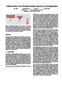
Fig. 1. a) A collision of two robots. Neither robot cannot move into the desired direction. Even worse, robots often interlock their legs which further prevent them from resolving the situation. b) Illustration of the DOFs of the Aibo. Each robot leg has three joints, two degrees of freedom (DOF) in the shoulder joint and one DOF in the knee joint, denoted Φ1 , Φ2 and Φ3 . Joints are labeled in the following way: F (ront) or H(ind) + L(eft) or R(ight) + Number of joint (1, 2, 3). Using this nomenclature, the knee joint of the highlighted leg in the above image is FR3.
is unable to resolve; it is - quite literally - “running into a wall” without noticing it. Apart from the current action failing, collisions (and subsequently being stuck) have severe impact on the robot’s localization if odometry is used to any degree in the localization process (as is the case in [11, 4]). For these approaches to be robust against collisions, they tend to not put much trust in odometry data . This work investigates the possibilities of detecting collisions of a Sony Aibo 4-legged robot using the walking engine and software framework described in [10]. The robot does not have touch sensors that can be used to detect collisions of it with the environment. As we will show, the servo motor’s direction sensors can be used for this task. Work by [9] shows that it is possible to learn servo direction measurements for different kinds of (unhindered) motions and use this to detect slippage of the robot’s legs and also to detect collisions of the robot with its environment. The approach to collision detection using the Aibo presented by [9] stores a large number of reference sensor readings and uses these to detect unusual sensor readings caused by collision and slip. Our approach differs in that we make assumptions about the robot motion that allows the robot to detect collisions by comparing the actuator command (desired motion) to the sensor readings (actual motion). The used set of reference values can be much smaller using this approach. We will show that the method is robust and also quickly adjustable to different walking gaits, robots, and surfaces. Section 4 compares the two approaches in detail.
3
joint anlge [mrad]
300 200 100 0 -100
50
100
150
actuator FL1 250 sensor300 FL1
350
400
-200 -300 -400 -500
t [8 ms]
Fig. 2. Sensor and actuator data of freely moving legs (in the air) at a desired ground speed of 75 mm/s. Sensor and actuator curves are almost congruent except for a slight phase shift.
2
Method
2.1
Comparison of the Actuator Signals and the Direction Sensor of the Robot’s Servos
The presented collision detection method is based on the comparison of actuator commands to direction sensor readings. Fig. 2 shows typical sensor measurements alongside actuator signals. It can be seen that for an unhindered period of movement T the sensor and actuator curve of a joint are congruent, i.e. they are of the same shape but shifted by a phase ∆ϕ . If ∆ϕ was zero, the area in between the two curves becomes minimal: Z
t0 +T
0≤
(a(t) − s(t + ∆ϕ))2 dt
(1)
t0
Tests using discrete time showed that collisions cause a discrepancy between actuator and sensor data which can be recognized by calculating the area between the sensor and actuator data. It was found that it was not necessary to sum over one complete period of the motion to detect collisions. Shorter intervals yield faster response times. Trading off response time and sensitivity to sensor noise, we found that 12 frames1 were sufficient. The last 12 frames are used to calculate the the Total Squared Difference (TSD ): T SDa,s (∆ϕ) =
t2 X
(ai − s(i+∆ϕ) )2
(2)
i=t1
Diagram 3 shows the TSD of the FL1 joint (left shoulder) for a robot colliding with the field boundary. The peaks in the TSD when the robot’s leg hits the boundary are clearly distinguishable. 1
A frame is an atomic step of the motion module; there are 125 frames per second, one frame is 8 ms long.
35000 30000
3500 3000
25000
2500
20000 15000
2000 1500
10000
1000
5000
500
0 -5000 0
0 50
100
150
200
250
300
350
-10000
400
joint angle [mrad]
Total Sq. Diff. [mrad2]
4
TSD for last 12 frames actuator, FL1 sensor FL1, phase shift = 8 frames
-500 -1000
t [8 ms]
Fig. 3. Sensor and actuator data of a collision with the field boundary walking forward at 150 mm/s. In the TSD the collisions can be seen as peaks in the curve. They occur briefly after the actual collision and can easily be distinguished from unhindered movements.
For classification of collisions the TSD is compared to a threshold. If the TSD is larger than this threshold, it is assumed that a collision has occurred. The thresholds for every motion component (i.e. walking forward/backward, walking sideways, rotation) are saved in a lookup table. For combined motions (e.g. walking forward and walking sideways at the same time) the different thresholds for each motion component are summed as described in section 3.3. 2.2
Aligning the Actuator and Sensor Curve
Fig. 4 shows the impulse response of one of the robot’s servo motors. It can be seen that the joint doesn’t move for about 5 frames (40 ms). Reasons for this are momentum and calculation time; the step height and the load that the joints have to work against also have an influence on the observed phase difference. After 5 frames the joint slowly starts moving and accelerates until it reaches its maximum speed after 8 frames. Just before reaching its destination, the joint angle changes are decreasing. This is due to the joint’s P.I.D. controller smoothing the robot’s motions.
joint angle [mrad]
2000 1600 actuator FL1 sensor FL1
1200 800 400 0 -400
0
10
20
40 30 t [8 ms]
50
60
Fig. 4. Sensor and actuator data for a rectangular actuator impulse. The actuator function jumps to its new value. The corresponding servo’s direction sensor readings are shown.
600 400 200 0 -200 -400 -600 -800 -1000
50
100
actuator FL1 sensor FL1 difference
t [8 ms]
joint angle [mrad]
joint angle [mrad]
5 600 400 200 0 -200 -400 -600 -800 -1000
50
100
t [8 ms]
Fig. 5. Left. Sensor and actuator data for walking freely at 150 mm/s. Actuator and sensor curve out of phase and the corresponding TSD Right. As above but phase shifted. Sensor function is shifted by 8 frames. The corresponding TSD now clearly shows collisions (peaks in the curve).
In figure 5, a) the TSD is shown for a sample motion. The smallest values of the TSD are found at the intersection of the two curves. Collision effects have little influence on the difference level. In b) actuator and sensor curves are aligned by shifting the sensor data curve left by 8 frames. The calculated TSD shows a strong response to collisions. Since phase shifts of varying length were observed, the 12 frames wide window of the TSD is calculated for several phase shifts ∆ϕ ranging from 6 to 15 frames. The smallest TSD is used to detect collisions. This approach eliminates phase shifts which are not caused by collisions and reduces the risk of wrongly recognized collisions (false positives). Due to the small number of possible values of ∆ϕ , real collisions still produce a strong signal. 2.3
Filtering of Actuator Input
The presented approach to collision detection works well under laboratory conditions, i.e. when applied to homogeneous motions with small, well defined motion changes (see sample application described in section 4). In real world applications, motion commands may change rapidly over time as the robot interacts with the environment. In the dynamic, highly competitive RoboCup domain, the robot changes its walking speed and direction quite frequently as determined by the behavior layer of the agent. Figure 6 shows the actuator commands for a robot playing soccer. Most of these changes are relatively small and unproblematic but some are too extreme to be executed by the servos, e.g. when the robot suddenly sees the ball and moves towards it at the highest possible speed. This is compensated by increasing the TSD threshold if the joint acceleration exceeds a certain value. This increased threshold is used only for some tenths of a second and then falls back to its initial level. 2.4
Threshold Calibration
The values of the thresholds are calibrated manually. They are measured for each of the elementary motions (forward/backward, sideways, rotation) in steps
6
joint angle [mrad]
600 400 200
sensor FL1
0 -200
10
30
50
70
90
110
130
150
170
actuator FL1
-400 -600 -800
-1000
t [8 ms]
Fig. 6. Actuator commands and sensor measurements during an actual RoboCup game. The robot is changing directions frequently. It can be seen that the servo is unable to perform the requested motions.
of 30 mm/s and 0.5 rad respectively. This adds up to a total of 40 measurements needed for operation. A threshold is determined by letting the robot walk freely and without collision or slip on the field freely for about three seconds while monitoring both motor commands and sensor readings. The TSD is calculated and the maximum TSD is used to derive a threshold value. The maximum TSD value that occurred is tripled; this means that for the robot to detect a collision, the TSD must be 3 times greater than the maximum TSD measured during calibration. In our experiments the calibration was done by hand since robot gaits do not undergo frequent change and the calibration process is performed quickly. We therefore did not see the need for automating the calibration process (given that an external supervisor has to make sure that no collisions occur during calibration anyway).
3
Detectability of Collisions During Directed Robot Locomotion
For different walking directions, collisions have different effects on the robot’s joints depending on how the joints are hindered in their motion. Therefore, the following cases were investigated. In our experiments, only the legs’ servos were used for collision detection. However, the robot’s head motors can also be used to directly detect whether a robot hits an obstacle with its head (or its head’s freedom of motion is otherwise impaired by an obstacle). In the detection of collisions, a trade off has to be performed between being sensitive to collisions and being robust against false positives (i.e. the detection of a collision where in reality the robot was moving freely). Since we wanted to avoid false positives, the threshold value for detecting collisions was raised at the cost of being less sensitive to detecting collisions. Furthermore, by integrating the information gathered over a short period of time, false positives can be suppressed. This, however, makes the robot less reactive.
7
3.1
Elementary Motions
Walking Forward or Backward. Collisions are easily detected in the front left or right shoulder joints FL1 and FR1 of the robot, depending on which of the legs hits the obstacle (see 1). This way collisions with the field boundary can be detected. Collisions with other robots can also be detected, but not as reliably because this sort of collision is of a much more complex type (the other robot may be moving, etc.). Collisions when walking backwards are slightly harder to recognize because of the particular position of the joints of the hind legs. This is due to the robot’s body being tilted forward and the backward motion not being symmetric to the forward motion. The rate of detection of collisions during forward movement was about 90%; for backward movement it was about 70%. Sometimes collisions would not be detected because the robot would push itself away from obstacles rather than being hindered in its joints’ motions. No false positives were observed. Walking sideways. Collisions which are occurring while the robot is walking sideways can be recognized best in the sideways shoulder joint θ2 (e.g. FL2 ) on the side where the robot hits the obstacle. This is not quite as reliable as in the case of forward motions because the Aibo loses traction more quickly when walking sideways for the gait that was used. About 70% percent of the actual collisions were detected. Some phantom collisions were detected at a rate of about 1-2 per minute. Turning. The same joints that are used to recognize collisions while moving sideways can be used to recognize collisions when the robot is turning. This way, a common type of collision can also be detected: The legs of two robots attempting to turn interlock and prevent the rotation from being performed successfully. How well this can be recognized depends on how much grip the robots have and on the individual turning (or moving) speeds. The detection rate of collisions and the rate of false positives is of the same order as when the robot is moving sideways. When raising the detection threshold to completely eliminate false positives for a robot rotating at 1.5 rad/sec, the rate of detection drops to about 50%. 3.2
Leg Lock
The before mentioned “leg lock” also occurs in situations where two robots are close to each other (e.g. when chasing the ball). Leg lock is detected in the same way collisions are. Therefore, “leg lock” is detected but cannot be distinguished from other collisions. 3.3
Superposition of Elementary Motions
While it is easy for the robot to recognize the above motions separately, it is harder to recognize collisions when motions are combined, e.g. when the robot
8
option collision-detector
option collision-detector initial
state initial if
left stuck
right stuck
else if
collision
collision
on front
on front
left
right
walk
left
right
stuck
stuck
else if
else
collision on head
initial
Fig. 7. Simple behavior option graph denoted in XABSL [7]. The robot walks forward until it hits an obstacle. It then turns away from it and continues walking in the new direction.
walks forward and sideways at the same time. For lower speeds, the resulting motions can be viewed as a superposition of the three elementary motions and the resulting threshold is approximated by the sum of the three individual thresholds: T (v, s, r) = T (v, 0, 0) + T (0, s, 0) + T (0, 0, r)
(3)
where v is the forward, s the sideways, and r the rotation component of the motion. For high speeds, the requested motions exceed the servos performance. To compensate for this, the collision thresholds are increased by multiplication by a scale factor f which is a function of v and s: f = f (v, s) =
( 1 v+s 100
if v < 50mm/s and s < 50mm/s otherwise
(4)
With this extension, the method can be applied to practically all kinds of robot motions and speeds that we observed in a RoboCup game.
4
Application and Performance
Sample Application. A simple behavior was implemented in the XABSL behavior mark up language [7]: The robot walks straight ahead; if it touches an obstacle with one of its front legs, it stops and turns left or right depending on the leg the collision was detected with. The robot turns away from where the collision occurred then continues to walk straight.
9
This simple behavior was tested on the RoboCup field in our laboratory and it was found to work reliably regardless of the type of collision (e.g. static obstacle or other robots). Collisions were detected with high accuracy. In some rare cases, collisions would not be detected immediately because of slippage of the robot’s legs. In these cases, the robot would recognize the collision after a brief period of time (order of tenths of seconds). RoboCup. As pointed out in [9], collision detection can be used to have the robot “realize” that an intended action was not successful and to have it act accordingly. It did, however, prove to be a difficult task to find the right action in a situation where two robots run into each other. This usually happens when they pursue the same goal, in our case when both are chasing the ball. Backing off gives the opponent robot an advantage, pushing it makes the situation worse. Current work investigates possible actions.
Other Approaches. A similar approach aimed at traction monitoring and collision detection was presented by another RoboCup team, the “Nubots”, in 2003 [9]. The method compares the current sensor data to reference sensor data. It does not use actuator commands for collision detection. The reference data consists of sensor data value and variance for a given motion type and is measured prior to the run. This training is done by measuring the sensor data of possible combinations of elementary motions. A four-dimensional lookup table is used to store the reference data. The four dimensions of the table are: forward/backward motion (backStrideLength), sideward motion (strafe), rotation (turn), and time parameter which stores information about the relative position of the paw in its periodic trajectory. Using this approach, the “Nubots” were able to detect collisions and slip. However, the four-dimensional lookup table requires a considerable amount of memory and training time (according to [9], 20x12x20x20 entries are used to fully describe a gait). During the training it is important that no collisions or slip occur. Using the lookup-table, no assumptions are made about similarities between actuator command and sensor readings. In contrast, our approach makes the assumption that there is a similarity between intended and actual motion and the variance of the sensor signal is constant for the entire period of the motion. Making these (fair) assumptions, very little memory is needed (40 parameters describe all possible motions) while still achieving good results in detecting obstacles. The parameter table needed for a given gait is generated quickly and easily.
5
Conclusion
With the presented method the robot is able to reliably detect collisions of a 4legged robot with obstacles on even surfaces (e.g. RoboCup field). Comparing the requested motor command to the measured direction of the servo motors of the robot’s legs was found to be an efficient way of detecting if the robot’s
10
freedom of motion was impaired. In a sample behavior, the robot turns away from obstacles after having detected the collision. The method was extended for use in RoboCup games. Here it is used to detect collisions (with players and the field boundaries) and to let the robot act accordingly and also to improve localization by providing additional information about the quality of current odometry data (validity). Further work will focus on finding appropriate reactions in competitive situations.
6
Acknowledgments
The project is funded by the Deutsche Forschungsgemeinschaft, Schwerpunktprogramm “Kooperierende Teams mobiler Roboter in dynamischen Umgebungen” (“Cooperative Teams of Mobile Robots in Dynamic Environments”). Program code used was developed by the GermanTeam, a joint effort of the Humboldt University of Berlin, University of Bremen, University of Dortmund, and the Technical University of Darmstadt. Source code is available for download at http://www.robocup.de/germanteam.
References 1. Robocup rescue web site. http://www.isd.mel.nist.gov/robocup2003. 2003. 2. J. E. Clark, J. G. Cham, S. A. Bailey, E. M. Froehlich, P. K. Nahata, R. J. Full, and M. R. Cutkosky. Biomimetic Design and Fabrication of a Hexapedal Running Robot. In Intl. Conf. Robotics and Automation (ICRA2001), 2001. 3. M. Fujita and H. Kitano. Development of an Autonomous Quadruped Robot for Robot Entertainment. Autonomous Robots, 5(1):7–18, 1998. 4. J.-S. Gutmann, W. Burgard, D. Fox, and K. Konolige. An experimental comparison of localization methods. Proceedings of the 1998 IEEE/RSJ Intl. Conference on Intelligent Robots and Systems (IROS’98), 1998. 5. A. Lankenau, T. R¨ ofer, and B. Krieg-Br¨ uckner. Self-Localization in Large-Scale Environments for the Bremen Autonomous Wheelchair. In Spatial Cognition III, Lecture Notes in Artificial Intelligence. Springer, 2002. 6. S. Lenser and M. Veloso. Visual Sonar: Fast Obstacle Avoidance Using Monocular Vision. In Proceedings of IROS’03, 2003. 7. M. L¨ otzsch, J. Bach, H.-D. Burkhard, and M. J¨ ungel. Designing agent behavior with the extensible agent behavior specification language XABSL. In 7th International Workshop on RoboCup 2003 (Robot World Cup Soccer Games and Conferences), Lecture Notes in Artificial Intelligence. Springer, 2004. to appear. 8. C. L. P. Dario, E. Guglielmelli. Humanoids and personal robots: design and experiments. Journal of Robotic Systems, 18(2), 2001. 9. M. J. Quinlan, C. L. Murch, R. H. Middleton, and S. K. Chalup. Traction Monitoring for Collision Detection with Legged Robots. In RoboCup 2003 Symposium, Lecture Notes in Artificial Intelligence. Springer, 2004. to appear. 10. T. R¨ ofer, I. Dahm, U. D¨ uffert, J. Hoffmann, M. J¨ ungel, M. Kallnik, M. L¨ otzsch, M. Risler, M. Stelzer, and J. Ziegler. GermanTeam 2003. In 7th International Workshop on RoboCup 2003 (Robot World Cup Soccer Games and Conferences), Lecture Notes in Artificial Intelligence. Springer, 2004. to appear. more detailed in http://www.robocup.de/germanteam/GT2003.pdf.
11 11. T. R¨ ofer and M. J¨ ungel. Vision-Based Fast and Reactive Monte-Carlo Localization. IEEE International Conference on Robotics and Automation, 2003. 12. T. Weigel, A. Kleiner, F. Diesch, M. Dietl, J.-S. Gutmann, B. Nebel, P. Stiegeler, and B. Szerbakowski. CS Freiburg 2001. In RoboCup 2001 International Symposium, Lecture Notes in Artificial Intelligence. Springer, 2003. 13. K. Yoshida, H. Hamano, and T. Watanabe. Slip-Based Traction Control of a Planetary Rover. In Experimental Robotics VIII, Advanced Robotics Series. Springer, 2002.