10 Oct 2013 ... Sensor arrays from multicomponent micropatterned nanoparticles and graphene.
View the table of contents for this issue, or go to the journal ...
Home
Search
Collections
Journals
About
Contact us
My IOPscience
Sensor arrays from multicomponent micropatterned nanoparticles and graphene
This content has been downloaded from IOPscience. Please scroll down to see the full text. 2013 Nanotechnology 24 444010 (http://iopscience.iop.org/0957-4484/24/44/444010) View the table of contents for this issue, or go to the journal homepage for more
Download details: IP Address: 129.22.1.19 This content was downloaded on 30/11/2013 at 21:42
Please note that terms and conditions apply.
IOP PUBLISHING
NANOTECHNOLOGY
Nanotechnology 24 (2013) 444010 (7pp)
doi:10.1088/0957-4484/24/44/444010
Sensor arrays from multicomponent micropatterned nanoparticles and graphene Enoch Nagelli1 , Rajesh Naik2 , Yuhua Xue1 , Yunxiang Gao1 , Mei Zhang1 and Liming Dai1 1 2
Case School of Engineering, Case Western Reserve University, Cleveland, OH 44106, USA Materials and Manufacturing Directorate, Air Force Research Laboratory, Dayton, OH 45433, USA
E-mail:
[email protected]
Received 17 March 2013, in final form 9 May 2013 Published 10 October 2013 Online at stacks.iop.org/Nano/24/444010 Abstract A novel approach for multicomponent patterning metal/metal oxide nanoparticles on graphene was developed, which involves region-specific plasma treatment, followed by region-selective substrate-enhanced electroless deposition of Au nanoparticles and solution alkalization of ferrous chloride tetrahydrate in the presence of ammonia into Fe3 O4 nanoparticles. The resultant Fe3 O4 /Au multicomponent micropatterned-graphene films were found to be highly selective sensor arrays for detecting low levels of chemical vapor molecules at ppm levels. This novel concept could be applied to the development of various multicomponent patterned nanomaterials for many potential applications, ranging from nanoscale region-specific chemical-/bio-sensor arrays to multifunctional optoelectronic devices. (Some figures may appear in colour only in the online journal)
1. Introduction
films in pre-patterned structures. Among methods reported for producing graphene films, the mechanical cleavage of HOPG [6] and solution exfoliation of graphite crystals [7, 8] are the most widely used methods to produce singleand few-layer graphene sheets of high quality. However, subsequent deposition of materials prepared by these methods often lead to physically adsorbed graphene films of relatively weak interactions with substrates, which may be removed easily during the device fabrication and/or lead to a poor device performance. Therefore, several different methods have been developed for fabricating micropatterned-graphene films, including contact printing using a HOPG stamp made by O2 reactive ion etching [9, 10], chemical vapor deposition through a mask [11], and electron-beam lithography through a hydrogen silsesquioxane mask [12]. Nevertheless, all of the above-mentioned studies deal with only single component patterning. The development of graphene micropatterns in which multicomponents are interposed in a controllable fashion is important to multifunctional applications [1, 2]. As far
Multicomponent micropatterned hybrid nanostructures arranged in a controllable manner have attracted a significant amount of attention due to synergistic properties arising from spatially well-defined different components [1, 2]. Compared to simple single component systems, multicomponent patterns have novel multifunctionalities through the integration of different functional components into designed complex structures [2]. On the other hand, the fabrication of micropatternedgraphene films is essential for the development of graphenebased devices [3]. Owing to its unique properties, such as large surface area, high optical transparency, high electron mobility, and superior electronic properties [4, 5], graphene has been regarded as a nanomaterial with various promising applications, including high-performance nano/microscale integrated sensing devices, new materials for energy conversion and storage, and multifunctional materials for thermal management, to name a few. Many of these and other potential applications require the formation of graphene 0957-4484/13/444010+07$33.00
1
c 2013 IOP Publishing Ltd Printed in the UK & the USA
Nanotechnology 24 (2013) 444010
E Nagelli et al
as we are aware, however, multicomponent micropatternedgraphene films with different nanocomponents regionspecifically interposed in a controllable fashion have not been produced, presumably due to technical difficulties. Here, we report a simple, but effective, spatially controlled method for multicomponent micropatterning graphene films with metal/metal oxide nanoparticles interposed in a controllable fashion. Among many potential applications, the resultant Fe3 O4 /Au multicomponent micropatterned-graphene films were demonstrated to be highly selective sensor arrays for detecting low levels of chemical vapor molecules.
2. Experimental section The fabrication of multicomponent metal-nanoparticlepatterned-graphene films consists of four simple steps, as illustrated in scheme 1. Chemiresistive materials have been employed to detect toxic industrial chemicals (TICs) and explosives and have been shown to be suitable for gas sensing applications. For example, toxic chemicals (e.g., formaldehyde, CH2 O) can exist in building infrastructure materials and in the combustion gas of organic materials. Despite the efforts of many research groups in developing gas sensors, challenges still remain related to selectivity, sensitivity, and stability. In order to achieve chemical selectivity and stability for multiple gas sensing applications, in this study, we deposited graphene on a SiO2 /Si substrate by CVD and region-specifically decorated it with metal and metal oxide nanoparticles for sensing. As shown in scheme 1, a graphene–metal nanoparticle array was fabricated with the oxygen plasma functionalization through a physical mask (e.g., TEM grid), followed by depositing Fe3 O4 nanoparticles and the substrate-enhanced electroless deposition (SEED) [11, 12] of metal (e.g., Au) nanoparticles on graphene in the non-plasma-treated areas (note, a very short plasma time has been used to minimize the O2 -plasma etching effect). Deposition of Fe3 O4 nanoparticles was conducted through an alkalization reaction of ferrous ions with ammonium hydroxide (NH4 OH) in the presence of ammonia to form Fe3 O4 nanoparticles within the plasma-treated areas through the hydrophilic–hydrophilic interaction. After removing the mask, the graphene area under the mask can be decorated with Au nanoparticles by using the SEED technique. Metal ions with a redox potential lower than that of graphene can be readily reduced into metal nanoparticles on the graphene layer [11, 12]. The region-selective co-deposition of Fe3 O4 and Au nanoparticles into the graphene micropattern can produce region-specifically interposed active sites for selective adsorption and desorption of gas molecules. The newly developed Au and Fe3 O4 nanoparticle-decorated graphene hybrid device can be used for selective chemical vapor sensing through monitoring conductivity changes caused by the charge-transfer interaction with gas molecules.
Scheme 1. (A) Fabrication of multicomponent metal-nanoparticlepatterned-graphene films: (1) chemical vapor deposition (CVD) synthesized graphene on 300 nm sputtered Ni catalyst on a SiO2 /Si substrate, (2) oxygen RF plasma (0.04 mbar, 10 W) was used to functionalize the exposed areas of the graphene with oxygen groups through the TEM grid as a physical mask for 20 s, (3) Fe3 O4 nanoparticles are formed on the O2 -plasma functionalized areas of graphene via the hydrophilic–hydrophilic interaction, followed by the alkalization of ferrous chloride tetrahydrate in the presence of ammonia, and (4) after removal of the TEM grid mask, 5 mM aqueous solution of HAuCl4 was used for SEED of Au nanoparticles.
a SiO2 /Si substrate, which was then heated up to 1000 ◦ C within a quartz tube furnace under a high-purity argon atmosphere. Thereafter, a hydrocarbon rich reaction gas mixture (CH4 :H2 :Ar, 50:65:200 standard cubic centimeters per minute) was introduced into the quartz tube and kept flowing for 5 min, followed by purging with a flow of Ar for another 5 min. The sample was then rapidly moved out from the furnace under Ar protection. 2.2. Oxygen plasma functionalization Plasma functionalization was carried out on a custom-built plasma apparatus powered at 13.56 MHz, 200 W (Cesar 133 RF power generator) and a pressure of 100 Pa with O2 flow [13]. The plasma functionalization was applied to the exposed areas of the graphene film through the TEM grid.
2.1. Preparation of graphene film Chemical vapor deposition was used to develop graphene films by sputtering a thin layer of nickel film (300 nm) on 2
Nanotechnology 24 (2013) 444010
E Nagelli et al
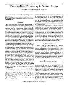
Figure 1. (A) AFM image of the pristine graphene, (B) typical Raman spectra of the pristine graphene recorded at some spots (top panel) and many different locations (bottom panel), and contact angle (deg) of H2 O on graphene (C) before and (D) after the O2 plasma functionalization.
5 mm apart from each other across the patterned-graphene surface for electrical contacts. The patterned-graphene sensor was then exposed to chemical vapors (e.g., ethanol) in a one-neck flask containing the chemical solvent for resistance measurements with a two-probe dc resistance meter (Dual Display Multimeter, Fluke 45) under ambient conditions [17]. For verification, four-probe dc surface resistance measurements were carried out under the same condition. There was no obvious difference between the two-probe and four-probe results, indicating that good contacts were made with the patterned-graphene film. The resistance of the external wires is insignificant due to their relatively short length [17].
2.3. Multicomponent metal and metal oxide nanoparticles deposition Nanoparticles of Fe3 O4 were synthesized by hydrolysis of an aqueous solution containing iron salts and a base at room temperature in ambient atmosphere [14]. Ferrous chloride (FeCl2 ·4H2 O, 0.05 M) was used as the iron salt and ammonium hydroxide (NH4 OH, pH = 12) was used as the base for the reaction [14]. The plasma patterned-graphene film was immersed in the iron salt (ferrous chloride) solution mixed with an aqueous solution of ammonium hydroxide and a precipitate was immediately produced in the plasma-treated areas of graphene through the hydrophilic–hydrophilic interaction. The pH value of the reaction bath was 12. The precipitate was washed with ultrapure water several times to remove excess amine molecules. After removing the mask (scheme 1), SEED was used to deposit Au nanoparticles on the Ni-supported patterned-graphene films by reducing an aqueous solution of HAuCl4 (5 mM) on the surface of the patterned graphene. The nanoparticle growth process is controlled by diffusion of AuCl−1 4 from the bulk solution to the non-plasma-treated areas of the graphene/solution interface [15, 16]. Since this is a diffusion controlled process, smaller particles often show a faster growth than larger particles due to relatively more surface-receiving sites for the metal ions [15, 16].
3. Results and discussion A typical atomic force microscope (AFM) image for the pristine graphene is given in figure 1(A), which shows a smooth surface with some wrinkled structures. Figure 1(B) represents the corresponding Raman spectra, showing the co-existence of single-layer graphene (top panel, figure 1(B)) and multilayer (2–5 layers) graphene (bottom panel, figure 1(B)) [18, 19]. The corresponding G-band and 2D-band Raman mapping (not shown) indicates a large area of good homogeneity for the multilayer graphene film, with some randomly scattered single-layer graphene spots. As expected, the O2 -plasma treatment has made the surface more hydrophilic with respect to the pristine graphene surface (figures 1(C) and (D)).
2.4. Vapor sensor measurements The patterned-graphene hybrid sensors were developed by thermally evaporating 2 mm strips of sputter-coated Al about 3
Nanotechnology 24 (2013) 444010
E Nagelli et al
Figure 2. SEM images of the multicomponent patterned graphene. (A) and (D) Hexagonally patterned graphene with Fe3 O4 nanoparticles within the hexagon and Au nanoparticles deposited in the outer border; enlarged views of the Fe3 O4 nanoparticle deposited areas (B) and (C) and Au nanoparticle deposited areas (E) and (F) on the multicomponent graphene hexagonal pattern. EDX mapping of (G) Fe and (H) Au.
displays a doublet peaks at 87.8 and 83.4 eV for Au 4f5/2 and Au 4f7/2 with, respectively (figure 4(D)). In addition, the sharp peak at 284.5 eV (figures 4(A) and (B)) can be assigned to graphitic carbon while the predominant peak at 541.8 eV is attributable to O1s from the lattice oxygen of Fe3 O4 (figures 4(A) and (B)). Decoration of carbon nanomaterials (e.g., CNTs, graphene) with metal or semiconducting particles can lead to sensitive chemical vapor sensors. For instance, Au- and Pt-decorated CNTs elicited a response (1R/R0 ) to NO2 and NH3 , which was six to eight times higher than that of pristine CNTs due to a spillover effect at the metal nanoparticles [20, 21]. Electron transport through the newly developed multicomponent metal-nanoparticle-patterned-graphene film can be highly sensitive to adsorbed molecules [20, 21], enabling the development of a sorption-based sensor array for detecting low levels of vapor using low-power electronics. Moreover, the resultant multicomponent graphene film hexagonally patterned with Fe3 O4 /Au nanoparticles can be potentially used for region-specific adsorption of analytes from vapor mixtures, and hence region-sensitive sensor arrays. The vapor sensor tests were performed at room temperature using
Figure 2 shows scanning electron microscopic (SEM) images for the Au and Fe3 O4 nanoparticle multicomponent micropatterns. As can be seen, the resultant micropattern is a close replication of the TEM grid structure with both Au and Fe3 O4 nanoparticles registered well in respective areas. This is further confirmed by the corresponding EDX mapping of Fe and Au elements shown in figures 2(G) and (H), respectively. Figure 3 shows the atomic force microscope (AFM) images of Fe3 O4 nanoparticles (A) and (B) in the inner area of hexagonally patterned graphene and Au nanoparticles (C) and (D) in the outer region of the hexagonal graphene frame. Both the SEM and AFM images show aggregated structures formed from smaller particles. X-ray photoelectron spectroscopic (XPS) analysis was carried out to obtain further information on the surface composition. Figures 4(A) and (B) show the XPS survey spectrum for the graphene/Fe3 O4 and multicomponent patterned graphene/Fe3 O4 /Au, respectively. The peaks at 710.0 and 723.5 eV in the high-resolution Fe 2p scan can be attributed to the levels of Fe 2p3/2 and Fe 2p1/2 in the multicomponent graphene film, respectively (figure 4(C)). The corresponding high-resolution XPS spectrum for Au 4
Nanotechnology 24 (2013) 444010
E Nagelli et al
Figure 3. AFM images of Fe3 O4 nanoparticles (A) and (B) in the inner area of hexagonally patterned graphene and Au nanoparticles (C) and (D) in the outer region of the hexagonal graphene frame.
Figure 4. XPS survey spectra of (A) graphene/Fe3 O4 and (B) multicomponent patterned graphene/Fe3 O4 /Au, along with the high-resolution spectra of (C) Fe 2p, (D) Au 4f.
ethanol, methanol, and formaldehyde as candidate vapors. Figure 5 shows the response–recovery curves of the Fe3 O4 /Au patterned-graphene gas sensor array. The sensor showed very
fast response and recovery with a good reproducibility. A comparison study on the sensor performance shows that the patterned multicomponent sensor is at least 2× more 5
Nanotechnology 24 (2013) 444010
E Nagelli et al
Figure 5. Dynamic response–recovery curves of gas sensors based on the multicomponent Fe3 O4 /Au patterned graphene and the corresponding single component sensors to (A) ethanol, (B) methanol, and (C) formaldehyde upon exposure to vapor with time intervals ‘on’ and ‘off’. Resistance (%) = (Rvapor − R0 )/R0 × 100%, where R0 and Rvapor are the resistances of the sensor before and after exposure to ethanol, methanol, and formaldehyde vapor, respectively.
Figure 6. Dynamic response–recovery curves of gas sensors based on Fe3 O4 /graphene and Au/graphene to (A) formaldehyde and (B) ethanol upon exposure to vapor with time intervals ‘on’ and ‘off’, demonstrating the selectivity. Resistance (%) = (Rvapor − R0 )/R0 × 100%, where R0 and Rvapor are the resistances of the sensor before and after exposure to ethanol and formaldehyde vapor, respectively.
sensitive than either of the single component sensors toward vapor molecules, suggesting a synergetic effect arising from the multicomponent micropatterned structure. Furthermore, figure 6 shows the selective sensing of formaldehyde and ethanol by the Fe3 O4 /graphene and Au/graphene sensor, respectively. The higher magnitude in the resistance response of the Au-modified and Fe3 O4 -modified graphene sensor to ethanol and formaldehyde, respectively, was caused by the specific sensing effect of the Au and Fe3 O4 nanoparticles
to the specific chemical vapor. Thus, the multicomponent Fe3 O4 /Au patterned-graphene sensor array could be used for sensing both formaldehyde and ethanol even in a region-specific manner. Our preliminary results indicate that similar device performance was obtainable even after transferring the multicomponent patterned graphene without the Ni support onto an insulator silicon wafer, indicating that the Ni film under graphene did not play a significant role, if any, in the sensing process. 6
Nanotechnology 24 (2013) 444010
E Nagelli et al
4. Conclusions
[2] Qu L, Vaia R A and Dai L 2011 ACS Nano 5 994 [3] Liu L, Zorn G, Castner D G, Solanki R, Lerner M L and Yan M 2010 J. Mater. Chem. 20 5041 [4] Geim A K and Novoselov K S 2007 Nature Mater. 6 183 [5] Geim A K 2009 Science 324 1530 [6] Novoselov K S, Geim A K, Morozov S V, Jiang D, Zhang Y, Dubonos S V, Grigorieva I V and Firsov A A 2004 Science 306 666 [7] Hernandez Y et al 2008 Nature Nanotechnol. 3 563 [8] Park S and Ruoff R S 2009 Nature Nanotechnol. 4 217 [9] Li D S, Windl W and Padture N P 2009 Adv. Mater. 21 1243 [10] Cong C X, Yu T, Ni Z H, Liu L, Shen Z X and Huang W 2009 J. Phys. Chem. C 113 6529 [11] Qu L and Dai L 2005 J. Am. Chem. Soc. 127 10806 [12] Qu L, Dai L and Osawa E 2006 J. Am. Chem. Soc. 128 5523 [13] Qu L, Dai L, Stone M, Xia Z and Wang Z L 2008 Science 322 238 and references cited therein [14] Dan Y, Kybert N J, Luo Z and Charlie Johnson A T 2009 Nano Lett. 9 1472 [15] Zhu Y, Murali S, Ca W, Cai X, Li X, Suk J W, Potts J R and Ruoff R S 2010 Adv. Mater. 22 3906 [16] Schedin F, Giem A K, Morozov S V, Hill E W, Blake P, Katsnelson M I and Novoselov K S 2007 Nature 6 652 [17] Wei C, Dai L, Roy A and Tolle T B 2006 J. Am. Chem. Soc. 128 1412 [18] Ferrari A C et al 2006 Phys. Rev. Lett. 97 187401 [19] Allen M, Tung V C and Kaner R B 2010 Chem. Rev. 110 132 [20] Kauffman D R and Star A 2008 Angew. Chem. Int. Edn 47 6550 and references cited therein [21] Robinson J T, Perkins F K, Snow E S, Wei Z and Sheehan P E 2008 Nano. Lett. 8 3137
We have, for the first time, demonstrated that regionspecific plasma etching, in conjunction with region-selective metal/metal oxide nanoparticle deposition, can be used to fabricate multicomponent graphene micropatterns with metal/metal oxide nanoparticles interposed within the patterned structure in a controllable fashion, and that the resultant Fe3 O4 /Au multicomponent micropatterned graphene films can be used as sensor arrays for detecting low levels of chemical vapor molecules, even in a region-selective manner. The concept developed in this study for multicomponent patterning of nanoparticles on graphene is highly generic, which could be regarded as a general approach toward various multicomponent patterned nanomaterials for many potential applications, ranging from nanoscale (e.g., by e-beam lithography) region-specific chemical-/bio-sensor arrays to multifunctional optoelectronic devices.
Acknowledgment This work was partially supported by AFRL/DAGSI (RX2CWRU-10-1) and DOD-AFOSR-MURI (FA9550-12-1-0037) projects.
References [1] Yang J, Dai L and Vaia R A 2003 J. Phys. Chem. B 107 12387
7