generates the maps by analyzing the robot's self-description and inferring the pose of .... framework as a central component for general data storage. Semantic.
Server-sided Automatic Map Transformation in RoboEarth Alexander Perzylo� , Bj¨orn Schießle∗ , Kai H¨aussermann∗ , Oliver Zweigle∗ , Paul Levi∗ , Alois Knoll�
Abstract— RoboEarth aims at providing a distributed cloudbased web platform from robots for robots that is publicly accessible and enables robots to autonomously share knowledge among each other and to generate new knowledge from previously stored data. As a result robots don’t have to gain the same knowledge over and over again, but can build upon it right from the start. Currently, shareable data are abstract task descriptions, object models and environment maps. In this paper we describe RoboEarth’s approach to automatically and transparently generate 2D maps for localization and navigation, which are extracted from shared 3D maps and suited for a specific robot configuration. The parameters of the map generation process get inferred from a robot’s semantic self-description. Using RoboEarth for knowledge generation enables simple platforms with low computational power to execute complex tasks in complex environments. Furthermore the approach effectively simplifies the time consuming process of generating new maps every time a new robot platform with different specifications is used.
I. INTRODUCTION In future days mobile intelligent robots might become daily companions in our lives. In this scenario they will probably start with populating environments like hospitals and nursing homes for the elderly. They will be asked to perfom complex tasks like mobile manipulation, which necessitates localization and navigation among other things. The RoboEarth platform is being developed to prove that a common knowledge base coupled with the concept of cloud robotics speeds up learning and adaption to new circumstances [1] [2]. RoboEarth assists robots in achieving their goals by providing means to autonomously share re-usable knowledge using an open system, which can be accessed from all over the world using the World Wide Web. Robots may request task descriptions, that enable them to execute a task they haven’t been programmed for beforehand. In the RoboEarth context they are called action recipes. Objects that are referenced from within action recipes are linked with corresponding detection models that can be downloaded from RoboEarth in order to enable robots to interact with those objects. For determining whether a certain type of robot is capable of using an action recipe we use the RoboEarth language to state the robot’s capabilities and the action recipes’ requirements. This permits to check if and what components are missing on a robot for it to be able to execute the action recipe. Missing components can be searched for on � Alexander Perzylo and Alois Knoll are with the Technische Universit¨at M¨unchen, Department of Robotics and Embedded Systems, D-85748 Garching bei M¨unchen, Germany. ∗ Bj¨ orn Schießle, Kai H¨aussermann, Oliver Zweigle and Paul Levi are with the Universit¨at Stuttgart, Department of Image Understanding, D-70569 Stuttgart, Germany.
RoboEarth again [3]. As involved objects are often found at specific locations, the robot might also need to download environmental maps from RoboEarth. This includes maps for localization and navigation and semantic maps, which basically are lists of localized objects. By obtaining missing maps the robot learns where to look for objects and how to get there. Next to a shared database system, RoboEarth provides web services for solving issues, for which the robot doesn’t have the needed computational power or lacks required algorithms, e.g. logical reasoning about the knowledge stored in RoboEarth. In this paper we want to introduce one of RoboEarth’s web services: the RoboEarth Map Service. Given a pre-shared 3D map for a certain environment, which was submitted by an arbitrary robot, any robot providing a semantic model of itself can request 2D maps for localization and navigation in that environment. The RoboEarth map service automatically generates the maps by analyzing the robot’s self-description and inferring the pose of the robot’s base laser scanner and overall bounding box. If suitable maps are already stored in RoboEarth, due to the robot having requested maps for the same environment before, they will be directly sent to the robot. Otherwise a 3D map for the requested environment is searched for. If it is found, the RoboEarth map service extracts a 2D slice out of the 3D map at the height above ground of the base laser scanner. This slice is stored again in RoboEarth as 2D map intended to be used for localization. A second operation performs a 2D projection of parts of the 3D map that are determined by the bounding box of the robot. This 2D map might contain obstacles the robot’s base laser scanner cannot see and is intended to be used for path planning and navigation. II. R ELATED W ORK In order to allow indoor navigation, many robotic systems use range sensors, which take measurements in a plane parallel to the floor (for an overview see Thrun [4]). However, the information provided by a 2D scanner is usually insufficient, because of dynamic objects or noise. The existence of humans or other dynamic objects is typical for real world environments and makes the modeling of the environment and the navigation a challenging task. To handle completely unstructured environments, 3D sensors where proposed for navigation to build 3D or 2.5D maps for navigation [5], [6], [7], [8]. Because the navigation process that bases on 3D or 2.5D maps is computationally very expensive, a combination of 3D sensors and 2D SLAM algorithm was introduced [9], which bases on ”leveled
range scans”. This approach enables the system to use 3D perception to cope with dynamic objects and noise and furthermore, to use less complex 2D navigation algorithms. However, a computationally intensive process still remains locally on the robots. Thus, our approach includes the concept of cloud computing with the basic idea to offload the demanding map generation process to RoboEarth. Particularly in the domain of robotics, there exists an increasing interest in cloud computing. The researchers of [10] propose a framework, which allows robots to generate 3D maps of their environments on a cloud infrastructure, instead of locally on their on-board computers, whereas the researchers of [11] propose a more general concept to perform speech recognition, face detection, and other tasks on a cloud service. Furthermore, the concept of [12] involves a software framework, which attempts to offload data and computationally intensive workloads from robots to a distributed system shared by multiple clients. The framework allows to perform heavy computing tasks and enables the exchange of relevant data of the robot. In general all presented available cloud robotic approaches are very specific related to their practices, robots and interfaces. In contrast RoboEarth’s map service is a more general and open approach, which may be used for numerous different applications. The remainder of this paper is structured as following. Section III presents a brief overview about RoboEarth and the general architecture of the framework. Furthermore, the chapter describes how the map service is integrated into RoboEarth to allow robots from all over the world to use it. Section IV focuses on the proposed description format for the robots and the corresponding hardware description. Section V explains the technical process of extracting and storing 2D maps from a given 3D map. Section VI describes a demonstration and the successful evaluation of our proposed framework. Finally, Section VII concludes the paper and gives a brief outlook on future work. III. ROBO E ARTH W EB P LATFORM RoboEarth provides data storage and computational power for robots all over the world as a service based on the principles of cloud computing [13]. It enables robots to share reusable knowledge about actions, objects and environments and leverage the computational power of RoboEarth to execute algorithms which would exceed the capabilities of a single robot. This enables robots to perform tasks, detect objects and operate in environments they have never experienced before. A. General architecture of RoboEarth To store a huge amount of data and to provide the necessary computational power the system is build using the principles of cloud computing. For the underlying system the Apache Hadoop framework [14] for reliable, scalable and distributed computing is used. This allows for easily upgrading the system regarding hard disk capacity and
External Interfaces dp 1
kinect2revision
... dp N
Interface 1
Data Processors
Reasoning Server (Sesame)
Data Processing Daemon
OSM
Distributed Storage (Hadoop)
...
Interface N
Web/REST Interface (Python Django)
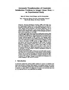
Fig. 1. Overall architecture of the RoboEarth web platform. The platform is based on the principles of cloud computing and uses the Apache Hadoop framework as a central component for general data storage. Semantic descriptions are stored in a Sesame repository, which provides querying and reasoning capabilities. RoboEarth also offers an infrastructure for server side data processors and services and implements a web interface which grants access to humans and robots.
computational power, whenever it might become neccessary. Furthermore the framework provides well known and tested components to store and compute a large amount of data records. The NoSQL database HBase is based on the principles of Google’s BigTable [15] which is designed to operate on petabytes of data across thousands of commodity servers. For computational tasks Hadoop implements MapReduce, originally designed by Google [16]. Figure 1 illustrates the overall architecture of the web platform of which Apache Hadoop is a central component. Another important part of the system is the Sesame framework [17] which provides means to store and query semantic descriptions and do server side reasoning. In particual, this enables RoboEarth to handle queries specified with the Sesame RDF Query Language (SeRQL) [18] to select the right data sets and improve the capabilities of server side services and data processors. With server side services and data processors RoboEarth enables robots to access the computational power of the web platform. RoboEarth provides well defined REST-style interfaces to its services in order to trigger specific computations, e.g. the 2D map extraction as described in this paper. The data processors work in the background to derive new knowledge of uploaded data to enrich the stored data sets. A web interface provides the necessary tool to access the data stored in RoboEarth and its services both for human beings and for robots. The interface for robots complies with the concept of the stateless REpresentational State Transfer (REST) [19]. This enables robots to communicate with RoboEarth through well defined HTTP request without additional overhead. B. Integration of the 2D map extraction service The 2D map extraction service is implemented as a server side service. Data get exchanged in the JavaScript Object Notation (JSON) format [20] using a REST-style interface. JSON is a standardized text-based format for human-readable data interchange. To query the map extraction service the user has to send an HTTP POST request to the URL of the service which contains the following data:
•
•
•
The unified ID of an environment stored in RoboEarth or an SeRQL query, which queries for the right environment when the exact UID is unknown. The ID of the requesting robot’s semantic description stored in RoboEarth, so that the map service can analyze the hardware setup of the robot in order to parametrize the 2D map extraction process. Alternatively, the robot’s semantic description (SRDL file) can be directly attached to the query, in case it is not stored on RoboEarth, yet. The Uniform Resource Identifier (URI) of the robot’s base laser scanner used for localization.
Once the query is received by RoboEarth, the requested environment’s model is retrieved. It is checked whether the data set already contains adequate 2D maps. If this is the case the web service immediately returns the result. If RoboEarth doesn’t find 2D maps which satisfy the requirements of the robot, the 2D map extraction service is executed to generate the corresponding maps. The newly generated maps will be stored on the RoboEarth platform to serve future requests and the result is returned to the requesting robot.
B. Semantic Robot Description Language (SRDL) Like the RoboEarth language [3] [22], that is used to describe abstract tasks, object models and environment maps in the RoboEarth context, the Semantic Robot Description Language (SRDL) [23] [24] uses the Web Ontology Language (OWL) [25] to define its vocabulary. Its purpose is to provide a common language for talking about robot properties and capabilities. The needed knowledge about the robot’s configuration in order to successfully request environment maps for localization and navigation from RoboEarth can be generated from a robot’s URDF file. For this purpose an automatic converter tool was developed as part of the work presented in this paper. Listing 1 shows a small part of the Amigo robot’s semantic description covering a joint connecting the robot’s base and its base laser scanner. The spatial displacement between the two is specified by a 3D rotational matrix called RotMatrix3D 15. Object property orientation links the matrix with the joint while object property relativeTo indicates that the matrix contains the relative displacement related to another matrix called RotMatrix3D 5. This is the matrix of the directly preceding joint.
IV. ROBOT S ELF -D ESCRIPTION A 2D map used for laser-based localization is obviously bound to the height above ground of the laser device. Therefore, its height coordinate is a needed parameter for map generation. In order for the whole process to run automatically after being triggered by a robot’s request, the robot has to provide a model of itself, that allows to infer the pose of the device. The projection of a 2D map out of a given 3D map, which is to be used for navigation planning, takes into account the bounding box of all of the robot’s physical parts. As a prerequisite their dimensions have to be represented in the robot’s self-description as well. Kinematic models for many robots have been created using the Unified Robot Description Format, which was chosen to serve as a basis for the automatic generation of a semantic robot description, that is used by the robot as a parameter for requesting maps for localization and navigation at RoboEarth. The semantic robot model has to be encoded in the Semantic Robot Description Language, which allows to perform logical reasoning on the encoded knowledge. A. Unified Robot Description Format (URDF) The Unified Robot Description Format (URDF) is an XML dialect used to describe the physical layout of a robotic platform. It mainly consists of unordered lists of links and the joints connecting them [21]. In this context links are the robot’s pysical parts of which it is composed. This leads to a tree structure with exactly one root element allowed. For every robotic link a collision element can be defined that holds a geometric entity, which encases the related link and is used for collision detection. There are other optional elements not mentioned here, as they are not important to the system described in this paper.
Listing 1. Excerpt of SRDL description of an Amigo robot showing the joint, which connects the Amigo robot’s base with its base laser scanner. The orientation of the base laser scanner is defined by an instance of a RotationMatrix3D called RotMatrix3D 15, which has to be interpreted relative to its parent joint as indicated by object property relativeTo. base_laser_joint 1.0 0.0 0.0 0.3 ... 1.0
V. M AP G ENERATION The process of generating 2D maps out of a 3D map obviously requires a 3D map of the requested environment to be present in the RoboEarth database. At this point in time the RoboEarth map service supports Octomaps as a source for 3D map data. The 3D octomap might have been uploaded by a robot with 3D perception capabilities, e.g. using a tilting laser scanner or a Kinect sensor. One can also imagine to manually pre-create 3D maps. There are two kinds of maps the RoboEarth map service can generate. First, a 2D map used for localization and second, a 2D map used for navigation planning.
A. Octomap Octomaps are 3D occupancy grid maps [26]. They are composed of cubic grid cells that are arranged in an octree structure, so every cell has exactly eight succeeding cells that make up the same volume compared to their parent cell. Child cells only have to be initialized, when there was a perception covering the corresponding area. For every cell a probability value is given that can be interpreted as being free, occupied or unknown. By investigating the leafs of the tree, it is possible to run through the volume of the mapped environment. B. Localization Map A localization map is used by the robot to determine its position within the mapped environment. By providing a service for retrieving the localization map, RoboEarth spares the robot the effort of exploring the environment itself and enables the robot to get started with its tasks right away. Apart from a 3D map for the requested environment the RoboEarth map service expects two arguments: one is the robot’s semantic self-description, which has to be encoded in SRDL and can be serialized into an OWL file, and the other one is the Uniform Resource Identifier (URI) of the laser scanner the robot uses for localization. The URI refers to an OWL individual, which is part of the semantic robot description. Listing 2 shows an excerpt of the robot’s selfdescription containing the robot instance and two of the robot’s links. In particular, these are the first and the last links in the chain of connected links from the root element of the tree-like structure to the link, which represents the base laser scanner. For retrieving the pose of the laser scanner all intermediate joints in this chain have to be considered,
Listing 2. Excerpt of SRDL description of an Amigo robot showing the robot instance amigo robot1, the root link instance amigo base link, which is referenced by the robot instance, and the laser scanner instance base laser scanner. base_link ... base_laser
Fig. 2. 3D Octomap (left) and corresponding 2D slice (right) taken out of the Octomap at the height of the robot’s base laser scanner (approximately 30cm above ground). The exact height is automatically inferred from the robot’s self-description , which is encoded in the Semantic Robot Description Language (SRDL).
because the joints’ rotational matrices encode the relative displacement to the directly preceding joint (see listing 1). By multiplying the joints’ matrices in the same order the joints are connected with, starting from the robot’s root link, the pose of the laser scanner is computed. The height component of the calculated pose is used to determine those leafs of the 3D Octomap’s octree, which represent the grid cells, that make up the plane scanned by the laser scanner. Each cell encodes an occupancy probability, which is discretized into the three states of free, occupied and unknown occupancy according to a threshold value. Finally, the generated map is saved to a Portable Graymap (PGM) image file and corresponding meta data are stored in a YAML file. The generated maps are presented to the robot as regular results of its initial query. C. Navigation Map The automatic generation of 2D maps is triggered if a robot requests them from RoboEarth and they are not available yet. As a requirement there must be a 3D map available in the RoboEarth database that covers the requested environment. The robot will also receive the 3D map as part of its query’s result. It could directly use 3D navigation algorithms and eventually update the 3D map stored in RoboEarth. But if the robot lacks the needed algorithms or computational power it can rely on the generated 2D map intended to be used for path planning and navigation. The advantage of generating this special kind of 2D occupancy grid map is that it takes potential obstacles into account, which cannot be sensed by a base laser scanner. Situations, when such a laser scans between the legs of tables, chairs or beds might lead to sub-optimal path planning and could even cause unwanted collisions with upper tabletops or similar superstructures. The left side of figure 3 depicts a 2D map as used by a base laser scanner. The right part shows the projected 2D map that factors obstacles in, which have been found through 3D perception and could interfere with the robot’s intentions. The robot’s self-description that has to be sent as an argument of the map request is analyzed to determine the overall bounding box of the robot’s physical parts. Having
Fig. 3. Extracted 2D slice used for localisation (left) and projected 2D map used for navigation planning (right). The projection’s parameters are determined by the robot’s overall size as specified in its self-description. The highlighted regions show that a localisation map built from a base laser scanner’s sensor data might miss certain obstacles. E.g. a base laser scanner might only sense the legs of a table but miss the tabletop. The projected map reflects the tabletop as an obstacle.
identified the lower and upper height coordinates of the robot’s overall dimensions, they are fed to the map extraction tool. It identifies the significant cells of the Octomap’s 3D grid within the robot’s height and performs a simple algorithm to project the 3D information down to 2D. For every grid cell in the resulting 2D map, all of the Octomap’s cells that represent the vertically elongated area around this location are examined. The state is defined through comparing a threshold value with the maximum occupancy propability found and is set to one of the three states free, occupied or unknown occupancy The generated map is serialized into a file conforming to the Portable Graymap format. Meta data are stored into an accompanying YAML file. The newly generated map is presented as a result to the requesting robot along with all other map types that might be available for the specific environment. VI. E XPERIMENT The RoboEarth map service was implemented for an internal workshop of the RoboEarth project, which was held at the Technical University of Munich, Germany, in February 2012, where a PR2 robot and the Amigo robot [27] were used to autonomously execute a previously unknown task in an unknown environment sharing knowledge using the RoboEarth platform. Figure 4 shows the two robots performing their task. In a mock-up hospital room, the PR2 was ordered to serve a drink to a patient, who was resting in a bed. At the beginning the drink was inside of a closed cabinet. A semantic map revealed the most likely location of the bottle. So the PR2 had to open the cabinet’s door while learning its articulation model. After successfully doing so the PR2 updated the cabinet’s model by linking the articuation model. It shared the newly annotated model through RoboEarth. The Amigo robot had to repeat the same task in a similar but slightly different environment. As Amigo’s hospital room featured the same cabinet it could accomplish the task without having to learn the articulation model again. In both cases a 3D Octomap of the mock-up hospital room
Fig. 4. A PR2 and an Amigo robot performing the same serve drink task in similar mock-up hospital rooms at two different locations. Both robots re-use knowledge stored in RoboEarth and use its map service for instantly being able to localize and navigate.
was created before. For one room a tilting laser scanner was used to build the 3D map, for the other room a Kinect sensor was used. Although the 3D map built from the tilting laser scanner was more accurate than the one from the Kinect sensor, the latter still could be used by the RoboEarth map service to generate 2D occupancy grid maps for the Amigo robot to successfully localize and navigate in the hospital room. VII. CONCLUSION AND FUTURE WORK A. Conclusion In this paper we presented the RoboEarth map service, which is part of the RoboEarth platform. It can be freely accessed using HTTP commands and the World Wide Web and it also provides a human-friendly interface1 . RoboEarth’s map service assists robots with localizing and navigating in unknown environments. Robots can query RoboEarth for maps of a specific environment and receive all available maps. If a map for localization or navigation is missing, the RoboEarth map service automatically generates them by taking the robot’s configuration into account and using 3D maps, if available. The robot’s configuration has to be contained in a semantic self-description, which itself could be automatically converted from an URDF file. The whole system was tested in a real world experiment and proved its feasibility and usefulness. Parts of the RoboEarth system are available in the RoboEarth stack as open source ROS packages [28]. They can be accessed at the public RoboEarth SVN repository2 . The 2D 1 http://api.roboearth.org 2 https://ipvs.informatik.uni-stuttgart.de/ roboearth/repos/public
map extraction tool used by the RoboEarth map service is also available inside of a ROS wrapper package called re 2dmap extractor. B. Future Work In order to overcome limitations of the RoboEarth map service, we want to alter the semantic robot model to become a more dynamic representation that reflects changes in the robot’s current state. For instance, if a robot has a raisable torso, the current state should be part of the semantic model, so that it would be possible to reason about it. As a result a map for navigation could be updated if it proves to be necessary. This would help to react on changes on the client side. But we also want to increase flexibility on the server side. For this reason a subscribable notification mechanism that informs robot’s on changes on the 3D map data has to be created. This again would allow for updating the local maps, which are being used by the robot. ACKNOWLEDGMENT The research leading to these results has received funding from the European Union Seventh Framework Programme FP7/2007-2013 under grant agreement number 248942 RoboEarth. R EFERENCES [1] O. Zweigle, R. van de Molengraft, R. D’Andrea, and K. H¨aussermann, “RoboEarth: connecting robots worldwide,” in Proceedings of the International Conference on Interaction Sciences: Information Technology, Culture and Human. ACM, 2009, pp. 184–191. [2] M. Waibel, M. Beetz, J. Civera, R. D’Andrea, J. Elfring, D. GalvezLopez, K. Haussermann, R. Janssen, J. Montiel, A. Perzylo et al., “Roboearth,” Robotics & Automation Magazine, IEEE, vol. 18, no. 2, pp. 69–82, 2011. [3] M. Tenorth, A. Perzylo, R. Lafrenz, and M. Beetz, “The RoboEarth language: Representing and Exchanging Knowledge about Actions, Objects, and Environments,” in IEEE International Conference on Robotics and Automation (ICRA), Saint Paul, USA, 2012, accepted for publication. [4] S. Thrun, “Robotic mapping: A survey,” Exploring artificial intelligence in the new millennium, pp. 1–35, 2002. [5] S. Lacroix, A. Mallet, D. Bonnafous, G. Bauzil, S. Fleury, M. Herrb, and R. Chatila, “Autonomous rover navigation on unknown terrains: Functions and integration,” The International Journal of Robotics Research, vol. 21, no. 10-11, pp. 917–942, 2002. [6] P. Bellutta, R. Manduchi, L. Matthies, K. Owens, and A. Rankin, “Terrain perception for demo iii,” in Intelligent Vehicles Symposium, 2000. IV 2000. Proceedings of the IEEE. IEEE, 2000, pp. 326–331. [7] P. Allen, I. Stamos, A. Gueorguiev, E. Gold, and P. Blaer, “Avenue: Automated site modeling in urban environments,” in 3-D Digital Imaging and Modeling, 2001. Proceedings. Third International Conference on. IEEE, 2001, pp. 357–364. [8] M. HEBERT, M. DEANS, D. HUBER, B. NABBE, and N. VANDAPEL, “Progress in 3-d mapping and localization,” in International symposium on intelligent robotic systems, 2001, pp. 145–154. [9] C. Brenneke, O. Wulf, and B. Wagner, “Using 3d laser range data for slam in outdoor environments,” in Intelligent Robots and Systems, 2003.(IROS 2003). Proceedings. 2003 IEEE/RSJ International Conference on, vol. 1. IEEE, 2003, pp. 188–193.
[10] “A-star social robotics laboratory, singapore (asoro),” http://www. asoro.a-star.edu.sg/research main.html. [11] “Nao robot,” http://www.aldebaran-robotics.com/. [12] R. Arumugam, V. Enti, L. Bingbing, W. Xiaojun, K. Baskaran, F. F. Kong, A. Kumar, K. D. Meng, and G. W. Kit, “Davinci: A cloud computing framework for service robots,” in Robotics and Automation (ICRA), 2010 IEEE International Conference on, may 2010, pp. 3084 –3089. [13] B. Schießle, K. H¨aussermann, and O. Zweigle, “Deliverable D6.1: Complete specification of the RoboEarth platform,” Tech. Rep., December 1, 2010, http://www.roboearth.org/wp-content/uploads/2011/ 03/D61.pdf. [14] A. C. Murthy, C. Douglas, D. Cutting, D. Das, D. Borthakur, E. Collins, E. Soztutar, H. Kuang, J. Homan, M. Konar, N. Daley, O. O’Malley, P. Hunt, R. Angadi, S. Agarwal, K. Shvachko, M. Stack, T. W. N. Sze, T. Lipcon, T. White, and Z. Shao, “Apache Hadoop, a framework for reliable, scalable and distributed computing,” http: //hadoop.apache.org. [15] F. Chang, J. Dean, S. Ghemawat, W. C. Hsieh, D. A. Wallach, M. Burrows, T. Chandra, A. Fikes, and R. E. Gruber, “Bigtable: A distributed storage system for structured data,” in OSDI’06: Seventh Symposium on Operating System Design and Implementation, 2006. [16] J. Dean and S. Ghemawat, “Mapreduce: Simplified data processing on large clusters,” in OSDI’04: Sixth Symposium on Operating System Design and Implementation, 2004. [17] openRDF.org, “Sesame,” 2007. [Online]. Available: http://www. openrdf.org/ [18] J. Broeskstra and A. Kampman, “Serql: A second generation rdf query language,” SWAD-Europe Workshop on Semantic Web Storage and Retrieval, pp. 13–14, 2003. [19] R. T. Fielding, “Architectural styles and the design of network-based software architectures,” Ph.D. dissertation, University of California, Irvine, 2000. [20] D. Crockford, “RFC4627 - The application/json Media Type for JavaScript Object Notation (JSON),” http://www.ietf.org/rfc/rfc4627. txt?number=4627, July 2006. [21] W. Garage, “XML robot description format (URDF),” http://www.ros. org/wiki/urdf/XML, accessed March 10, 2012. [22] M. Tenorth and M. Beetz, “Deliverable D5.2: The RoboEarth Language - Language Specification,” Tech. Rep., August 02, 2010, http: //www.roboearth.org/wp-content/uploads/2011/03/D52.pdf. [23] L. Kunze, T. Roehm, and M. Beetz, “Towards semantic robot description languages,” in IEEE International Conference on Robotics and Automation (ICRA), Shanghai, China, May, 9–13 2011. [24] M. Tenorth, “SRDL2 Tutorial,” http://www9.informatik.tu-muenchen. de/kb/wiki/index.php/SRDL2 Tutorial, accessed March 10, 2012. [25] W3C OWL Working Group, “OWL 2 Web Ontology Language Document Overview,” W3C, W3C Recommendation, Oct. 2009, http: //www.w3.org/TR/2009/REC-owl2-overview-20091027/. [26] K. M. Wurm, A. Hornung, M. Bennewitz, C. Stachniss, and W. Burgard, “OctoMap: A probabilistic, flexible, and compact 3D map representation for robotic systems,” in Proc. of the ICRA 2010 Workshop on Best Practice in 3D Perception and Modeling for Mobile Manipulation, Anchorage, AK, USA, May 2010, software available at http://octomap.sf.net/. [27] E. U. o. T. Control Systems Technology Group, “AMIGO specifications,” http://www.roboticopenplatform.org/wiki/AMIGO, accessed March 10, 2012. [28] M. Quigley, B. Gerkey, K. Conley, J. Faust, T. Foote, J. Leibs, E. Berger, R. Wheeler, and A. Ng, “ROS: an open-source Robot Operating System,” in ICRA Workshop on Open Source Software, 2009.