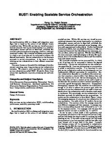
IEEE TRANSACTIONS ON NETWORK AND SERVICE MANAGEMENT, FALL 2009. 1. Service ... telecom services domain by introducing a common platform.
IEEE TRANSACTIONS ON NETWORK AND SERVICE MANAGEMENT, FALL 2009
1
Service Control Layer(SCL): Enabling Rule–based Control and Enrichment in Next–generation Telecom Service Delivery Nilanjan Banerjee∗ , Koustuv Dasgupta∗ , Lee Longmore‡ , Seema Nagar∗ , Sougata Mukherjea∗ , Li Na Ren† , Jia Jia Wen† , and Qi Yu† ∗ IBM Research, India Research Lab † IBM Research, China Research Lab ‡ IBM, Telecommunications Industry
Abstract—Telecom operators have started to make significant investments towards evolving their Service Delivery Platforms (SDPs) to a next-generation architecture, based on IP technologies and standards such as SIP, SOA and increasingly, Web 2.0. These investments are tightly coupled with demands for network middleware infrastructures that allow for rapid service creation and execution, efficient service orchestration and management, and flexible exposure of core network capabilities as services. A key service management functionality of integrated SDP is IP-based service control. Traditionally service control functionalities have been vertically integrated with service logic and hence are inflexible and costly to maintain and upgrade. IMS, which defines the overlay service architecture for next generation networks, stopped short in designing a flexible service control component. In this paper, we present the design and implementation of a flexible service control layer (SCL) for IMS networks, which is flexible on two fronts, viz., the SIP based service modeling for fine grained service control and the programmability of the controlling action implemented by external business services. We present the detailed description of the design and implementation of SCL followed by the results obtained from a performance evaluation excercise that evaluates the scalability of SCL. Keywords: Service Delivery, Service Control, IMS, Mashups, Web–2.0
I. I NTRODUCTION In the rapidly evolving Telecom landscape, convergence and increased competition have compelled traditional network operators to significantly overhaul their go-to-market strategies, as well as their enabling business processes, infrastructure and technology. With the saturation of voice revenues, carriers are aggressively looking to bring to market a new generation of communication services that boost customer adoption and revenue while minimizing costs. Business and consumers, on the other hand, want the ability to tap into information and communication services wherever and whenever they need them. They also want easy-to-use multimedia communication services that leverage rich, personal, and relevant content across networks, over the web, and using different device types. This requires a flexible platform that offers telecom services to a variety of users and business partners while providing dynamic control and management support for the offered services. Unfortunately, service enablers that support
rich communications such as presence, location, conferencing, and messaging are often trapped in silos of functionality within a carriers network. Consequently, subscriber services are delivered piecemeal, making them difficult to manage, enhance, or monetize. A concerted effort was made to clear up the imbroglio in telecom services domain by introducing a common platform called service delivery platform (SDP) 1 . SDP is an architectural solution that enables the re-use of service components trapped in “vertical service silos” by adopting a horizontal layered approach. There are capabilities beyond network enablers that need to be exposed through the operator’s SDP [16] - these include mobility, operations–billing support system (OSS– BSS) functions like billing and provisioning, subscriber profiles(like rich presence), QoS attributes of network elements, as well as profiles of devices supported by the operator’s network. SDPs are meant to be an innovation engine for operators by enabling faster, cheaper time to markets and service innovation independent of equipment vendors. The salient components of an SDP are service creation environment, service orchestration environment, service execution environment and service management environment. A number of standard bodies are working to come up with a reference architecture for SDP. Examples are Open Mobile Alliance Service Environment (OSE), TMF’s SDF, OSA Parlay, etc. Most of these reference designs expose the telecom capabilities through flexible SOA based programming interfaces such as Parlay-X [21]. Recently, telecom operators are exposing their capabilities through lightweight mashable interfaces or widgets to compete with the Web 2.0 Internet service providers. One such example is BT Web 21C [25] - a service aggregation environment that enables a user to create telecom mashup application very easily. The ease and flexibility of service creation and orchestration (composition) offered by the SDPs have resulted in a plethora of advanced value-added services developed and deployed in telecom networks. The management of these services is a very complex but a very critical operation for the success of any service provider. A key management functionality in converged networks is IP based service control that ensures many different services running over a single universal IP 1 http://en.wikipedia.org/wiki/Service
Delivery Platform
IEEE TRANSACTIONS ON NETWORK AND SERVICE MANAGEMENT, FALL 2009
Fig. 1.
Traditional IMS Service Delivery
network, while controlling the customer access by dynamically configuring and provisioning them in the run-time. Thus, service control requires knowledge of what occurs in the network and the ability to effectively manage it in a flexible customizable way. Considering the fast changing telecom services and application space, some desirable service control features are: 1) Swift adoption swiftly to market changes and customer preferences 2) Support of many different type of business models (e.g., changing the charging model of a service for a category of users) 3) Effective participation in a value network Today’s approach to IP-based service control is typically inflexible and costly to maintain. That is, service control requirements are hard-coded into service logic (IN, Session Initiation Protocol (SIP) Servlet etc.) during service development with limited configuration options. Where configuration is possible, it often requires highly specialized skills. The primitive service control in IMS based on SIP and SIP Application Servers also provides a fair degree of control to applications. While this method is widely used, we believe it is insufficient for the service delivery models that emerge out of a next-generation applications. Firstly, it often leads to a “one size fits all” model for service control which does not lend itself well to rapidly changing business and market requirements – especially in the case of mashup–based ecosystems. Further, current approaches tightly couple telecom services with backend IT applications such as CRM and billing, by means of hard-coding of service management policies and business logic into the application logic itself. In a mashup–driven ecosystem, this introduces downsides in third party service delivery models for both the operator and the third party. From the operator’s perspective, it might have to entrust service control - such as charging - to third parties for off-network services which may not always be desirable. From the third party’s perspective, it may have to adapt service logic to an operator’s environment which introduces complexity when seeking to partner with more than one operator. This is further illustrated in Figure 1, which shows that
2
today’s service logic is tightly integrated with sub-systems such as billing (1), adding complexity and redundancy to service logic. Further, some of the sub-systems are tightly integrated with other sub-systems (2) leading to ad–hoc and inefficient management of these services. In either case, this often leads to an static and costly one size fits all models. It is difficult, for example, to quickly change the way that services behave in response to a ever-changing business environment e.g. introduce variable charging schemes per user/user group, change business policies such as Service Level Agreements (SLA) - without resorting to costly and time-consuming code changes. In a Web 2.0–oriented ecosystem, it not only become a nightmare for operators to effectively partner with thirdparty services, but also make it infeasible to manage its own applications. To address this shortcoming we propose an IMS-based service control architecture for offering next generation telecom services. This service control architecture can be indeed incorporated into the larger scheme of things of an advanced next-generation SDP, but here, we keep that out of the scope of the paper. IP Multimedia Subsystem (IMS) defines an overlay service architecture that merges Internet services into Telecom service development. Figure 1 illustrates the IMS architecture that supports a wide range of services including traditional legacy services, i.e. Intelligent Network (IN) services, next generation IMS services with SIP [22] as the underlying protocol, and SOA-based Web Services. Introduced by 3GPP [1], IMS uses the SIP in the signaling plane to provide assistance and control for multimedia sessions, established between two communicating peers. Service control in IMS architecture is actually delegated to an entity called the Service Capability Interaction Manager (SCIM) [12]. The SCIM is envisioned to co-ordinate the diverse capabilities from different service domains, and orchestrate the interactions between them, using SIP as the control protocol in the signaling layer.2 The SCIM can loosely be likened to a SIP-based Application Server (AS) that performs the functionality of runtime orchestration of interactions between capabilities in the converged network. Such interactions can occur between SIP features and legacy signaling features (e.g. SS7), between components that are wholly implemented as SIP proxies or user agents [22], or even with external business capabilities that are exposed using Web services (WSDL, SOAP). Surprisingly, the 3GPP standard [2] only includes a loose definition3 of SCIM on its role of interaction management. The implementation of the SCIM has been left up to the vendors to suite their individual application requirements. As a result, the literature has very little on the design principles of a SCIM that one can refer to. Thus the SCIM with its limited scope of definition falls short in realizing the full potential of service control in IMS networks. 2 The reason behind the choice of SIP: Firstly, SIP is based on a simple request-response interaction model that allowsdevelopers to interact with individual protocol messages. Secondly, SIP can start/manage/tear-down sessions for any media type, be it voice, video, or application sharing. 3 An application server may contain “service capability interaction manager” (SCIM) functionality and other application servers. The SCIM functionality is an application which performs the role of interaction management.
IEEE TRANSACTIONS ON NETWORK AND SERVICE MANAGEMENT, FALL 2009
3
A. Contributions In this paper, we present a service control architecture to overcome the limitations in the IMS service architecture. Our major contributions are as follows. • We introduced a service control layer in the IMS plane to enable two flexible service control points. The first one is a rule based signaling protocol (SIP) level control point for native telecom services. This enables the flexible and easy modeling and monitoring of telecom services both by business and technical people. This brings in tremendous flexibility in terms of introducing new advanced telecom services and defining their tapping point for control activities. The second control point is implemented by a control enabling proxy that abstracts all the interactions between the service control layer and external business capabilities or services. These abstractions makes any change in the external capabilities transparent to the service control layer. We provide an easy way to configure this proxy, which makes the introduction of new external capabilities modular without any effect on the other components and interfaces of the service control layer. • We present the design of the SCL architecture and a detailed account of the implementation of a real-time charging control for a location based value added telecom service with SCL. • Finally we present a performance evaluation of the SCL with respect to a number of critical performance criteria. B. Organization of the paper: In Section II, we present a brief overview of IMS service and control architecture. Section III presents the design of SCL. In Section IV, we present the implementation details of SCL. Testbed setup for experiments has been described in Section V. Performance evaluation results for SCL are presented in Section VI. Section VII lists some of the important related works in this area of research. Section VIII concludes the paper. II. BACKGROUND : IMS S ERVICE A RCHITECTURE AND IT ’ S LIMITATIONS In this section, we provide a brief overview of the IMS architecture that is poised to form an integral part of the nextgeneration telecommunications platform for many network operators. We also highlight the rudimentary control of service provided by IMS to emphasize our contribution. The IMS reference architecture, shown in Figure 2, segregates the service, control and transport layers. IMS, however, does not deal with the transport directly, but provides a mechanism to converge networks based on a broad range of different wireless or fixed access technologies. The application developers have the flexibility to access and leverage the existing IMS services more easily through a Web services interface defined by Parlay-X. These include a number of services such as Third Party Call Control, Call Notification, Presence etc. Service control in IMS uses SIP as the protocol
Fig. 2.
IMS Service Architecture
and is realized by the co-ordination between SIP proxies in the signaling plane and the SIP Application Servers in the service plane. These entities are described as follows. SIP Proxies: The main elements in this signaling plane are the SIP proxies or servers known as the CSCF servers [1]. As shown in Figure 1, the service layer is completely decoupled from the control layer and the two interact via the ISC interface. This provides flexibility to new service logic without affecting the CSCF functions in the control layer. To interact with these proxies, the user devices must implement the functionality of a SIP user agent (SIP-UA). The CSCFs handle all the SIP session signaling, but neither take part nor are on the path of the application data. The IMS proxies are hierarchically divided in two categories [1]: (i) the Proxy-CSCFs (P-CSCFs) which are the IMS contact points for the SIPuser agents (SIPUAs) or end devices, (ii) the serving-CSCF (S-CSCF) which is the proxy server capable of controlling a session. We consider the latter for our remaining discussions. SIP AS: IMS defines a functional element called the Application Server (AS) in its service architecture to provide value-added functionalities. The AS represents capabilities or services, which are IMS components used presumably with other components (e.g., media servers) to implement a composite service for the user. Depending on the actual service, the AS can operate in SIP proxy mode, SIP UA (user agent) mode or SIP B2BUA (back-to-back user agent) mode [1]. The B2BUA mode is most relevant to our discussion since it is responsible for handling all SIP signaling between both ends of a session, e.g. from call establishment to termination, each call is tracked from beginning to end, allowing the operators of the B2BUA to offer more control and hence more sophisticated value-added features to the call. SIP Chaining: SIP is used as the IMS Service Control (ISC) interface used between the core network CSCF and service capabilities implemented in the SIP AS. Service invocation is done by a trigger mechanism. The Serving-CSCF (SCSCF) obtains the Initial Filter Criteria (IFC) from the HSS (Home Subscriber Server) for a registered subscriber. When
IEEE TRANSACTIONS ON NETWORK AND SERVICE MANAGEMENT, FALL 2009
Fig. 3.
4
Flexible rule-driven Service Delivery in SCL
the subscriber sends a SIP command, SIP INVITE for instance, for the multimedia session that one is requesting, the SCSCF cascades through the IFC and sends the invocation to the necessary Application Servers based on priority. While the S-CSCF has been enabled to invoke multiple sessions in a sequence, it is assumed that once the control is handed over to an Application Server, it will be the responsibility of the Application Server to coordinate with other services. Service orchestration in IMS, as explained here, is thus based on the concept of application chaining – in which, for the delivery of multiple applications for a single session, the session is routed sequentially between multiple application servers, acting typically as back-to-back user agents (B2BUA) or as SIP proxies. Thus, a chain of services is created, through which the session is passed allowing each application platform to perform its role in its turn. A. Limitations in IMS Service Control The primitive service control provided by the IFC in the CSCF server and the application chaining with SIP AS is fairly a rigid vertical because of the following reasons. The IFC can only match initial requests in a session like INVITE, REGISTER, SUBSCRIBE, MESSAGE etc. Subsequent messages (like BYE, NOTIFY, re-INVITE) are not checked and filtered by the IFC. This means that IFC alone is not adequate to model and monitor the entire life cycle of a service thus making it incapable of providing greater control to the services. Besides, changing the IFCs are not trivial, hence not flexible enough. The SIP AS chaining is also quite inflexible as the control logic developed in such a chaining application is not easy to change and the interaction with the external capabilities are often hardwired rendering them inflexible in the face of any change in the interaction with the external world. These inflexibilities make the primitive service control in IMS unfit for the next generation telecom service and application development. III. S ERVICE C ONTROL L AYER (SCL) In contrast to the traditional one-size-fits-all model of service control, SCL is a telecom middleware technology that employs an innovative decoupled approach to service delivery. SCL enriches traditional service control on two fronts, viz. (i) flexible, dynamic SIP service modeling and
Fig. 4.
SCL Architecture
(ii) transparent, flexible interface with external capabilities or business services. To begin with, SCL models a telecom service as a state machine (Figure 3). During the execution of a SIP service, SCL listens for exchange of service interactions (e.g. SIP INVITE) of interest between parties (applications and users) engaged in a service). Rules are then attached to state machines, typically for actions on state transition, such that they are triggered for evaluation on processing of a given protocol message. Each action is, in turn, mapped to a service-oriented capability that needs to be blended during service delivery. These actions invoke service oriented external business capabilities at runtime in order to control, enhance or personalise the service. The external capabilities are invoked through a configurable interface or Control Enabling Proxy (CEP). The CEP abstracts out the functionality of the external services and manages the interaction between SCL and the services transparently. A. System Architecture Figure 4 illustrates the system architecture of the SCL. The core components and their functionalities are described as follows. The Protocol Adaptation module handles different incoming protocol messages (e.g. SIP), and translates them into an internal format (known as Common Format Business Objects) for processing within the SCL. Additionally, it includes a SIP processor that inspects the SIP Initial Request (typically a SIP INVITE) and triggers one of the following modes for SCL to control a session: •
•
B2BUA Mode - Activates B2BUA mode for the SIP dialogue being processed, enabling the SCL to act as mediator between two SIP endpoints Terminating User Agent (TUA) Mode - Activates TUA mode for the SIP dialogue being processed, enabling the SCL to respond directly to the originator of the service session - for example, the SCL determines that a caller is not authorised to establish a service and sends SIP 4xx error in response to a SIP INVITE.
IEEE TRANSACTIONS ON NETWORK AND SERVICE MANAGEMENT, FALL 2009
Proxy Mode - Activates Proxy mode for the SIP dialogue being processed, causing all messages received to be proxied towards their intended destination following processing by the SCL. Objects are then routed to the Event Dispatcher. The Event Dispatcher is responsible for identifying services on receipt of events belonging to new service dialogues and for dispatching these events between SCL modules. State machines are used to monitor the execution lifecycle of a service, or at least those stages in the lifecycle that are significant to the control or enrichment of the service by the SCL. Generally speaking, a state machine is used to model the protocol messages of interest in a given service. Rules can be attached to state machines such that they are triggered for evaluation by a Rules Engine on receipt of a given protocol message. External data such as user profile information can be queried during rules evaluation. An orchestration mechanism that composes one or more “todo” items expressed in an execution sequence list is generated by the Rules Engine. The Control Sequence Processor (CSP) manages the invocation of external business services according to this execution sequence list. Business services (e.g. online charging)are exposed to the CSP through Control Enabling Proxies (CEP). The CEP is responsible for resolving the execution sequence list to the appropriate business capabilities, providing the required input parameters, as well as, processing the responses received back from the operation. •
B. How does it work? SIP protocol messages are routed to the SCL as they traverse the IMS control plane from source (e.g. a user’s mobile device) to the intended destination (e.g. another user or an application). On receipt of any message, SCL first determines whether a message belongs to an already active service session, or signifies the start of a new session. When new service session is established (e.g. SCL receives a SIP initial Request message such as INVITE), SCL identifies the type of service by applying pre-configured service identification rules to the message received. Based on this information, SCL creates an active instance of a pre-configured state machine to direct subsequent SCL processing activity throughout the lifecycle of the service session. 4 After service and party identification, or on receipt of a subsequent message belonging to an already active service session (e.g. a SIP ACK that acknowledges a session establishment), SCL forwards the message to the appropriate state machine. This will lead to a state transition in the active state machine. Pre-configured business rules may be executed during this transition to determine the service control required at this point in the service. Business rules are typically evaluated against data contained within the protocol message for example, examination of SIP Request URI - but may also utilise information from external data stores - for example, service and/or user profile information. 4 If the message is not relevant for service control requirement, it is simply forwarded to the destination.
5
Service control or enhancement at this stage can be achieved by: 1) The rules engine instructing an orchestration mechanism to call external business services; and/or 2) The rules engine instructing the SIP protocol adaptation module to change the service session from Proxy mode (default) [12] to either B2BUA [12] or TUA mode [12]. In scenario (1), the orchestration mechanism may call one or more external business services based on a “todo” list received from the rules engine - for example, authorise user then initiate session charge. The “to do” list may contain directives to allow list processing to be dynamically changed based on the responses received by the orchestration mechanism from a given business service - for example, only initiate session charge if the user is authorised to access the service. Responses from calls to business services may be directed back to the rules engine for further processing - for example, instruct the SIP protocol adaptor to terminate the service session if the user is unauthorised. Scenario (2) provides the SCL with the capability to control a service session either during session establishment (TUA mode) or during its lifecycle (B2BUA mode). In the TUA mode, the SCL is able to tear down a service session by responding directly to the originating party - for example, the SCL determines that a user has insufficient credit to establish a media session with another user. In the B2BUA mode, the SCL is able to “transform” a service session into a back-to-back session, effectively acting as a bridging point between service endpoints. This enables the SCL to exercise control over a service session at any stage during its life cycle. For example, the SCL determines that a user who is trying set up a VoIP session is on a pre-paid plan, and so instructs the SIP protocol adaptor to change the service session to B2BUA mode in case the user runs out of credit mid-session. If the user does exhaust her available credit and opts not to top-up, the SCL is able to generate a SIP BYE message towards all endpoints, effectively tearing down the session. The call to external business capabilities could be complex and a stateful one. Hence every time the behavior of the external service changes the interaction between the SCL orchestration mechanism and the external service needs to be remodelled and implemented all over again. This is an expensive proposition given the rapid changes expected in the external services due to enhancements and new features. In order to mitigate this problem we introduce a proxy functionality provided by CEP, between the SCL orchestration mechanism and the external services. A key function of CEP is to map actions (and paramaters, where specified) supplied by the Rules Engine to an appropriate interface (operation and arguments) supported by the target business service, including processing responses from the latter. A CEP can generate autonomous messages towards other SCL components e.g., a CEP communicating with a charging business service can inform the SCL after a stipulated time period that there is no credit left for a given user and that the SCL must therefore terminate the ongoing session. The introduction of CEP enables the decoupling of the external service interface with the
IEEE TRANSACTIONS ON NETWORK AND SERVICE MANAGEMENT, FALL 2009
SCL orchestration mechanism. The CEP can be configured for each individual external services, thus rendering flexibility in the interaction between SCL orchestration mechanism and the external services. The CEP consists of four major components as follows: 1) Interface to the SCL orchestration mechanism in CSP: This interface enables the CSP to send the directives to CEP required for leveraging the functionalities of external business services. 2) A state machine: It models all possible interactions with an external business service. There are as many state machines as there are external business services to interface with. 3) A timer module: The timer is internally managed with the CEP to trigger asynchronous events for both the SCL orchestration mechanism and the external services. 4) The proprietary interface with external business service: This interface hides all the details of the external service and exposes an abstract interface that accepts events from the CEP to trigger certain actions in the external service and send the response back to the CEP for further processing. C. How is it configured? The SCL has been designed to be configurable by users who undertake one of two distinct roles. These roles are loosely referred to that of a technical expert and that of a business expert. The former will typically be someone who is familiar with the protocol-level semantics of a service, while the latter will be concerned with implementing business policy and how a given service should be controlled or enhanced, e.g. for a particular user or group of users. The two roles provide an important distinction in the modeling of rules within the SCL. Some configurations are deemed to be design-time i.e. pertains to tailoring a service behavior and would require code to accommodate the same (e.g. integration of a new business capability like IPTV). This change would need to be facilitated by the technical expert, and would typically involve the use of design-time tooling. Other configurations could be deemed as being runtime. These changes could be achieved through simple configuration of business rules (which are consulted by the rules engine), and would typically be undertaken through an intuitive user-interface. The design of the SCL has been mindful of the distinction of the two roles, and wherever possible, has provided a layer of abstraction so that (multiple) business policies can be implemented flexibly and transparently from protocol-level details of a service implementation. The CEP is configured ideally by the external business service vendor who is knowledgable about all the possible state transitions that the service can go through. This is captured in the state machine in the CEP, which accepts input from the SCL facing interface and sends directives to the external service through the service specific interface. The timer module is also instantiated so that any asynchronous event can be fired or captured for possible state transition in the state machine.
6
IV. I MPLEMENTATION OF P ROOF - OF -C ONCEPT We now describe the implementation of SCL to demonstrate how it can apply flexible control and enrichment of a Telecom mashup service, using a combination of service modeling and rule-driven orchestration of SOA capabilities. A. Call-A-Cab Scenario The call-a-cab scenario is based on a mashup service called BusinessFinder [8], a next-generation, presence-enabled technology that leverages upon the underlying cellular infrastructure to provide efficient, on-demand, context-aware matching of customer requests to nomadic vendors. BusinessFinder mashes up location and presence information, along with call control features, exposed by a Telecom operator with third– party Google Maps service. Using BusinessFinder, one can search for a nearby and available vendor for a particular service. In the Call-A-Cab scenario, we consider Linda who is visiting Barcelona and wants to take a cab back to the airport. Using her GPRS–enabled phone, she logs on to the BusinessFinder portal and issues a search for a cab. Business Finder uses the location of Linda’s mobile phone to render a Google map showing all cabs which are available and within a few miles of her location, along with a star-rating for the cabs (Fig. 5(a)). Linda selects one of the cabbies, Chris, uses the Click-to-Call widget available as part of the mashup. This widget is enabled by IBM Telecom Web Services Server’s 3PCC (3rd Party Call Control) interface and initiates a SIP call between the devices of Linda and Chris. Now, let us see how the real-time charging operation can be done in a flexible way with SCL for the above scenario. Before the call is set-up the SIP INVITE is routed through SCL, which uses the service identifier (i.e. BusinessFinder) and the subscriber mobile number (i.e. of Linda) to issue real-time charging for this call. The charging model, in turn, would depend on the subscription plan of Linda (pre-paid, post-paid, premium etc.). Of particular interest is the scenario where Linda does not have an account with the operator. In this case, SCL pushes a SIP message to Linda’s device – the message includes an HTTP URI which Linda can visit to buy a “visitor pass” with some credits in it (Fig. 5(b)). Subsequently, SCL sets up a visitor account for Linda at runtime using the capabilities of the charging platform. Linda can now proceed to make the call and talk to the cabbie - to decide a time and location for the pickup. Once again, SCL (in a B2BUA mode) controls the entire call session and applies real-time charging to the call. Finally, when the call terminates (indicated by a SIP BYE), SCL pushes a second message to Linda’s device. The message includes an HTTP URI which Linda can visit to confirm her appointment with the cab driver. SCL charges Linda and the cab driver based on the charging policies of BusinessFinder. Finally, Business Finder updates Chris’s presence status to show that he is now busy picking up a passenger. Figure 6 demonstrates the key functional elements of the deployed architecture, namely (a) BusinessFinder - a Telecom mashup service, (b) SCL - for run-time control, mediation, and interaction management of 3PCC service that is invoked
IEEE TRANSACTIONS ON NETWORK AND SERVICE MANAGEMENT, FALL 2009
7
(a) Fig. 5.
Fig. 6.
(b)
(a) BusinessFinder Mashup, (b) Visitor Pass prompt to activate a visitor account at runtime.
Call-A-Cab: Integration Architecture Fig. 7.
as part of the mashup, (c) Openet [20] - the charging platform integrated with SCL and used to apply different charging policies to BusinessFinder users, and (d) Telecom Web Services Server [11] - an IBM Middleware SDP solution for delivering value-added Telco services like 3PCC. B. Service Modeling in SCL SCL uses Drools [10] to implement the Rules Engine. JBoss Drools is an open source and standards-based rules engine for easy business policy access, change, and management. What makes Drools an attractive choice for the SCL Rules Engine is a Declarative Programing style (allowing one to say ‘what to do’ rather than ‘how to do it’), along with almost natural language style semantics – making it suitable for the use of
Third part call control service - Call flow
Technical experts as well as Business analysts. The rules can then be mapped to executable (JAVA) code during compilation, and deployed on a live instance of SCL. Using Drools, we can model the interactions of a particular service as a state machine and further specify rules for service control (enrichment) at different points of its execution lifecycle. We elaborate on this with the help of the 3PCC service invoked as part of the BusinessFinder service. Figure 7 shows the SIP call flow for a 3PCC call setup between Linda and Chris’ devices. The 3PPCC service uses two SIP servlets to control the third party call based on a Back-to-Back User Agent (B2bUA) implementation. The first servlet handles the initial part of the call set up (i.e. messages 1–3). Once an ACK
IEEE TRANSACTIONS ON NETWORK AND SERVICE MANAGEMENT, FALL 2009
is received from the initial steps, the SIP control is passed to the second servlet which handles the rest of the call flow. Since the 3PCC call can be segmented into two different call legs, differentiated charging can be applied to the two different end users and is purely a business decision. For the sake of brevity, we consider the scenario where only Linda is charged for the service. In this case, SCL is interested in the call leg established between the 3PCC and Linda’s SIP terminal. The online charging needs to be weaved in such a manner that Linda needs to be redirected to a Visitor Pass page and create an account before proceeding to make the call. The message of interest to trigger the corresponding capability is an ACK from the 3PCC service to Linda’s terminal (message 3). If Linda has already activated an account, SCL needs to initiate real-time charging once Chris accepts the call, (i.e. ACK message 8 from 3PCC to Chris’ terminal), and terminate the charging once the session itself is terminated, (i.e. BYE message 12). The other messages (e.g. 180 Ringing, 200 OK) are not of interest to SCL, for this particular scenario. We use a combination of state machine and Future Processsing Directives (FPD) to model a telecom service. One of the merits of state machine is that it is well understood in telecom developer community. Telecom service providers have already successfully used state machine in many areas, for example, the protocol Specification and Description Language (SDL)5 . AT&T research also uses a state machine method for creating CallVantage Service6 . In contrast to the AT&T and SDL approach, the purpose of state machine in SCL is the selection of specific point in service. This method can be used to select only those messages that are of interest for the purposes of service management and control. As mentioned earlier, the messages which are of interest to SCL are the ACK from 3PCC to Linda’s terminal (message 3), ACK from 3PCC to Chris’ terminal (message 8), and the BYE (message 12) to Chris’ terminal. The other messages (e.g. 180 Ringing, 200 OK) are insignificant from the point of charging control. This fine-grained filtering out of insignificant messages is achieved in the SCL by a combination of state machine processing and FPD. As shown in Figure 8, FPDs can be set within each state or state transition in the state model to filter subsequent messages. On receipt of a subsequent message, FPDs can be applied to it to determine whether or not it should be filtered e.g., by examining message names using regular expressions, or by matching the message sequence number. Figure 9(a) illustrates a state machine with FPDs that could be implemented within the SCL for the charging control scenario described previously. When the state machine receives an INVITE message, the FPDs are set to enable ACK and CANCEL subsequent messages. When the ACK message is received, the FPDs are set to enable the BYE subsequent message. Messages other than these are filtered out by the SCL and immediately sent back to the network. By employing state machines and filtering directives to select necessary points of 5 ITU-T
(Recommendation Z.100)
6 https://www.callvantage.att.com/
8
Fig. 8.
FPD Modeling example
interest in service interaction, we essentially enable aspectoriented controls to the service. C. Configuring Business Rules in SCL A service like BusinessFinder offers numerous potential charging scenarios. For example, the service provider might wish to offer any or a combination of the following: (a) Subscription fees for BusinessFinder usage as a value-added service, (b) Transaction fees for the vendor (cabbie pays a dollar for every passenger he picks up), (c) Free to premium subscribers, vendor pays only, or (d) pay–per–usage for the requester along with applicable call charges. In an ideal world, one would expect different models being offered by the Telco for different subscribers and vendors. Consequently, any approach that includes charging logic as part of the application logic would be unmanageable, in terms of implementing flexible charging capabilities. Once again, the SCL Rules Engine enables charging rules to be configured in a flexible manner, outside of the application. Figure 9(b) illustrates the real-time charging that can be applied to Linda for making a 3PCC-enabled call to the cab driver. SCL, in a B2BUA mode, can transparently control the entire call session and invoke the necessary charging capabilities at different points of the session. As discussed previously, the action items specified in the rules can be mapped to external capabilities that are invoked by the CEP. D. Configuring the Control Enabling Proxy To illustrate the implementation of CEP in the context of the above use case, we describe how CEP realizes the interaction between the SCL and an external Online Charging System (OCS) from Openet [20] over Diamater [7]. The CEP can handle both types of requests, online charging as well as event based charging. But there is difference in the manner in which the requests are handled by CEP for the two cases. Online charging is a complex process; to model it efficiently a state machine is required, while for event based charging it is just a single transaction and hence a state machine is not required. Let us illustrate the operation of CEP for the online charging scenario. The CEP reduces the credit in a user account dynamically during time the session is active. It consists of three main operations, viz.: (i) reserveCharge: operation called when a service session is initiated, this operation is for the service to reserve some credit to reduce in subsequent
IEEE TRANSACTIONS ON NETWORK AND SERVICE MANAGEMENT, FALL 2009
Fig. 9.
9
Service Modeling and Rules Configuration
operations; (ii) onlineCharge: operation that reduces the credit every few seconds, and (iii) commitCharge: operation which adjusts the subscriber account once the call is terminated. In the case of a visitor (Linda), trying to place a 3PCC call, the CEP additionally implements a VisitorPass operation that enables Linda to dynamically create a visitor account with some credit in it. Note that, the number of credit units that need to be charged to a user depends on the charging policy (e.g. prepaid, postpaid, or visitor) and passed as parameters to the CEP operations. Finally, responses from the charging system are directed back to the SCL for further processing for example, instructing the SIP protocol adaptor to terminate the service session in a TUA mode, till Linda buys a visitor pass. As mentioned earlier, CEP consists of four components. They are implemented as follows: 1) Interface between CSP and CEP: This interface implemented using web services. Entry point to the CEP is, “invoke(SC_CF_Wrapper sc_cf_wrapper, ExecutionItem executionItem)”, where an operation name in executionItem tells the CEP what to do. When SCL requests “reserveCharge” operation which is starting of a new online charging session, invocation of “invoke” for this operation results in creation of a new state machine (described next) instance. And after creation of state
Fig. 10.
CEP State Machine
machine, the interface asks the state machine to do online charging for the session, pass the data needed (e.g username) as parameters to “reserveCharge” event and state machine in CEP initializes its data model from the event parameter and take the necessary action. Depending on the state on which the state machine is, the interface forms a response corresponding to the request from the SCL and sends its back to the SCL. 2) State Machine: State machine basically consist of two main components, first one is its data model which keeps all relevant information required by an online charging session
IEEE TRANSACTIONS ON NETWORK AND SERVICE MANAGEMENT, FALL 2009
10
Fig. 11.
CEP interactions when a user runs out of credit in the middle of a call
Fig. 12.
Code snippet showing the interaction of the CEP with the OCS
and the second one is its logic for online charging captured by state, event, transaction and onentry, onexit and ontransition actions. Figure 10 illustrates the online charging logic embedded in the state machine. It shows all the states, transitions and actions taken on entry or on exit or on transition by the state machine. For separate call sessions we have separate state machines in the system. Figure 11 shows the call flow for a scenario where user runs out of credit in the middle of a call. “ReserveCharge” request from SCL instantiates a new state machine as the CEP assumes this as a beginning of a new online charging session and fires the event “reservecharge” on the state machine. The state machine in turn transits to ‘‘PendingI’’ state and on entry of this state it makes web
service request to the OCS for CCInitial. A state machine instance is alive in the system as long as the call session is alive; removal of an instance from the system is done when the call session terminates, and this may happen because of the user runs out of credit or normal disconnection by the user. If CEP responds with success for “reserveCharge” request by SCL, SCL gets to know that the user have credits to make a call, then it acts in B2BUA mode and when the call is established it asks CEP to start online charge by sending another web service request with execution item operation set to “onlineCharge”. The online charging modeling requires CCUpdate from the charging server after the credits guaranteed earlier are consumed. For this purpose we have a timer associated with
IEEE TRANSACTIONS ON NETWORK AND SERVICE MANAGEMENT, FALL 2009
every state machine which, when credits get consumed, fires an event “TimerExpires”. State machine in turn sends out CCUpdate request to OCS and depending on the charging server’s response further action is taken. If response says, granted units are final units then we set “FinalUnits” flag to true and timer is scheduled. Before firing “TimerExpires” event, timer first checks whether “FinalUnit” flag is set or not. If not then it just fires event “TimerExpires” else it fires “commitCharge” event. If user hangs up before it runs out of credit, then in this case on receiving “BYE”, SCL sends out “commit charge” request to the CEP. CEP on receiving “commitCharge” request fires “commitCharge” event on the state machine, which in turn sends out “CCTermination” requestfollowed by a web service call to SCL to tear down the call and release the state machine instance. 3) Timer Module: As discussed above, in order to model online charging, state machine should get an event which says that the units which were granted have been used, so that it can send a request for new units. In our implementation, we have a “TriggerTimer” associated with every state machine. The “TriggerTimer” is responsible for firing the event “TimerExpires”. As shown in Figure 10 that this event results in transition from the state “Open” to the state “PendingU”. On entering the state PendingU an action is taken which sends CCUpate request to OCS. As the timer knows which units are final, it does not fire “TimerExpires” event for the final period, instead it fires commit charge. 4) Interface with OCS: This interface is implemented using the IBM IMS Connector [29] and uses the Diameter [7] protocol to communicate with the Openet Charging System. Besides the communication with OCS, it is also responsible for internal functionalities needed to form RO requests. Figure 12 shows the code snippet with one of such functionality, where a price enquiry request is sent to the diameter service, by constructing a RoChargingInfo wrapper initially, followed by sending a request containing the wrapper. V. E XPERIMENTAL T ESTBED In this section we describe the hardware and software configuration of an experimental testbed that we have used for evaluating the performance of SCL managing the charging scenario described above followed by experimental results. In particular, we have emulated the calls generated by the Calla-Cab application using a SIP workload generator and studied the scalability of SCL in the face of increasing call volumes. A. Server Softwares CSCF and SCL are developed as SIP Servlet applications for deployment over WebSphere Application Server Network Deployment 6.1 (WAS) [27]. CEP, implemented in Java, exploits Commons [28] SCXML technology to maintain the states representing various interactions with the OCS and uses Diameter Ro client provided by IMS Connector [29] to connect to OCS. The OCS functionality has been mocked up by inserting a constant delay in the path of end-to-end processing of SIP message as it was not our objective to study the behavior of any OCS in particular.
11
B. SIP Client Workload Generator We have used SIPp [26], a freely available open source software, as the workload generator tool. SIPp allows a wide range of SIP scenarios to be tested, such as user-agent clients (UAC), user-agent servers (UAS) and third-party call control (3PCC). There are two types of call flows described for 3PCC in RFC 3725. A basic one, where the two user teminals involved in the 3PCC call flow are identical to each other and the other, a more complicated one, where this condition is not necessarily true. Since, for our experiments the terminal capabilities are not important, we adopted the basic 3PCC call flow shown in Figure 7. For this, we had to change the service model in SCL as follows. There are four states in the state Machine which models the SIP session inside SCL, Idle, One_Party_is_Initialising, Call_Established and Call_Terminated. The state machine starts in Idle state, on receiving INVITE for party A, it makes transition to One_Party_is_Initialising state. The rule engine inside SCL has a rule that sends request to OCS for reserve charge as follows: Rule: Reserve VoIP Fee (Subscriber) if Current state is “One Party is Initialising” then Store subscriber and vendor address Trigger action “reserveCharge” with parameters of service name “BusinessFinder” Reserve unit “300” user “SUBSCRIBER” end if Next, on receiving ACK, if previous state is One_Party_is_Initialising then state machine makes transition to Call_Estabalished state and in turn rule engine invokes the following rule which starts online charging. Rule: Trigger VoIP Session Charge (Subscriber) if Current state is “Call Established” then Trigger action “startCharge” with parameters of service name “BusinessFinder” end if Finally, on receving BYE message, if previous state is Call_Estbalished then the state machine makes transition to CALL_TERMINATED state and the rule engine invokes the rule for commit charge.
C. System Configuration All the server software components have been deployed on a 2 Ghz Intel X86-based PC, with a Dual Core Processor (x86 Family 6 Model 14 Stepping 8) and 2 GB of physical memory, running Microsoft Windows XP Professional Version 5.1.2600 Service Pack 2 Build 2600. The server machine is equipped with an Intel(R) PRO/1000 PL Network Connection network interface. SIPp v3.1-TLSPCAP clients have been deployed on a separate Linux PC to generate the workload remotely over an enterprise LAN.
IEEE TRANSACTIONS ON NETWORK AND SERVICE MANAGEMENT, FALL 2009
12
appropiate response following an appropriate action. VI. R ESULTS We report the results of our experimental studies based on the parameters described above. A series of experiments have been carried out for increasing call load (λ), in terms of calls per minute, offered to the system. Each run of experiment was carried out for 1100 calls generated by the SIPp 3PCC service and the latency and the throughput parameters were measured. The calls were generated following a uniform distribution, which in turn depended on λ, while the duration of the calls followed normal distribtion where the mean (µ) was varied between 15, 30, and 60 sec. Fig. 13.
Basic 3pcc Call Flow
A. Latency Measurements D. Experiments and Metrics For our scalability measurements we primarily measure throughput and latency as a function of the load on SCL in terms of calls per minute. Throughput has been measured using various call statistics available from SIPp logs, in particular, with respect to the following three parameters. • Successful calls: This parameter represents the number of calls successfully processed by SCL and got terminated as expected following a termination request in the form of a SIP BYE. • Unsuccessful calls: This parameter represents the number of failed calls due to various types of exceptional conditions that may occur with increasing load on the system. The number of unsuccessful calls again can be classified under two categories, viz., blocked calls and dropped calls. Calls which are initiated but not established are classified as blocked calls and calls which are established but terminated exceptionally due to some reason are termed as dropped calls. • Peak Calls: The number of peak calls represents the maximum number of ongoing calls in the system at any point of time within the experimental timeframe. We define latency as the time taken by SCL to process the SIP messages and take appropriate action during the lifecycle of a call. Latency is a measure of system responsiveness, which is very critical for systems with real-time requirements such as SCL handling voice calls signaling with stringent QoS requirements. For example, E.721 [30] recommends an average call setup delay of no more than 3, 5 or 8 sec, for local, toll and international voice calls, respectively. So, if the latency in processing any of the SIP message involved in call setup is greater than this stipulated limit of the end-to-end call setup delay then the performance of SCL should be considered unacceptable. To minimize the experimental perturbation and variability in the end-to-end latency measurement that may occur in the enterprise network, we considered only the time taken by SCL to process the SIP messages and take appropriate actions in our latency measurements. Formally, we measure latency as the time difference between the instant a SIP message (INVITE, ACK, BYE) reaches the SCL and the instant at the which the CEP returns to the SCL with an
Latency, as we have defined earlier, is the time taken by the SCL to process the SIP messages followed by CEP taking the appropriate actions. We have chosen to measure the median of the latencies measured for 1100 calls over the mean, as median is a more appropriate index for datasets with variable cardinality and here we have considered only the variable number of successful calls (which, as we shall see shortly decreases with the increasing load on the system) for latency measurements. Figure 14 shows the latency measurements of INVITE, ACK and BYE messages against increasing λ, for different values of µ. We observe from the results that the gradient of increase of the latency increases with λ. The reason is with increasing λ there are more calls in the system on an average and overloads the system faster. That the increasing latency is due to system overloading is further corroborated later with the throughtput statistics where we will see that more calls are rendered unsuccessful with the increasing call duration. The curve showing the additional call setup delay in the plots indicate the delay introduced by the processing of SIP messages in SCL during the call setup process. It has been observed that this additional call setup delay for λ = 30 calls per minute is 1.015s, 1.312s, and 1.797s for mu = 15s, 30s, and 60s, respectively. For higher λ, the additonal call setup delay is more than 3 s, which, as mentioned before, is greater than the stipulated limit for the maximum call setup delay. Hence, in terms of latency we can infer that under the current system constraints, the maximum allowable call rate is 30 calls per minute, which can be of course increased by employing more powerful computing infrastructure. Another interesting observation from the results is that processing of ACK takes the least time when compared to INVITE and BYE. One reason behind this observation is that while INVITE and BYE involve either creation or deletion of call or dialog state machines within the SIP stack and state machines in CEP, ACK does not get involved in the creation or deletion of the state machines. B. Throughput Measurement We present here the throughput measurements in terms of the three parameters.
IEEE TRANSACTIONS ON NETWORK AND SERVICE MANAGEMENT, FALL 2009
13
Successful calls with increasing call rates
Mean Call Duration = 15s Mean Call Duration = 30s Mean Call Duration = 60s
1000
Median Latency with increasing call rate
800
30000 Number of successful calls
INVITE ACK BYE Additional Call Setup Delay 25000
Latency (msecs)
20000
15000
600
400
200
10000
0 10
20
30
40
50
60
70
Calls per minute
5000
Fig. 15.
Successful calls vs. call rate (λ)
0 10
20
30
40
50
60
70
Calls per minute
(a) Latency vs. Call Rate (λ) for µ = 15s
1) Successful Calls: Figure 15 shows the number of successful calls with inreasing λ for different µs. It is observed that the current experimental setup is good for handling 40 calls per minute and that too decreases with the increase of µ. Thus for µ = 60s calls start getting blocked or dropped after 30 calls per minute.
Median Latency with increasing call rate
30000 INVITE ACK BYE Additional Call Setup Delay 25000
Latency (msecs)
20000
15000
10000
5000
0 10
20
30
40
50
60
70
Calls per minute
(b) Latency vs. Call Rate (λ) for µ = 30s Median Latency with increasing call rate
30000 INVITE ACK BYE Additional Call Setup Delay 25000
Latency (msecs)
20000
15000
10000
5000
2) Unsuccessful Calls: Figure 16 shows the breakup of unsuccessful calls in terms of blocked calls and dropped call as defined above. In general, for different µ, while the number of blocked calls increases with λ, the number of dropped calls also decreases. This is because with the increase in λ the system gets overloaded and starts dropping calls. Without proper admission control mechanism in place, the incoming calls get admitted even when the system is overloaded and drops calls. But after sometime, the system losses the capability of even accepting the INVITE due to excessive load at higher call rates and starts blocking calls as well. Hence, the number of blocking calls increases progressively. This somewhat checks the offered load to the system and with time some calls also terminates naturally thus releasing some of the resources which the system can utilize further to process the remaining of the ongoing calls - hence, the number of dropped calls reduces gradually. The knee of the curves in each plot indicate the point at which the system starts drastically dropping and blocking calls. The knee points in these plots also corroborates the results shown in Figure 15 showing the number of successful calls. Another observation is that the knee points shift more towards lower call rates with increasing µ because of the increase in the effective load on the system with increasing µ.
0 10
20
30
40
50
Calls per minute
(c) Latency vs. Call rate (λ) for µ = 60s Fig. 14.
Median latencies vs. λ for different µ
60
70
3) Peak Calls: Number of peak calls, as defined earlier, gives an estimate of the effective load offered to the system at that point of time. It gives the measure of computational resource that the system is spending for processing ongoing calls. Figure 17 shows the number of peak calls in the system with increasing λ for three different values of µ. As observed previously, the system gets overloaded at 40 calls per minute for µ = 15, 30s and it is 30 calls per minute for µ = 60s.
IEEE TRANSACTIONS ON NETWORK AND SERVICE MANAGEMENT, FALL 2009
14
Peak calls with increasing call rate
800 Mean Call Duration = 15s Mean Call Duration = 30s Mean Call Duration = 60s
700
600
Unsuccessful call breakup for mean call duration = 15s
1400 Unsuccessful Calls Dropped Calls Blocked Calls
Number of calls
500
1200
Number of calls
1000
400
300
800
200
600
100
0
400
10
20
30
40
50
60
70
Calls per minute
200
Fig. 17.
Peak calls vs. call rate
0 10
20
30
40
50
60
70
Calls per minute
C. Discussion
(a) µ = 15s
From the above results it is evident that, under the constraints of the current setup, it is possible to support a maximum λ of 30 calls per minute with satisfactory QoS even for calls with longer durations. Beyond this threshold call rate, even though a large percentage of calls are processed without exceptions, it has to be noted that the delay also starts shooting up beyond the threshold point and results in unsatisfactory QoS.
Unsuccessful call breakup for mean call duration = 30s
1400 Unsuccessful Calls Dropped Calls Blocked Calls 1200
Number of calls
1000
800
600
VII. R ELATED W ORK
400
200
0 10
20
30
40
50
60
70
Calls per minute
(b) µ = 30s Unsuccessful call breakup for mean call duration = 60s
1400 Unsuccessful Calls Dropped Calls Blocked Calls 1200
Number of calls
1000
800
600
400
200
0 10
20
30
40 Calls per minute
(c) µ = 60s Fig. 16.
Unsuccessful calls vs. call rate
50
60
70
IP service control is an active area of research in network service management. Some of the early works [31, 32] in IP service control were targeted for legacy networks, mostly in an ad hoc manner. Later, IP based service control was somewhat formalized [33] for next generation networks by standard bodies such as 3GPP, resulting in overlay service control frameworks (viz. IMS) for delivering advanced services. Service control in IMS, however, is very rudimentary and much of the flexibility in service control has been delegated to a fuzzy architectural component viz. SCIM, which has been left to the vendors for design and implementation. Stray attempts have been made to realize the SCIM functionalities and beyond. For example, JSR 289 [15], that is aimed at enhancing the capabilities of JSR 116 [14] SIP Servlet specification, is a step in the direction of standardizing the orchestration capabilities of SCIM in a converged WebTelecom service layer. A key agenda of JSR 289 is to make HTTP (SOAP)–based services available on the same platform with SIP–based services. An early SCIM implementation [9], based on the specifications, has also surfaced recently. Once again, this proposal fails to address the flexible control requirements imposed by blended services. With the emergence of Web 2.0 and a large number of shortlived services in this paradigm, the requirement of flexible service control has become even more critical. A number of vendors have started offering service development and deployment platforms in this space. Examples are, BEA’s
IEEE TRANSACTIONS ON NETWORK AND SERVICE MANAGEMENT, FALL 2009
Aqualogic [5], British Telecom’s Web21C [25], and Microsoft’s Connected Services Framework Sandbox [18]. The key feature of all these offerings is the exposure of Telecom services as lightweight widgets, which are easy to incorporate in a mashup environment. However, none of these consider runtime control and mediation of the mashup services. To bridge this gap, a layered architecture is proposed in [4] for executing Telecom mashups in a Web 2.0–oriented domain. The authors suggest the need of a service co–ordinator for runtime mediation between the Web and Telecom capabilities that are blended as part of the mashup, but no concrete solution was presented. In this paper, we have built on this service co-ordinator concept and designed SCL to provide flexible service control, both in terms of telecom service modeling and programmable interface with external business services. To the best of our knowledge, such flexible service control has not been reported earlier. Interestingly, as an aside, SCL’s approach of rule–driven control can be likened to an aspect– oriented programming paradigm [23], where each service control requirement is modeled as an aspect of concern. This approach allows telecom operators to selectively apply service controls at different points throughout a service execution lifecycle, outside of the service logic itself. As discussed earlier, dynamic service control requires blending of services in the runtime. Hence, it can be loosely linked to the body of work on service composition, although the latter typically deals with the static paradigm primarily. Service composition and orchestration have been extensively studied in the realm of Web services. The topic is less studied in the context of service blending in a converged Web– Telecom services layer. It is only with the emergence of mashups, and the willingness of operators to open–up some of their core enablers, that the topic has become particularly relevant. A number of research efforts [3, 17, 19] have addressed the problem of service creation (or composition) in Telecom services – where Telecom enablers are exposed as Web Services (e.g. using Parlay–X). The solutions address how to combine existing services to provide a value–added functionality. None of them, however, consider the problem of service control and the challenges that arise from it. An alternative service composition framework based on JAIN SLEE [13] architecture has been presented in [24]. This work highlights benefits and drawbacks of Web service applications within a telecom environment and suggests run–time support for telecom service development. The drawback of the approach is that the solution requires run–time logic to be configured as part of the application logic, thereby, losing out on the desired flexibility. Further, the solution is pinned down to the particular technology of JAIN SLEE. Competing middleware vendors [6, 11] have recently rolled out a number of products in a bid to simplify telecom service creation and enable fast–and–easy development of value– added services. However, all of these offerings deal with Telco service interfaces and do not provide “hooks” to enable run– time control or customization of the services.
15
VIII. C ONCLUSIONS A ND F UTURE W ORK In this paper, we present the Service Control Layer (SCL) – an innovative Telecom middleware technology for enabling operators to quickly and flexibly control, enrich and personalise the delivery of converged services through an IMSenabled, SOA-based service delivery platform. SCL aims to fill a technology gap in the architecture of current SDPs in terms of applying transparent and fine–grained service– control requirements to next–generation service delivery. Such requirements are particularly important for operators to survive and succeed in the rapidly evolving ecosystem of mashups. To date, the focus of our work has been on processing SIP messages to apply service control. However, in a Web–2.0 domain, SCL might additionally need to process non–SIP (e.g. SOAP) messages generated from a user–driven session. Accordingly, as a part of our ongoing efforts, we plan to extend SCL to model such interactions and apply rule–driven blending of Web/Telecom capabilities. Finally, we plan to investigate the role of SCL in enriching a range of service delivery scenarios, e.g. rich media sessions of a peer-to-peer nature that might otherwise be beyond the control of the service provider. R EFERENCES [1] 3rd Generation Partnership Project: http://www.3gpp.org [2] 3rd Generation Partnership Project; Technical Specification Group Services and Systems Aspects; Network architecture (Release 6), 3GPP TS 23.002 V6.10.0, 2005. [3] V. Agarwal, K. Dasgupta, N. Karnik, A. Kumar, A. Kundu, S. Mittal, and B. Srivastava, “A Service Creation Environment based on End to End Composition of Web Services,” Proc. of 14th International World Wide Conference, 2005. [4] N. Banerjee, K. Dasgupta and S. Mukherjea, “Providing Middleware Support for the Control and Co-ordination of Telecom Mashups,” Proc. of MNCNA: Middleware for Next-generation Converged Networks and Applications, 2007 [5] BEA AquaLogic Family of Tools. www.bea.com/aqualogic/ [6] BEA WebLogic Network Gatekeeper. www.bea.com/content/news_events/white_papers/ BEA_NW_Gatekeeper_ds.pdf [7] P. Calhoun, et. al., “Diameter Base Protocol,” RFC 3588, September 2003. [8] D. Chakraborty, K. Dasgupta, S. Mittal, A. Misra, A. Gupta, E. Newmark, C. L. Oberle, “BusinessFinder: Harnessing Presence to enable Live Yellow Pages for Small, Medium and Micro Mobile Businesses”, In IEEE Communications Magazine, Special Issue on New Directions In Networking Technologies In Emerging Economies, January 2007. [9] T. Dinsing, G. AP Eriksson, I. Fikouras, K. Gronowski, R. Levenshteyn, P. Pettersson and P. Wiss, “Service composition in IMS using Java EE SIP servlet containers,” Ericsson Review, Number 3, 2007. [10] Drools, http://labs.jboss.com/drools/ [11] IBM WebSphere Telecom Web Services Server, http://www-306.ibm.com/software/pervasive/serviceserver/ [12] IP Multimedia Subsystem (IMS); Stage 2, Release 8, 3GPP Specification TS 23.228, 2008. [13] JAIN SLEE, http://jainslee.org/ [14] JSR 116: SIP Servlet API, http://jcp.org/en/jsr/detail?id=116 [15] JSR 289: SIP Servlet v1.1, http://jcp.org/en/jsr/detail?id=289 [16] “Telco Web 2.0 Mashup: A New Blueprint for Service Creation,” Lightreading’s Services Software, Volume 3, Number 2, May 2007. [17] S. Majithia, M. Shields, I. Taylor, and I. Wang, “Triana: a Graphical Web Service Composition and Execution Toolkit,” Proc. of IEEE International Conference on Web Services, 2004. [18] Microsoft Connected Services Framework Sandbox http://www.microsoft.com/serviceproviders/solutions/ connectedservicesframework.mspx [19] S. Mittal, D. Chakraborty, S. Goyal, S. Mukherjea, “SewNet - A Framework for Creating Services Utilizing Telecom Functionality”, Proc. of 17th International World Wide Web Conference, 2008. [20] OPENET, http://www.openet.com/
IEEE TRANSACTIONS ON NETWORK AND SERVICE MANAGEMENT, FALL 2009
[21] Parlay X Web Service Specification, Version 3.0, http://portal.etsi.org/docbox/TISPAN/Open/OSA/ ParlayX30.html [22] J. Rosenberg, et. al., “SIP: Session Initiation Protocol,” RFC 3261, June 2002. [23] P. L. Tarr, H. Ossher, W. H. Harrison and S. M. Sutton Jr., “N Degrees of Separation, Multi-Dimensional Separation of Concerns”, Proc. of International Conference on Software Engineering, 1999. [24] C. Venezia and P. Falcarin, “Communication Web Services Composition and Integration”, Proc. of IEEE International Conference on Web Services (ICWS), 2006. [25] Web 21c sdk. http://web21c.bt.com/. [26] R. Gayraud and O. Jacques. SIPp. http://sipp.sourceforge.net [27] WebSphere Application Server Network Deployment 6.1, http://www-01.ibm.com/software/webservers/appserv/ was/network/ [28] Apache Commons, http://commons.apache.org/scxml/ [29] WebSphere IP Multimedia Subsystem Connector , http://www-01.ibm.com/software/pervasive/multisubcon/ [30] International Telecommunication Union, Network grade of service parameters and target values for circuit-switched services in the evolving isdn, Recommendation E.721, Telecommunication Standardization Sector of ITU, Geneva, Switzerland, May 1999. [31] M. Kakemizu, M. Wakamoto, A. Orita, Unified IP Service Control Architecture Based on Mobile Communication Scheme, FUJITSU Sci. Tech. J. 37, 1, Page(s): 81-86, 2001 [32] P. Trimintzios, et. al., A Management and Control Architecture for Providing IP Differentiated Services in MPLS-Based Networks, IEEE Communication Magazine, Page(s): 80-88, May 2001. [33] M. L. F. Grech, M. Torabi, M. R. Unmehopa, ”Service control architecture in the UMTS IP multimedia core network subsystem”, Third International Conference on 3G Mobile Communication Technologies, Page(s): 22-26, 2002.
16