Service Oriented Architecture Implementation Model for Enterprise Collaboration Rim Hur*†, Hyunsang Youn*, Eunseok Lee* *
School of Information and Communication Engineering Sungkyunkwan University, Suwon, 440-746, Korea Tel: +82-31-290-7220, E-mail: {wizehack, eslee}@ece.skku.ac.kr † System Engineering Team, Semiconductor Business Samsung Electronics Co., Yongin, 446-711, Korea Tel: +82-31-209-3938, E-mail:
[email protected]
Abstract— Since the computer era began, companies built various information systems in order to increase efficiency and fulfill the customer requirement. While the number of systems doubled, the number of interfaces linking the systems increased and the interface type became various. Accordingly, the management of interface became a big challenge. This paper suggests SOA as system interface and a step-by-step implementation model of SOA. In addition, a prototype of executing the model is shown for detail explanation. The prototype demonstrates how SOA could increase user convenience.
I.
The first step describes how to use SOA as the unified interface between different platforms. The next step model merges many system functions into a single view for the user to work. In the last step, users define their own business process and connect the service, so an application can be developed at the business-oriented development. The stepwise model will be particularly helpful for the developer who does not have any experience to develop a system with SOA. We classify services to divide the services into groups so that the user could or could not select the services. The services that can not be selected are system level. So users just organize a workflow that processes user’s tasks and select services that model work for each task. This paper proved the impact of SOA by implementing SOA prototype at a sample process. The rest of the paper is organized as follows: In Section 2, we outline a brief overview of SOA and the method to implement SOA on .Net Framework. Section 3 describes the status of interfaces existing on Company S. Step-by-Step models are proposed in Section 4. Section 5 shows how we implement a prototype. In Section 6, we experiment the access route before and after the prototype. Finally Section 7 gives an outlook to remaining issues, challenges and future work.
INTRODUCTION
Since the introduction of service oriented architecture (SOA) at 1996 by Gartner Group, SOA has been one of the major topics about system integration because SOA is regarded as the most optimized development method which could response quickly at system change and environment change. Every system becomes unique when the performance is optimized according to the different business environment. On the other hand, a system has to exchange data with different systems in order to provide consolidated data required by the management. Various interfaces are used to setup the data exchange. Standardizing these different interfaces is important for efficient IT management; however, stability and security requirement hinders standardization. SOA is thought to be the key to this problem. In addition, many companies are trying to implement SOA so that they could response quickly and gain flexibility to survive in the rapidly changing business environment. Company S also considered using SOA for the same reason but the fact that the stability of SOA is not proven by the market blocked the company from executing the idea. The impact of SOA has been widely researched but there is no standard about how to implement SOA. It troubles that having no proven model when developers try to implement SOA. For example, standardizing communication protocol is a big issue. This paper suggests a model which could consolidate system interface and a step-by-step model for SOA implementation.
978-1-4244-4522-6/09/$25.00 ©2009 IEEE
II.
RELATED RESEARCHES
A. SOA Overview The purpose of SOA is to reuse service, a bundle of software components which execute business process. The service contains meaningful business functions. SOA is a collection of service which could communicate with other systems.[1][2]. The characteristics of SOA are 1) that SOA is flexible because the services are tied loosely – one application does not need to know the technical specification of the other application in order to use the service - 2) that SOA is independent from technology and platform 3) that service, which could be a defined by business function, could be reused.[2]
495
ISCIT 2009
Although a developer does not know about the technical details, the developer can create a new application using services from a distributed application network. The effort could be focused on business process. High level application development method, called coarse granularity, hides the low-level technical complexity by using standard interface and focus on business application. In other words, application for new business requirement could be easily created using existing services.[2] Web service is not necessary to implement SOA but most suitable method to implement. Web service uses XML based simple object access protocol (SOAP) to exchange messages with web services description language (WSDL) to broadcast the service contents. Occasionally, universal description, discovery and Integration (UDDI) is used to broadcast service contents and location.
Fig. 2.
III. INTERFACE BETWEEN EXISTING APPLICATIONS
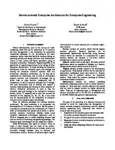
B. SOA on .Net Framework In order to implement SOA on a legacy Windows system, Windows Communication Foundation (WCF) from Windows .Net Framework was selected. WCF manages the communication between applications on .Net 3.0 Stack.
Fig. 1.
Two type of interfaces in WCF a) between Windows applications b) between Web applications
SOA could be used as Enterprise Service Bus (ESB) for interface integration. As shown below in the table 1, Company S has been building lots of connection using different technology. The table shows the interface of the four major information system, R&D, sales, customer, and production system. We sorted the interface into 6 categories: 1) DB link, 2) FTP, 3) RFC (Remote Function Call), 4) EAI (Enterprise Application Integration), 5) ETL (Extract, Transform and load), 6) others. Few systems are partially standardized upon implementing EAI and ETL. However, we decide to integrate the interface by SOA because data standardization project is running and the result of this project will help the integration. Recently, most EAI or ETL supports SOA. In other words, EAI or ETL could be used for SOA.
WCF in .Net Framework 3.0 [3]
WCF provides a framework for system interface. WCF could be used for 2 types of communication 1) communication between Windows application 2) communication between web applications based on SOA.[4] The figure below shows an example. At figure 2-a), the client application uses proxy code such as CORBA’s stub. Client application implements execution code using the proxy code. At Figure 2-b), client application just uses WSDL. Only SOAP messages are being exchanged between the web services. For application integration of Company S, the method of figure 2-b) was used to develop the service of the PLM system. For application integration, we developed PLM functions into SOA type services, using 2-B) type interface.[4] Once the service is implemented, WCF supports three types of hosting. 1) Registering Microsoft IIS 2) registering as a windows service 3) using an independent hosting application. For the project, we decided to use the last method 3).[4] For availability, monitoring the services is necessary. If the service becomes poor, the provider should be warned that the service is no longer available. Therefore, we choose independent hosting application to monitor the services.
TABLE I INTERFACE STATUS OF THE ESSENTIAL SYSTEMS OF THE COMPANY S (): Interface integration targets Custome Manufact Sum r ure 446(375) 0 337(332) (46.1%) 81(81) 0 81(81) (8.4%)
Type
R&D
Sales
DB Link
109(43)
0
FTP
0
0
RFC
6
0
0
18
24(2.5%)
EAI
0
0
235(10)
0
235(24.3%)
ETL
0
180(40)
0
0
180(18.6%)
Etc.
1
0
0
0
1(0%)
Sum
116(43)
180(40)
235(10)
436(413)
967(506)
We recorded daily interface number of each system on a week of November, 2008. Company S has 967 interfaces; among them, 506 interfaces are not standardized. Average number of communication is over 11,000 times per day for each system.
496
the system manually, a situation which causes delay and potential mistake. To solve the past problems we have to: 1) survey all interfaces to be changed, 2) estimate the effect of changing, 3) let all systems to support web services by direct or indirect methods, 4) get resources for systems to be changed.
TABLE II THE NUMBER OF DAILY INTERFACES OF THE COMPANY S’S ESSENTIAL SYSTEMS
1st
The number of the interfaces 11,297
2nd
11,297
IV. STEP-BY-STEP SOA IMPLEMENTATION MODEL
rd
3
11,303
4th
11,297
5th
11,382
6th
11,513
As shown in the previous chapter, Company S uses many interfaces with different technology. It is possible to standardize the interface using universal support of SOA. Moreover, latest EAI or ETL solutions help SOA implementation. If the platform does not allow implementation, SOA could be operated through developing web service environment or use an adapter for web service. Many vendors and platforms provide development tools for SOA. Therefore, we choose to integrate interface by using SOA as ESB. After the interface integration, we will add on core service of SOA, which provides business-oriented application capability. Changing the platform of a 24-hour working system has to be careful. Especially, when the documentation is not maintained, a developer should be careful. Therefore, we will implement SOA step-by-step.
Survey Day
7
th
Avg.
11,297 11,355
Data exchange is inevitably high for such a large company like Company S. For example, after the design of a chip is finished, a mask for production has to be made. For this process, data should be exchange among various systems for procurement, billing, status check, and so on. One business process is distributed over many information systems. However, every function that each system manages is meaningful. Security is very important when interfacing blueprints of chip. Figure 2 shows an example of system interface of mask data. Related systems are 1) CAE system which converts the design to a pattern 2) PLM system 3) document management system 4) procurement system 5) mask production system of outsourcing companies 6) production system of Company S. The main roles of the systems are depicted in Figure 3.
Fig. 3.
The system collaboration in the mask making process in the company S
Currently, like many other company, Company S interfaces are connected in the form of mash topology, using various technologies for each connection. This causes many problems such as 1) data integrity and time delay because of multi-layered interface 2) master data error between batch and real-time data is poorly managed 3) in case of using DB link, the impact of changing the source data is not measurable 4) the large number of interfaces using different technology make it difficult to manage data and interface 5) when error occurs during a scheduled job, engineers recover
Fig. 4.
Stepwise SOA implementation model in the company S a) step 1 – interface integration with the monitoring system b) step 2 – application implementation on a single view portal using the services c) step 3 – service orchestration by BPM
497
Fig. 4-a) shows the step 1 integrating web services using ESB. A few systems are using EAI or ETL to integrate interface. However, the interfaces of others systems, such as small systems, stable systems, or frequently changing system, were not integrated. At step1, the increased number of interface caused increased amount of management effort. To efficiently manage such increasing interface, we will try to integrate the interfaces. Besides, monitoring system will be setup to prevent unfortunate accidents. Fig. 4-b) illustrates the step 2 as the single view portal using services by SOA. Currently, a user had to connect many different systems for different steps of the business. For user convenience, we tried to build a consolidated view portal where users could work with a single logon. Fig. 4-c) is the end of the stepwise models for adapting SOA to the enterprise through BPM.[5] Service orchestration, an activity of collecting the functions to build a service for business process in SOA, was done through business process modeling and through this we tried to approach to the service in the aspect of business process. By these stepwise models we will process gradual improvement. The step-by-step approach will make us to: 1) achieve a centralized management of interfaces, 2) estimate the effect to all the destination system by origin management, 3) make a detour to implement the SOA by EAI, ETL adapters who cannot support Web services well, 4) focus the interfaces need to be changed. In addition we divide the web services into user services or system services to expose only services for user tasks. We classify the user services into Request or View by the necessity the feedback of systems or users. Through this, application development is possible at the user perspective, in other words business viewpoint.
V.
TABLE III THE SERVICE REQUIREMENT LISTS FOR THE PROTOTYPE *: included by other service ID S001 S002 S003 S004 * S005
S006 S007
S008
S009 S010 * S011 * S012 * S013 * S014 *
IMPLEMENTATION
We developed a prototype to how to implement the stepby-step model. Most of the PLM functions were transformed into services using .Net based WCF mainly. The rest of the required services are built using web services. Systems which are interfacing through EAI or ETL are providing services based on the functionality of EAI or ETL. This target of the project is to create a new application which executes the part of the mask production project mentioned before. We extracted the required service for the process as shown in table 3. In addition, we limited the project scope, number of target systems, resource, and quality so that the customer could see the demonstration as soon as possible. Other considerations, such as security, authorization, standardization registration, were not considered. The PLM system manages project tasks, which is managed by the WBS (Work Breakdown Structure). The system also provides request forms, approval system and schedule management functionality. But engineers use other systems for some of the tasks so the engineers complain of inconvenience
S015 *
Service name Product Search Mask Request Approval Barcode request Mask Request Mask Spec. Registrati on WIP Status FAB Mask Status Mask Receipt Inspectio n Mask Informati on Input Mask CofC Inquiry PG Data Search Mask Purchase Request WIP Transmit Mask Shipping Mask CofC Transmit
System
Description
PLM
Return the product code from the sets of the existing or past products
PLM
The process checking documents and submitting Mask request for approval
PLM Vender
Request for numbering unique barcode for the mask Request for Mask production after design and layout
EDM
All specification from the company should register on the enterprise document management system
MES (R&D)
Inquiry for the status of Mask production
MES
Inquiry for the current status of Mask application
MES
Record the Mask inspection result after receiving from venders
MES
Input the information of the Mask after inspection.
MES (R&D) CAE Purcha se Vender Vender Vender
Inquiry for the CofC (Certificate of Compliance) of the Mask including the results of Mask production Search for the pattern data including the information of production Request for pay for the production of the Mask Mask Vender should transmit the work in process by periods Mask vender should transmit the information soon after shipping Mask Mask Vender should transmit the information of CofC
Prototype has been implemented to solve the problem by the method that engineers model business process and use the model to work on a user interface. The other target of the project was to change the system so that users can easily check a product history. Diagram generator where users can check the workflow for their work is build based on the legacy process diagram generator. Users can customize the SOP (Standard Operating Procedure) to match their own service required. Moreover, the status of the process activity is shown in the form of a traffic light. User should match the traffic light to the service that returns the status of instance. Data based on external systems, such as Mask status or Mask receipt, could be displayed in one screen by calling a service. Through such change, user convenience increase and new application could be created by combining existing services.
498
TABLE IV THE NUMBER OF CLICK IN THE ACESS ROUTE TO THE PAST DITRIBUTED SYSTEM
System
PLM
PLM (by MES service)
EDM
MES(R& D)
MES
Access route 1
Semiconductor Biz. > R&D > PLM > Request Semiconductor Biz. > R&D > PLM > Status EDM > Document Establish/Revision > Establishment > Document Type Semiconductor Biz. > MES W/P > MES(R&D) > Photomask > Mask production inquiry Semiconductor Biz. > MES W/P > Mask Management > Information management
Sum
Fig. 5.
Access route 2 .Mask approval request .Mask purchase request .Mask barcode request
Number of click
6(4+1+1+1 )
.FAB Mask status
5(4+1)
.Mask Spec. registration
5(4+1)
.Mask production status .Mask production status in detail
7(5+1+1)
.Mask inspection & rework .Mask mapping & master list
6(4+1+1)
20
9
29
TABLE V TO-BE OF THE NUMBER OF CLICK IN THE ACESS ROUTE TO THE PROTOTYPE SERVICES
The illustration of the prototype a) process editors and service selection forms b) a single view and service execution
System
VI. EXPERIMENT RESULT
Access route 1
PLM
We research the prototype to appeal the executives and stakeholders the benefits as SOA will be adapted and to assess the user convenience in opposition to current system usage way. For the project, we assumed that user convenience is related with easiness of system access. We compared the number of clicks required for users to access the target service, which is part of the mask development process. The services listed in table 3 were counted for clicks but services which belonged to other systems were not counted. The minimum numbers of clicks were the final result. Inner system activities, such as running service for the traffic light monitor, were all ignored during the count. In other words, we only measured the number of clicks users have to do to access the service. The number of clicks required to access the data has decreased 48.82% (14/29). Since access route 1, which is the step of searching within the menu, was merged into one screen, the number of clicks is reduced 25% (5/20). More systems are expected to have much more impact. This result cannot represent the entire result or increase in user convenience but it is more convenient that users do not have to go through many systems to access the target service any more.
PLM (by MES service) EDM MES(R& D)
Semiconducto r Biz. > R&D > PLM > My work procedure > Mask development procedure
MES Sum
5
Access route 2
Number of click
.Mask approval request .Mask purchase request .Mask barcode request
3
.FAB Mask status
1
.Mask Spec. registration
1
.Mask production status .Mask production status in detail .Mask inspection & rework .Mask mapping & master list 9
2
2 14(5+9)
VII. CONCLUSIONS For 24-hour manufacturing company such as Company S, system implementation methodology could have unexpected impact on business. Therefore, a more proven approach is required. This paper suggested a step-by-step model which could integrate information systems safely. The first step described how to use SOA as ESB so that various interfaces based on different platforms could be standardized and monitored. Providing a single view to the user in order to work at a single
499
workplace was the second step. In the last step, users define their own business process and connect the service, an application being developed at the business prospect. This paper proved the impact of SOA by implementing SOA at a sample process. We created the service for mask production process and developed a single screen using SOA so that users can access distributed service at one place. After applying the step-by-step model, we compared the user convenience by measuring the number of clicks required to use the target service on the prototype. The number of clicks required to access the target service reduced over 50%. Some functions, for example service monitoring function, security, authorization management, will remain for the next project. Moreover, an enterprise level execution and management team is required to implement SOA at the enterprise level. It is risky to change the development environment. Nevertheless, companies are trying to implement SOA to manage the complex interface of their information systems. Through SOA, companies can decrease the required effort of interface management and application development. Therefore, the remaining effort could be used to improve the business process. We are planning to create an independent platform which could work on java or other development framework by model base architecture methodology. Such framework will enable effortless implementation of application framework. ACKNOWLEDGMENT This paper was supported by an industry-academic cooperation educational program, SSIT (Samsung Institute of Technology) by Samsung Electronics Co. and Sungkyunkwan University: Corresponding author: Eunseok Lee REFERENCES [1] T. Erl, Service-oriented Architecture (Concepts, Technology, And Design), Prentice Hall Inc., 2005. ISBN 0131858580 [2] T. Datz, “What You Need to Know About Service-Oriented Architecture,” Available at : http://www.cio.com/article/32060 [3] MSDN, Microsoft, “Learn .Net Framework 3.0,” Available at : http://msdn.microsoft.com/kokr/netframework/aa663309.aspx [4] J. Sharp, Microsoft Windows Communication Foundation Step by Step, Microsoft Press, 2007. ISBN 0735623368 [5] B. S. Jun, SOA What & How, Wow Books Inc., 2008. ISBN 9788996103806 [6] OASIS, “Reference Model from Service Oriented Architecture. Committee,” draft 1.0., 2006, Available at : http://www.oasisopen.org/committees/download.php/16587/wd-soa-rmcd1ED.pdf
500