networks for wireless connectivity and control. It is envisioned .... NR Access Technology' [3] in the Radio Access Network. Working Group. The objective is to develop NR access ... Table 1: Summary of latest 5G (NR) UP design decisions in 3GPP. UP ...... Aspects; Study on Architecture for Next Generation System (Release.
This article has been accepted for publication in a future issue of this journal, but has not been fully edited. Content may change prior to final publication. Citation information: DOI 10.1109/ACCESS.2017.2736579, IEEE Access
1
Service-tailored User-Plane Design Framework and Architecture Considerations in 5G Radio Access Networks Emmanouil Pateromichelakis1, IEEE Member, Jens Gebert2, Tomasz Mach3, Jakob Belschner4, Wei Guo3, Nandish P. Kuruvatti5, Venkatkumar Venkatasubramanian2, Caner Kilinc6, IEEE Member 1
Huawei Technologies, German Research Center, 2Nokia Bell Labs, 3Samsung Electronics, 4Deutsche Telekom AG, Technology Innovation, 5University of Kaiserslautern, 6Ericsson Research
Abstract- This paper presents a novel user plane framework, tailored for different 5G services with diverse and conflicting key performance indicators (KPIs). Initially this paper identifies the major challenges in the legacy user-plane approaches and highlights the up-to-date 5G standardization activities in this area. It further analyses new functional requirements related to service-oriented design and the introduction of new mechanisms to address them. Subsequently, the paper discusses how various user plane design decisions related to the control / user plane split options, network slicing and Radio Access Network (RAN)-Core Network (CN) interfacing can potentially impact the overall 5G architecture. For the latter, some key RAN/CN interface considerations and the interactions with CN given different protocols and QoS models is investigated.
Index Terms—5G, Radio Access Network, 3GPP, Architecture I. INTRODUCTION
T
he explosive growth in capacity and data rate demands, together with novel and challenging service types envisioned for the time frame beyond 2020 towards extreme Mobile Broadband (xMBB), massive Machine Type Communications (mMTC), and ultra-reliable Machine Type Communication (uMTC), are the main motivation for the development of 5G technologies. 5G will consist of technologies that have to fulfil ambitious requirements driven by the vertical industries, which are interested to use radio networks for wireless connectivity and control. It is envisioned that, in 5G, the overall air interface (AI) will comprise AI variant(s) (AIVs) that are optimized, e.g., for the specific frequency bands of operation (below 6 GHz, centimeter wave, millimeter wave, etc.) and for the one or more target use cases [1]. In this context, the user-plane (UP) design is a key part of the 5G end-to-end architecture and needs to be re-visited in order to further exploit the benefits of service-tailored optimization. Prior art on UP design for 5G networks is limited and has mainly focused on the virtualization of control and UP functions at the RAN domain as part of the end-to-end functional design. In particular, the authors in [2] proposed a service-oriented virtual network auto-creation to select and deploy basic user and control functions at the cloud for different service types. The virtualization of UP functions per service can be seen as a good candidate solution, mainly for C-RAN deployments, where high centralization and pooling gains can be achieved. However these functions are yet to be defined and the limitations at the wireless domain, given
complex and different RAN deployments, will require designing a new UP framework which incorporates the AIV characteristics and the network capabilities. In this direction, we propose a new framework which explicitly describes the functional requirements and architecture for different 5G services, and we further analyse the impact of 5G architecture considerations to UP design realization. This paper initially presents the state-of-the-art air interface protocol design as derived from the ongoing 5G standardization activities, and key challenges which require further discussing the service-tailored UP design considerations for 5G use cases. In section III, the service oriented UP framework is presented, where candidate solutions for enhancing the protocol stack in a service-oriented manner as well as the aggregation of functions/protocols are highlighted. The framework consists of two parts: a) the service-tailored functional design and b) the service-tailored functional architecture. The functional design comprises the key functional requirements and enhanced service-tailored functions / protocols which are highlighted as candidate solutions for achieving the per-service target KPI. Given the level of protocol aggregation among AIVs, the necessity for harmonized functionalities is discussed and one exemplary solution for harmonized hybrid automatic repeat request (HARQ) is elaborated. The second part of the framework is the functional architecture which discusses the functional split options, in multi-level heterogeneous networks (macro-cell and small cells), to meet service requirements by supporting multi-connectivity using different configurations. In these architecture considerations, one key challenge is how to provide the re-transmission process (HARQ/ARQ) in a way that the service requirements (e.g. latency) can be guaranteed. Hence, as part of the functional architecture we propose some options for the re-transmission process which is essential part of the service-tailored UP design. Some key considerations in 5G RAN aka as New Radio (NR) in 3GPP terminology which can strongly affect the UP design are discussed in Section IV. Here, the level of abstraction of control plane functionalities as well as the RAN support for slicing are discussed also as potential limitations towards designing a service-tailored UP framework. This is a necessary step towards developing the UP design, since this will affect the protocol / functional configurations; hence will be discussed in the chapter as a key enabler for NR design. In addition, one important aspect is the RAN/CN interface, which will provide requirements to the UP design (e.g. the UP design might need to be adapted in order to be able to meet different interface options, given the
2169-3536 (c) 2017 IEEE. Translations and content mining are permitted for academic research only. Personal use is also permitted, but republication/redistribution requires IEEE permission. See http://www.ieee.org/publications_standards/publications/rights/index.html for more information.
This article has been accepted for publication in a future issue of this journal, but has not been fully edited. Content may change prior to final publication. Citation information: DOI 10.1109/ACCESS.2017.2736579, IEEE Access
2 physical deployment). On the other hand, the service requirements might necessitate the use of certain RAN/CN Interfacing options to be able to meet certain KPIs (e.g. low end-to-end latency). In this context, this section discusses different protocol options for the RAN-CN interface as well as new Quality of Service (QoS) model destined for efficient QoS flow to bearer mapping.
Table 1: Summary of latest 5G (NR) UP design decisions in 3GPP UP functi on PDCP
II. BACKGROUND ON U-PLANE DESIGN AND CHALLENGES In this section, the state-of-the-art on UP design is presented and in particular the status on 5G standardization. Furthermore, the key challenges of the conventional design are explicitly described in both architecture and RAN. A. 5G Standardization activities In March 2016, 3GPP has started a new study item ‘Study on NR Access Technology’ [3] in the Radio Access Network Working Group. The objective is to develop NR access technology to meet a broad range of use cases including enhanced mobile broadband, mMTC, uMTC, and additional requirements including support for frequency ranges up to 100 GHz. The resulting normative specification would occur in two phases: Phase I (planned completion in June 2018) and Phase II (planned completion in December 2019). As part of this work, the following NR UP related functions were defined in [4] in March 2017: • New Access Stratum sub-layer (handling QoS) - New UP protocol layer above PDCP applicable for connections to the 5G Core; Single protocol entity is configured for each individual Protocol Data Unit (PDU) session; Mapping between a QoS flow and a data radio bearer; Marking QoS flow ID in both DL and UL packets • Packet Data Convergence Protocol (PDCP) – Sequence Numbering; Header compression and decompression, Transfer of user data; Reordering and duplicate detection; PDCP PDU routing; Retransmission of PDCP Service Data Units (SDU); Ciphering and deciphering; PDCP SDU discard; PDCP re-establishment and data recovery for RLC Acknowledged Mode (AM); Duplication of PDCP PDU in case of multi-connectivity and CA. • Radio Link Control (RLC) – Transfer of upper layer PDUs, according to transmission modes AM, Unacknowledged Mode (UM) and Transparent Mode (TM); Sequence numbering independent of the one in PDCP; Error Correction through ARQ; Segmentation and re-segmentation; Reassembly of SDU; RLC SDU discard; RLC re-establishment. • Medium Access Control (MAC) – Mapping between logical channels and transport channels; multiplexing/de-multiplexing of MAC SDUs belonging to one or different logical channels into/from transport blocks (TB) delivered to/from the physical layer on transport channels; Scheduling information reporting; Error correction through HARQ; Priority handling between UEs by means of dynamic scheduling; Priority handling between logical channels of one UE; Padding. Furthermore Table 1 summarizes latest agreements (Apr 2017) related to the NR UP design in 3GPP (based on [3][4][5]).
RLC
MAC
Dual Connectivi ty - LTE and NR RAN-Core interface
5G New Radio 3GPP standard agreement Separate Sequence Number in PDCP and RLC (rather than common) For URLLC (uMTC) services, packet duplication is supported for both UP and control plane in PDCP for reliability PDCP aims at defining a single procedure for reception for a AM and UM, as well as DRB and SRB PDCP procedures are based on COUNT instead of SN, which is determined in the beginning of the procedure. All NR PDCP state variables are based on COUNT RLC PDUs concatenation for RLC PDUs performed in MAC ARQ performed on any numerologies / TTI lengths that logical channel is mapped to MAC sub-headers interleaved with MAC SDUs MAC control elements not placed in the middle of MAC PDU but at beginning or end UE shall not send padding if data available and remaining Transport Block size greater than predefined number (X) of bytes (in LTE, X=7 bytes) Single logical channel mapped to one or more numerology / TTI duration Single MAC entity supports one or more numerology / TTI durations • Split bearer via Master Cell Group • Secondary Cell Group bearer • Split bearer via Secondary Cell Group •
For the first phase of 5G, only GTP-U based tunnelling is supported.
B. Legacy UP Challenges The key challenges with the air interface protocol / functional design – focusing on the entire protocol stack are highlighted below: 1) RAN Internal UP Challenges • In 5G, PHY and MAC configurations will need to be specific to service characteristics in many scenarios. If multiple services are active in a UE, this UE cannot schedule logical channels only using prioritized bit rate as it is currently done in LTE. For example, if the UL grant is for xMBB then uMTC packet should not be scheduled in this grant as uMTC packet transmission requirement cannot be met by the MAC layer configuration (e.g. HARQ) and physical layer configuration (e.g. numerology) for xMBB. So, some mechanism (other than prioritized bit rate as used in LTE) may be needed to map the UL grant to one or more logical channels. • Moreover, the modelling of a MAC entity (as single or multiple MAC entities) is an open issue. In solutions where a single MAC scheduler cannot by design handle packets from multiple numerologies, multiple MAC entities may be required. However, a single MAC entity seems entirely appropriate if we assume a single MAC scheduler is used to handle packets from multiple
2169-3536 (c) 2017 IEEE. Translations and content mining are permitted for academic research only. Personal use is also permitted, but republication/redistribution requires IEEE permission. See http://www.ieee.org/publications_standards/publications/rights/index.html for more information.
This article has been accepted for publication in a future issue of this journal, but has not been fully edited. Content may change prior to final publication. Citation information: DOI 10.1109/ACCESS.2017.2736579, IEEE Access
3 numerologies. This solution has the benefit of forward compatibility, meaning that there is no need to add a new MAC entity whenever a new numerology is introduced. • One other key outstanding issue is how to enable MAC to differentiate between different numerologies (the modelling of MAC entity will rely heavily on this). 3GPP has recently agreed that for multiple numerologies in PHY, at least the TTI length of the numerology(s) will be visible to MAC; however which (if any) additional characteristics of the numerology are also visible to MAC is an open research area. • The current version of LTE HARQ protocol can be fast; however not reliable enough to meet 5G requirements. In order to compensate that, RLC is required to ensure reliability which renders additional latency. To be able to meet 5G requirements, the HARQ protocol has to be much faster, with lower overhead, be more reliable, and operate on a flexible timing base. • In 5G (unlike in LTE), HARQ parameters may need to be configured differently for different services. Similarly, not every access scheme is applicable for all services. Therefore, radio-bearer specific Layer 2 (L2) configuration in 5G may need to include the configuration of HARQ parameters and multiple access schemes. • PDCP / RLC layering in LTE might not be flexible enough to meet diverse KPIs. Functionalities like redundant header processing, re-ordering and duplication detection in both layers might provide additional overhead and might not be required by all services. • Finally, in case of multi-connectivity (which is a very key scenario in 5G e.g. with below and above 6GHz AIVs); different functional / bearer split options will introduce new challenges regarding the interaction of functions. For example, if retransmissions are handled in RLC and PDCP and PDCP has multiple RLC entities, there should be coordination for re-transmissions in different protocol entities. 2) Architecture Challenges To this end, some key challenges regarding the conventional architecture which necessitate the proposal of new serviceoriented design are highlighted. One of the key challenges of legacy LTE architecture, is that it cannot easily adapt to transport network performance, since due to the various access technologies that can be incorporated at 5G systems, we may require different provisioning of access network resources and functionalities based on the changing transport performance. A future RAN should be able to flexibly adapt to different characteristics of the underlying physical networks. This includes different options on where which parts of the processing should take place (at a central or
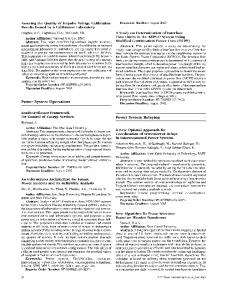
a decentralized physical entity) and a flexible upgrade of selected network functions. Another important challenge is the way that end-to-end QoS is handled assuming multiple AIVs and service requirements. 5G QoS framework needs to be more flexible and dynamic with finer granularity to better support new requirements. Some examples include services with variable packet importance (i.e. different coding gain in multimedia services) or prioritizing specific air interface variant in multi-connectivity scenarios. Furthermore, to increase the system efficiency it may be beneficial to aggregate flows with the same QoS in a single RAN radio bearer (in LTE this happens at the CN). Finally, RAN-CN interface needs to be adapted to also consider the 5G service requirements. For example, for mMTC scenarios (e.g. sensors) new interface requirements needs to be considered to cope with the high signalling cost of establishing dedicated tunnels in CN. III. SERVICE-TAILORED U-PLANE FRAMEWORK The proposed framework can be illustrated in Figure 1. Multiple services with conflicting and diverse KPI may share the same RAN. The per-service KPIs can be translated to different functional requirements and can be further mapped to different resources to meet the user demands. One important factor which will affect the actual performance of each service is the functional architecture, e.g. how to place these functions assuming multi-level hierarchical RANs, in order to meet the KPIs in a realistic deployment. In the proposed framework, each 5G service might have different functional requirements. The mapping of functions to services is closely coupled with the mapping of services to different AIVs. Here to mention, that each AIV may have different realizations based on the deployment options. For example, BSs of different types (e.g. L1/L2/L3 small cells, macro-cell) may support one or a sub-set of AIVs based on their capabilities. On the other hand, one BS may also support all the AIVs, corresponding to different spectrum considerations and PHY numerologies (mm-Wave vs Sub6GHz bands); this can be seen as single AI with which incorporates multiple variants. Based on the AIV realization and the service requirements, services can be mapped in different AIVs with different constellations. The service-toAIV mapping is key in order to identify the new requirements and the functional architecture: • 1:1 Mapping of service to AIV is the case when one service is solely mapped to one AIV. This is more relevant for critical services (e.g. URLLC) where AIV/resource isolation is of high priority.
2169-3536 (c) 2017 IEEE. Translations and content mining are permitted for academic research only. Personal use is also permitted, but republication/redistribution requires IEEE permission. See http://www.ieee.org/publications_standards/publications/rights/index.html for more information.
This article has been accepted for publication in a future issue of this journal, but has not been fully edited. Content may change prior to final publication. Citation information: DOI 10.1109/ACCESS.2017.2736579, IEEE Access
4
Select where to place functions based on a target objective (i.e. latency reduction) and RAN architecture(e.g. C-RAN D-RAN)
Map of Service to Pool of Functions and Protocols (1:N, 1:1, N:1, N:M Service to AIV mapping)
Select from 5G Services/Verticals
PDCP
PDCP
xMBB mMTC uMTC
PDCP1
PDCP2
RLC1
RLC2
RLC
RLC1
RLC2
MAC1
MAC2
MAC1
MAC2
PHY1
PHY2
PHY1
PHY2
Aggregated RLC
Aggregated PDCP
MAC1
MAC2
PHY1
PHY2
AIV 1
PDCP RLC MAC
AIV 2
... xMBBtailored functions
mMTCtailored functions
PHY1
PHY2
e.g. harmonized HARQ (III.A.3)
Aggregated MAC
uMTCtailored functions
Common functions
Figure 1 Overall Service-tailored UP Framework 1:N Mapping is the case when one service might use multiple AIVs. This requires that the UE has the capabilities to connect simultaneously to multiple AIVs (e.g. dual connectivity between Sub-6GHz and mm-Wave AIVs to ensure both coverage and capacity). • N:1 and N:M Mapping is the case of multiple services share one or more AIVs. This particular case is more efficient in terms of resource utilization and service multiplexing gains. As can be seen in Figure 1, the N:M mapping is exemplified as, where the xMBB and mMTC services may share one AIV, whereas dedicated AIV is assumed for uMTC to allow for service isolation. After the step of selecting the functions / protocols that can be mapped to different services; the second step to map these functions to the RAN deployment and which may affect the performance and to select the aggregation of AIVs in order to allow the efficient utilization of resources by multiple services. The aggregation of function is performed per AIV and the functionalities can be categorized in two parts. The servicetailored functions or parameterization of functions and the common functionalities which are identified based on the aggregation of protocols. In the sections below, a more detailed analysis of the two aforementioned steps is provided. •
A. Service-tailored functional design 1) Requirements for novel functionalities a)
Multi-AIV Support
In NR, each AIV can be characterized by different sets of physical layer features (waveform, multiple access scheme, frame structure, numerology, etc.). Assuming multiple AIVs as part of NR, the AIV-to-resource mapping is a key control functionality closely coupled with UP design. Semi-static AIV to Resource mapping: In this case, the mapping between AIV and spectrum is fixed for a given time period and is performed in PDCP. RAN allocates AIVs to time/freq. resources according to Radio Resource Control (RRC) or Operations, Administration & Maintenance (OAM) settings. However, the mapping can be updated based on the load, traffic volume, and radio condition changes. In this case, backhaul is not required to be ideal between BSs supporting different AIVs. Dynamic AIV to Resource mapping: In each TTI, time/frequency resources can be allocated dynamically per AIV in MAC. This is ideal for high dynamic scenarios such that radio resource requirements for each AIV are very dynamic accordingly. MAC layer assigns radio resources to each AIV, and further determines the time/frequency resource allocation to services using certain AIV at per TTI basis. For this case, service multiplexing level can be high with proper Radio Resource Management (RRM) algorithms; nevertheless this requires ideal backhaul between nodes (or co-location of nodes) supporting different AIVs.
2169-3536 (c) 2017 IEEE. Translations and content mining are permitted for academic research only. Personal use is also permitted, but republication/redistribution requires IEEE permission. See http://www.ieee.org/publications_standards/publications/rights/index.html for more information.
This article has been accepted for publication in a future issue of this journal, but has not been fully edited. Content may change prior to final publication. Citation information: DOI 10.1109/ACCESS.2017.2736579, IEEE Access
5 b)
Support for high frequencies (mmWave)
mmWave radio is envisioned as a key enabler for providing high capacity in 5G RAN. However, due to the path loss limitations in high frequencies, directional antennas with adaptive beam-forming and overlapping coverage are going to be used to exploit the benefits of operation in mmWave radio and ensure high coverage. In the mmWave radio, the main challenges regarding UP design are the following: • High penetration loss of mmWave frequencies can severely deteriorate the performance and hence, maintaining reliable connectivity is a challenge especially for delay critical services. • Wireless channel conditions and link quality can change significantly during movement of users, calling for fast RRM decisions and multi-connectivity support. User mobility also causes significant and rapid load changes and handovers due to small coverage areas of access nodes. Therefore, connection management and load balancing in conventional RRM functionalities need to be revisited to cope with the aforementioned challenges [7] • Due to highly directional transmissions, crosslink interference characteristics become much different from sub-6 GHz systems. For example, there can be flashlight effects (an interfering beam hits a user). From UP design point of view, it is recommended to adapt MAC design for high directivity. In 3GPP, beam management [8] is discussed as a key functionality to meet the capacity and coverage requirements by performing resource-to-beam allocation and beam sweeping / steering at MAC / Lower Layer. The aim of the beam management is to maintain connectivity between UE and a serving access node during mobility and radio environment change. From a set of candidate beams, it would be dynamically decided in which beams each user can connect to and what should be the beamto-resource allocation. To this end, one important aspect is the RAN/CN interface options which will provide requirements to the RAN design (e.g. the RAN design might need to be adapted in order to be able to meet different interface options, given the physical deployment). On the other hand, the service requirements might necessitate the use of certain RAN/CN Interfacing options to be able to meet certain KPIs (e.g. low end-to-end latency). 2) Enhancements to Existing Stack Due to the stringent latency requirements, as imposed by certain 5G services, the air interface protocol processing delay is a key consideration before re-visiting the protocol design, especially for multi-level Ultra Dense Networks (UDNs) with various multi-connectivity options. In Table 2, the contributions of different L2 functions to the overall processing delay are exemplified for 3GPP LTE system. We can observe that PDCP introduces major contribution to L2 latency, but also functions like header processing overall represent considerable contributions. In LTE, traffic can be handled differently per bearer in RLC/PDCP layers, but some functions are more static with limited flexibility, e.g. different RLC modes, Robust Header Compression (RoHC) profiles. In MAC/PHY traffic is multiplexed across bearers given the channel prioritization and other constraints. Hence, air-interface protocols can be
potentially grouped in “per bearer” and “across bearer” protocols. Given that in 5G services, RLC functionalities can be either moved together with PDCP (e.g. for MTC) or together with MAC (due to ARQ timing constraints), an alternative layering could be envisioned as a candidate solution to allow for service-tailored optimization of functionalities. Table 2 L2 Latency Contributions in LTE [9] Sublayer PDCP
RLC
MAC
Function ROHC De-ciphering Header processing Reassembly Re-ordering Header processing De-mux Header processing
Overall Latency contribution 20.01% 59.16% 7.83% 8.60% 0.40% 1% 0.84% 2.16%
The two-layer approach proposes a) the Lower Layer with traditional MAC and flexibly some RLC functions given the service requirement and b) the Upper Layer which includes traditional part of RLC, PDCP and some modified functions. In this proposal, processing gains can be achieved, in terms of latency, due to less header processing, single duplication detection and re-ordering, modular re-transmission control (instead of MAC, RLC, PDCP, two levels of re-transmission are proposed). This architecture can better deal with multiconnectivity and internal RAN functional split (Upper layer can be centrally deployed and have multiple independent Lower layer entities (corresponding to different AIVs). Below, we present some key considerations for the configuration of functions, which can be tailored for the three main 5G service types. • In xMBB, in order to accomplish the ultra-high throughput KPI, a key consideration is to enable the operation in higher frequencies, which can offer much higher bandwidth. Furthermore, high centralization of UP functions, as well as coordinated multipoint transmission, are envisioned as key technologies to meet the target KPIs. • On the other hand, uMTC is a service type which requires ultra-high reliability and low latency for time critical use cases (e.g. vehicular safety, eHealth). For achieving ultrahigh reliability, multi-connectivity / carrier aggregation (CA) can be seen as key technology enabler. In particular with the proposed layering, the upper layer will be able to connect to multiple lower layer entities; thus potentially lowering the processing delays (taking also into account the re-transmission processes). To this end, due to the small and fixed size of the packets, function like segmentation is not required; and fixed size Logical Channel Prioritization (LCP) can be used at Lower Layer. • In mMTC service type, one of the main KPIs is to maximize the connection density. Since, the traffic requirement is low, the devices are expected to be static (e.g. sensors) and the density is expected to be high, group-
2169-3536 (c) 2017 IEEE. Translations and content mining are permitted for academic research only. Personal use is also permitted, but republication/redistribution requires IEEE permission. See http://www.ieee.org/publications_standards/publications/rights/index.html for more information.
This article has been accepted for publication in a future issue of this journal, but has not been fully edited. Content may change prior to final publication. Citation information: DOI 10.1109/ACCESS.2017.2736579, IEEE Access
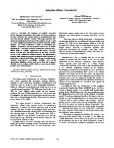
6 based functionalities both in lower and upper layer are envisioned. Further, some functions related to mobility can be disabled. Figure 2 illustrates some exemplary functions in the enhanced two-layer protocol stack. Some functions can be seen as control logics closely coupled with the legacy UP functions.
xMBB
-Ciphering -RoHC 5G Upper -ARQ (per segment) -Packet Re-ordering -Duplication detection -Segmentation / Concatenation
5G Lower
-MAC Multiplexing -Dynamic Beam Management -Dynamic AIV resource mapping -Scheduling (UE) -Logical Channel Prioritization -DRX / DTX -HARQ -RACH
5G Upper
-No Ciphering -Optional RoHC -Re-transmission (PDCP level) -Semi-static AIV to resource mapping
5G Lower
-Fixed size LCP -Optional MAC Multiplexing -Flow-based QoS BSR -Prioritized RACH, Scheduling(UE) -Chase-and-combining HARQ
uMTC
mMTC
uMTC cases assume no multiplexing at Lower Layer / MAC.
-Optional RoHC 5G Upper -Group-based Scheduling -Semi-static AIV to resource mapping
5G Lower
-MAC Multiplexing -Scheduling (UE) -Fixed Size LCP -HARQ optimized for coverage -Group-based RACH
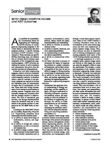
Figure 2: Exemplary Service tailored U-Plane Protocols /Functions in NR In Figure 3, an indicative comparison on the UP L2 processing latency is provided. The benchmark is the LTE eNB processing latency which is 1ms for the UP [10]. It is worth mentioning, that the latency strongly depends on factors like the TTI size and the processing capabilities at RAN; hence only a simplified scenario is exemplified to better capture the trend when we enable/disable functions in a service-tailored manner. Moreover, since the functions strongly depend on the RAN/UE characteristics, for the uMTC service type we present two cases: uMTC1 or no/low mobility use cases and uMTC2 for high mobility scenarios (e.g. for vehicular safety, assuming high mobile cars). The configuration for different services can be as follows: • For xMBB, marginal gain is achieved by having less header processing due to the two-layer approach. • In mMTC, most Upper Layer (PDCP and RLC) functions are disabled; however we assume an aggregation layer (on top of PDCP) for group-based Upper Layer functionalities. • uMTC1 is similar to mMTC however the processing may have higher latency, since it involves also packet reordering / assembly functions in Upper Layer. • For uMTC2, due to the expected frequent handovers and multi-connectivity support, upper layer includes ciphering; however RoHC is not included as well as RLC functions, to further decrease the latency. Also, both
Figure 3 L2 UP latency comparison 3) Common RAN Functionalities – Harmonized HARQ As mentioned above, the functional design will require some service-tailored functions; nevertheless there should be some functionalities which might need to be modified and harmonized in order to support all services. This is more relevant for scenarios where multi-AIV aggregation for the N:1 and N:M mapping of services to AIVs. There, the harmonization of functions will be required to allow for protocol aggregation. Below, a harmonized HARQ functionality is proposed as key example for common functionalities which are required at the 5G UP design. In order to satiate diverse service requirements expected in 5G, retransmission process has to be rethought compared to LTE-A. A flexible and enhanced HARQ design, which is configurable as per service, is desirable. The following features are distinctive in such a design [17]: • HARQ timings proportional to scalable TTI: Dynamically scalable TTI sizes for each scheduling instant of a user. For latency sensitive data, scheduling in short TTIs (uMTC) and scheduling in longer TTIs (xMBB) for larger data loads. • Asymmetric UL/DL operation: UL & DL coverage is asymmetric. UL requires longer transmission time for coverage challenged terminals. DL could still serve such users with short TTIs (due to higher transmit power). Thus, transmission times for sending UL and DL information must be allowed to be set differently. • Configurable number of stop and wait channels per user per link direction.
2169-3536 (c) 2017 IEEE. Translations and content mining are permitted for academic research only. Personal use is also permitted, but republication/redistribution requires IEEE permission. See http://www.ieee.org/publications_standards/publications/rights/index.html for more information.
This article has been accepted for publication in a future issue of this journal, but has not been fully edited. Content may change prior to final publication. Citation information: DOI 10.1109/ACCESS.2017.2736579, IEEE Access
7
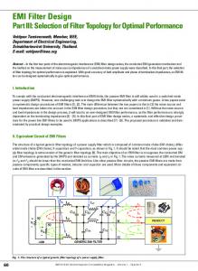
Figure 5 Exemplary DL HARQ RTT (top) and UL HARQ RTT (bottom)
Figure 4 DL (top) and UL (bottom) HARQ RTT In order to study the HARQ timings, Figure 4 describing DL and UL HARQ RTT respectively are considered. In DL, HARQ RTT is measured from the time of transmitting the scheduling grant and payload in DL, until the gNB can begin a new transmission or corresponding retransmission over the same Stop-and-Wait (SAW) channel. The DL HARQ RTT is measured as Trtt − DL = TDL −tx + 2TP + TUE + T A / N + T gNB , where TDL −tx is DL transmission time, TP is propagation time,
TUE is UE processing time, TgNB is gNB processing time and TA / N is ACK/NACK transmission time in UL. In UL, HARQ RTT is measured from the time the grant is transmitted from gNB until start of subsequent ACK/NACK transmission at gNB. The UL HARQ RTT is measured as Trtt − UL = TUL − tx + 2TP + TUE + Tg + TgNB , where TUL −tx is
UL transmission time and Tg is grant duration in DL. It is assumed that transmit and receive TTI are time aligned at BS and timing advance is applied to the UE TTI alignment, i.e., UE transmit and receive TTIs start TP before and after BS TTI respectively. Thus effect of TP is nullified. Further, number of SAW channels must be sufficiently large to keep constant flow of data transmission [17]. The minimum number of SAW channels required to avoid HARQ stalling is given as N SAW ≥ Trtt TDL −tx .To allow continuous transmission in DL, number of SAW channels needs to be selected based on TTI size in DL, along with bundling feedback in UL. For instance, with TDL −tx = 0.2 ms and TUL −tx = 1 ms, UE must bundle 5 feedback messages and transmit them at once. i.e ACK, if all 5 HARQ processes are received correctly, NACK otherwise. If bundling is not used then there will be less active HARQ processes affecting throughput.
Figure 5 demonstrates HARQ RTT in DL and UL. TTI is assumed to be 0.2 ms and processing times at UE and gNB ( TUE , TgNB ) are assumed to be 0.3 ms [17]. Fig 6-bottom shows the case, where acknowledgement time in UL is less than 0.1 ms. In such case, RTT target of 1 ms for uMTC can be met (given TDL −tx < 0.4 ms). The minimum DL HARQ RTT in LTE is 8 ms, the reduction observed here in comparison is due to flexibility in both frame structure and HARQ timing. The RTT target of 1 ms for uMTC cases can be met in UL for Tg < 0.1 ms and TUL −tx = 0.2 ms (indicating a UE in good coverage). Table 3 shows the key functionalities in HARQ design for each service type and their target KPIs. These functionalities need to be configured as per link/service requirements. xMBB requires higher throughput/spectral efficiency, sometimes even at cost of latency. Thus, scalable TTI is preferred, which can be even longer depending on constraints. Avoiding stalling of HARQ processes is another key aspect for xMBB services. This can be facilitated by enabling HARQ feedback bundling. Further, instead of having single bit ACK/NACK multi-bit richer feedback will allow improving throughput further. Table 3 Key functionalities for harmonised HARQ Harmonised HARQ framework xMBB uMTC • •
• •
Scalable TTI ACK/NACK bundling Larger HARQ buffer Multi-bit feedback
Higher throughput, spectral efficiency
• Scalable TTI (shorter) • Multi-bit feedback • Early feedback
Lower latency
mMTC • Scalable TTI (longer) • Smaller HARQ buffer • Small Packet HARQ process
Larger coverage, energy efficiency
2169-3536 (c) 2017 IEEE. Translations and content mining are permitted for academic research only. Personal use is also permitted, but republication/redistribution requires IEEE permission. See http://www.ieee.org/publications_standards/publications/rights/index.html for more information.
This article has been accepted for publication in a future issue of this journal, but has not been fully edited. Content may change prior to final publication. Citation information: DOI 10.1109/ACCESS.2017.2736579, IEEE Access
8
In case of uMTC, latency is the key focus. Scalable TTI and HARQ timings are essential, preferably shorter. Richer feedback will help in reducing latency by allowing more information about how close the receiver was at decoding the failed HARQ transmission [17]. Early feedback will allow the prediction of success of decoding in advance to send out ACK/NACK. For mMTC, main concern is energy efficiency and coverage. The TTI can be longer compared to uMTC and xMBB. Small packet HARQ process is to be supported with keen focus on energy efficiency. B. Service-oriented Functional Architecture 1) Service-tailored functional split considerations The aggregation of multiple AIVs is discussed in literature [11] as key enabler for providing harmonized protocol configuration assuming multiple air interface design options. The benefits of UP aggregation include increased throughput, pooling of resources and support for seamless mobility, reduced complexity in the BSs and the end devices (as less functionalities may need to be implemented), lower delay in case of switching between AIVs (as this can happen on a rather low protocol layer), and less standardization and implementation effort. One of the RAN design questions is how tight novel AIVs are expected to be integrated with each other and with legacy technologies (e.g. LTE evolution) and on which level different transmission forms should be aggregated. The loosest integration would occur in a flow level with IP as aggregation layer where each flow terminates in a common CN for the multiple AIVs, including the evolution of LTE. In the case of RAN solutions, considering the definition of UP aggregation explained above, examples of protocol solutions are the following [12] : • PDCP as the aggregation layer on the top of multiple RLC/MAC/PHY layers can be used in cases of non-colocated access deployments with non-ideal backhaul. An example where this split is applicable is the case of nonstandalone operation (NR and eLTE interworking) [13].[15] • RLC/MAC as the aggregation layer on the top of multiple PHY layers. This particular case is more applicable for co-located nodes or nodes with ideal backhaul, since there tight timing constraints for harmonizing MAC. This could be the case for 2 or more 5G AIVs (e.g. in high and low frequencies). Protocol aggregation is an essential part for providing multiAIV connectivity to the end user in order to boost the performance, mainly in downlink, and also enhance the diversity by associating different AIVs to users based on the user/service requirements in both uplink and downlink. MultiAIV connectivity has roots from 4G dual connectivity, wherein a user equipment can receive data from two different transmission points called as Master eNB and secondary eNB [14]. Dual connectivity solutions aim to take into account nonideal X2 backhaul between the cells and aggregation over different carrier frequencies. The main advantage of dual connectivity is to improve robustness (in particular mobility robustness) because of the existence of multiple data paths to the user [15][16]. Dual connectivity solutions [14] can be
realized by either splitting the data in the core network, or by splitting the data at the MeNB. As compared to 4G dual connectivity, 5G systems may utilize larger number of frequency bands i.e. both high frequency bands and low frequency bands, and larger number of connected cells. Thus, future 5G systems can utilize multiconnectivity solutions by using multiple cell groups and multiple bands at the same time. Multi-connectivity can thus be a rich source of transmit diversity in the network, which could be immensely beneficial for use cases such as ultrareliable communications. One important aspect is how the UP design can incorporate multi-connectivity solutions for simultaneously supporting multiple services. Notably, while considering different aggregation points in the protocol stack, the impact needs to be analyzed in the context with different architectural variants (centralized, distributed and configurability of the protocol layers). Not all the functions provided by different protocols are applicable to all services because they might add to the complexity and overhead affecting the overall performance. Some example approaches to multi-connectivity solutions using a split bearer for machine type communications is shown and discussed below. The same examples illustrate the configuration of protocol stack and aggregation of different service types.
Figure 6 (top) Split bearer with independent RLC, (middle) Split bearer with split RLC (bottom) Split bearer with duplication In Figure 6, two different services, namely extreme mobile broadband and mission critical machine type communications are shown in different colors (i.e. grey and blue). In order to ably support multiple services while also keeping service specific functionalities, and simplify handling of mobility
2169-3536 (c) 2017 IEEE. Translations and content mining are permitted for academic research only. Personal use is also permitted, but republication/redistribution requires IEEE permission. See http://www.ieee.org/publications_standards/publications/rights/index.html for more information.
This article has been accepted for publication in a future issue of this journal, but has not been fully edited. Content may change prior to final publication. Citation information: DOI 10.1109/ACCESS.2017.2736579, IEEE Access
9 robustness during handover, different PDCP and RLC entities are enabled for each of the services. This solution realizes multiplexing of flows at a protocol layer, which allows for service specific configuration of the protocol functions. In such a case, while a uMTC service flow can be configured with RLC AM, an xMBB service flow may configured with RLC UM thus allowing for cross-optimization between the flows. As can be seen in the examples above, multiconnectivity solution supports three different flows, uMTC from master gNB, uMTC from secondary gNB, and xMBB from secondary gNB. A unified MAC entity may further allow for cross-service scheduling and resource optimization within one transmission node, while at the same time harmonizing MAC functions across different transmission nodes. Furthermore, master gNB and secondary gNB may utilise a harmonized PHY layer, wherein band-specific functions are enabled at the secondary gNB while reusing PHY definitions to support MAC layer harmonization. While the example above has been shown for simplicity, a generic multiconnectivity solution may incorporate more number of cells, and additional services such as mMTC. 2) Re-transmission considerations in functional split scenarios This section discusses one key RAN process which will need to be modified in different functional split scenarios and in particular for a case of a D-RAN with multiple hops and selfbackhauling. In this case the re-transmission might happen with different HARQ/ARQ schemes and parameterization, to achieve certain KPIs. Below, some options are presented that can be candidate solutions for employing service-tailored functional split. In a multi-hop/self-backhauled scenario, e.g. relay or mesh network, some additional considerations are required in the design of HARQ/ARQ protocol. The different hops in a multihop/self-backhaul scenario may differ in terms of radio link conditions e.g. SINR, Reception/Transmission (Rx/Tx) Capabilities (e.g. number of antennas) and dynamic Time Division Duplexing (TDD) Configuration etc. Hence, RRM (Radio Resource Management) mechanisms such as link adaptation, segmentation etc. are required per hop. Essentially, in a mobility scenario for a fully reliable use case, separated mechanisms are required to be able to ensure reliability endto-end for both links. Due to the aforementioned reasons, there are three possible ARQ protocol architectures for the multi-hop/self-backhauled scenarios [37]: • Option. 1 “Per hop HARQ/RLC ARQ”: The single-hop ARQ architecture. This indeed violates the assumption on having an end-to-end mechanism discussed above, but is included for further comparison. • Option 2 “End to End RLC ARQ”: Again, the same single-hop ARQ architecture is utilized over each hop as in Option 1 above – but now with only HARQ and no RLC over each hop. A higher layer RLC (inclusive of ARQ, segmentation etc.) is instead placed only at the endpoint nodes, i.e., in the BS and the UE. • Option 3 “Two Layered RLC ARQ”: This is essentially a combination of the two other ARQ architectures with a
single-hop ARQ including HARQ and RLC ARQ for each hop and – in addition – an extra higher layer RLC is placed on top of this in the end-point nodes The three protocol architecture options are illustrated in Figure 7. In the end-to-end RLC layer (Option 2/Option 3), the transmission buffer could be placed at RLC at BS or UE and each transmitted packet until it is positively acknowledged by the receiving RLC could be kept in the buffer. Thereafter, the packet is removed from the buffer. The RLC at the transmitter needs to set ARQ retransmission timer depending on the total end-to-end delay, in order not to avoid pre-mature retransmissions.
Figure 7 The three possible multi-hop/self-backhauled ARQ architectures (including HARQ and RLC ARQ for each hop) and an additional higher layer RLC at the end nodes. Relay ARQ Relay ARQ is a modified version of the two layered ARQ architecture (Option 3). It integrates the ARQ of the higher RLC layer into the per-hop relay RLC layer, as shown in Figure 8.
Figure 8 Multi-hop Relay ARQ protocol architecture. Briefly the idea is that the temporary retransmission responsibility is delegated, from the sender, between sender the relay node in order to perform the retransmissions only in the hop which is encountering the failure. Note that the source
2169-3536 (c) 2017 IEEE. Translations and content mining are permitted for academic research only. Personal use is also permitted, but republication/redistribution requires IEEE permission. See http://www.ieee.org/publications_standards/publications/rights/index.html for more information.
This article has been accepted for publication in a future issue of this journal, but has not been fully edited. Content may change prior to final publication. Citation information: DOI 10.1109/ACCESS.2017.2736579, IEEE Access
10 node still has the retransmission responsibility to ensure E2E reliability. Regardless, whether the two Layered ARQ (Option 3) or the relay ARQ architecture is exposed, it is only in the endpoints (e.g. BS and UE) where in-order delivery of RLC SDUs shall be employed since the higher protocol layers requires in-order delivery of data. IV. IMPACT OF 5G ARCHITECTURE TO SERVICE-ORIENTED UP DESIGN
The 5G Architecture may provide some key considerations as well as limitations for the realization of the Service-oriented UP design. Some key considerations will be due to the deployment of nodes and functionalities as well as the RANCN interface options. In particular as can be seen in Figure 9, in this section the effect of CP/UP split options, the Slicingawareness and the RAN/CN protocol options are investigated as key factors that can affect the UP design considerations. Slice-aware CP
N2
CP RAN/CN Interface Considerations
Impact of RAN Deployment to UP Design
UE
Uu
DUs
CN-C
N3
CU
CN-U
Figure 9 Overview of 5G Architecture Impact on UP Design A. CP / UP split considerations The network functions (NFs) of a wireless network are typically categorized into three groups: The UP is responsible for forwarding data from the source to the destination, including the corresponding processing. The control plane (CP) controls the UP, for example in terms of setting the routing path of a packet or of radio resource management. The CP also provides a set of other functionalities such as connection / mobility management and broadcasting of system information. Besides CP and UP, a network also requires management and operation functions. The separation of CP and UP according to the SDN concept is a recent trend in the definition of the 5G architecture [18][19][20]. It requires categorizing all NFs as being either part of CP or UP, based on functional decomposition [21]. Any kind of interaction between CP and UP is supposed to happen through standardized interfaces. For the core network a separation of CP and UP functions is already partially realized e.g. in LTE with the Mobility Management Entity as the main CP element and the Serving and Packet Gateways as UP elements. However, this separation is not complete, e.g. the Packet Gateway contains CP functions. An enhanced separation of CP and UP for the ECP is under study in [21]. The motivation for a full separation of CP and UP is threefold: Firstly, a standardized interface enables a consistent control over UP network elements and NFs from different vendors / manufacturers, e.g. in terms of interference management for ultra-dense networks. Secondly, a replacement or upgrade of a CP function often requires also the replacement of coupled UP functions and vice versa. Avoiding this might offer significant
cost savings. Finally, the independent evolution of CP and UP could make the rollout of new NFs faster thus enable a more flexible network. However, there are also significant challenges that make a full separation complex, mainly the tight coupling of CP and UP in the RAN [22]. In addition, extensive standardization is required. Integrating new in the future interfaces in a proprietary manner in combination with standardized ones is not a suitable solution, as it would destroy the benefits of a CP/UP split. For example, a flexible change of CP NFs in logical network elements would not be possible any more if only selected UP NFs support certain proprietary interfaces. Additional effort in terms of testing is required to guarantee the interoperability of CP and UP functions from different sources (shifting the effort to system integrators supporting the operators instead of doing this work at a single vendor). In RAN deployments, due to the strong coupling of UP with control logics, the complete CP/UP separation, might not be feasible for all different deployments. In particular, we may have real-time Scheduling (or Fast RRM) functionalities which will require per TTI scheduling. In case of D-RAN, the de-coupling of fast RRM will require ideal BH / FH between the control part of BS and the data processing part of BS. Hence, below we show some cases where we partially split some C-Plane functionalities. Since there might be multiple interactions between independent functionalities, we group them in three types of C-Plane functionalities: 1) Fast RRM or Real-time Scheduling, 2) Slow RRM or Non-Real time Scheduling (Cell Re-Selection, Connection Mobility Control (CMC), Load Balancing (LB), Inter-cell Interference Coordination (ICIC)) and 3) RRC functions. In the first option, the complete separation of CP-UP Plane is provided. The main advantages of this option are the high gains due to Centralized Scheduling and the ability to support tight resource cooperation between multiple cells (e.g. virtual cell concept). On the other hand, one of the key drawbacks of this option is that it requires ideal BH to meet the tight latency requirements (for per TTI scheduling). In the second option, the CP/UP separation involved the separation of RRC and Slow RRM; hence Real-time / Fast RRM remain at the distributed unit (DU). This is a good compromise for Distributed-RAN (D-RAN) deployments with non-ideal BH, since the real-time RRM is performed at the DUs. On the other hand, there might be dependencies between RRM functions that will require additional signalling. In Figure 10, we show the two different options and how they can be mapped to different RAN deployments. In particular, for a D-RAN deployment, the separation of RRC and Slow RRM (option 2) seems more reasonable due to the wireless backhaul which can be non-ideal. On the other hand, for an exemplary 5G scenario, where mmWave access points (APs) can provide hotspot coverage to enhance capacity, the separation of C-Plane part at a BS operating in low frequencies (e.g. LTE coverage) will allow for efficient 5G operation by centralizing/pooling resource gains and centralized resource management. This option however, requires ideal BH/FH between the access points, as mentioned above.
2169-3536 (c) 2017 IEEE. Translations and content mining are permitted for academic research only. Personal use is also permitted, but republication/redistribution requires IEEE permission. See http://www.ieee.org/publications_standards/publications/rights/index.html for more information.
This article has been accepted for publication in a future issue of this journal, but has not been fully edited. Content may change prior to final publication. Citation information: DOI 10.1109/ACCESS.2017.2736579, IEEE Access
11
D-RAN deployment –with small cells and