or a light stage, and made additional restrictive assumptions ..... ing samba dancing (Fig. 10-a,b) ... fusion of dynamic shape and normal capture for high-quality.
Shading-based Dynamic Shape Refinement from Multi-view Video under General Illumination Chenglei Wu1,2
Kiran Varanasi1 Yebin Liu1 Hans-Peter Seidel1 1 MPI Informatik 2 Intel Visual Computing Institute
Abstract We present an approach to add true fine-scale spatiotemporal shape detail to dynamic scene geometry captured from multi-view video footage. Our approach exploits shading information to recover the millimeter-scale surface structure, but in contrast to related approaches succeeds under general unconstrained lighting conditions. Our method starts off from a set of multi-view video frames and an initial series of reconstructed coarse 3D meshes that lack any surface detail. In a spatio-temporal maximum a posteriori probability (MAP) inference framework, our approach first estimates the incident illumination and the spatiallyvarying albedo map on the mesh surface for every time instant. Thereafter, albedo and illumination are used to estimate the true geometric detail visible in the images and add it to the coarse reconstructions. The MAP framework uses weak temporal priors on lighting, albedo and geometry which improve reconstruction quality yet allow for temporal variations in the data.
1. Introduction Recent advances in computer vision have made it possible to reconstruct dynamic scenes from the real world into 3D mesh representations (e.g., [20, 7, 6, 4]). This is done by capturing the scene from multiple synchronized video cameras and building the 3D shape from photometric cues, with the requirement that the reconstructions are geometrically and topologically consistent over time. These 3D shapes show plausible deformations up to medium scale detail, but often lack true detail at the finest level. As an example, a static laser-scan can be deformed to mimick the motion of the real scene, but any fine scale detail thus obtained appears baked into the surface in the rest of the frames and does not capture the soft wrinkles on clothes and skin as can be observed from the images [20, 7] (Fig. 1(d)). Some approaches attempt to reconstruct such detail through multiview stereo from scratch or stereo-based refinement, but even then the detail in reconstructions is limited.
Christian Theobalt1
In this paper, we propose a method that exploits knowledge about how a scene is lit and how it appears shaded in images to refine captured dynamic scene geometry. Certain previous approaches have exploited shading and photometric stereo cues for capturing shape detail, for instance for facial performance capture [4, 23]. However, they required controlled studio lighting through calibrated colored lights or a light stage, and made additional restrictive assumptions about the scene, such as that surface albedo is constant [11]. In contrast to these past methods, in this paper, we propose a passive shape refinement method that attempts to reconstruct highly detailed spatio-temporally coherent 3D geometry under general illumination conditions (Fig. 1(c)). We accept as input a sequence of multi-view images captured from a set of synchronized and calibrated cameras. Considering the state of the art in marker-less 3D motion capture systems (e.g., [10, 6]), we also assume that temporally coherent 3D meshes were reconstructed that lack any fine shape detail. We consider the estimated motion between the meshes to be accurate only up to a coarse level. From this input, we try to capture high quality surface detail such as folds and deformation of human body or cloth. For every time step of video, we explicitly estimate the incident illumination in the scene based on the reconstructed shape, make an estimate of the albedo distribution on the surface, and then use this information together with the lighting equation to recover the fine-grained structure and orientation of points on the surface. We assume a Lambertian model of reflection where incident lighting is given by an environment map that is parameterized in the spherical harmonic domain [17], and where surface properties are given by a spatially-varying albedo map. We mathematically formulate this in a maximum-a-posteriori (MAP) estimation framework, where we enforce a soft temporal coherency in estimated lighting, albedo and refined geometry. This way, also the environment map, and surface albedo can change over time within reasonable bounds, e.g., when a subject walks along a room with several distributed lights, or when shifting apparel changes the albedo of a surface point over time. Our major contributions in this paper are as follows.
Figure 1. Shading based Shape Refinement : (a) Captured image. (b) Smooth model obtained by tracking. (c) Our result of spatio-temporal shape refinement. (d) High-resolution geometry of a laser scan transferred by tracking, whose baked-in detail does not correspond to (a).
1. We provide a method for adding spatio-temporally coherent millimeter scale surface geometry to coarse dynamic 3D scene models captured from multi-view video under general illumination. 2. We reconstruct time-varying incident illumination, time-varying and spatially varying surface albedo, and time-varying geometry detail, without using engineered lighting conditions. 3. We exploit the spatio-temporal information in the scene through soft temporal priors, which improves reconstruction quality but permits variations in the data. We have tested our approach on a variety of real-world scenes and show quantitatively and qualitatively that it is able to recover fine-scale dynamic shape detail that could not be reconstructed with other methods under similar unconstrained conditions.
2. Related work Visual reconstruction of dynamic 3D scenes has been investigated extensively in the recent past. Many performance capture and 3D video methods record a dynamic scene with multiple synchronized video cameras and capture geometrically and topologically consistent dynamic shape models based on photometric image cues, such as silhouettes. Vlasic et al. [20] proposed a method to track a mesh fit with a skeleton using multi-view silhouettes. Gall et al. [10] track a skeleton and mesh-based surface deformations using silhouettes and point features. Other approaches track a skeleton-less deformable mesh model [7] or a set of surface patches [5, 6], and can handle more general shapes and topologies. The above methods sample photometric information in the captured images only sparsely - by considering point features or silhouettes - and thus the reconstructed meshes capture true shape detail only coarsely. Some of these approaches deform an initial laser scan along the dynamic scene, where fine-scale static detail is permanently embossed onto the moving surface but not actually captured from images (e.g. [20, 7], see Fig. 1(d) for inspection).
Figure 2. Overview - Input to shape refinement at frame t : (a) Lighting estimate at t-1 (b) Surface albedo map at t-1 (c) Detailed surface geometry at t-1 (d) Coarse tracked model at t (e) multiview images at t. The two steps of our method : (A) lighting and albedo estimation. (B) Recovery of high frequency shape detail.
Multi-view stereo can overcome some of these limitations and capture shape detail more densely also for dynamic scenes, e.g. in the context of facial performance capture [4, 9]. However, in untextured regions stereo-based shape estimation and tracking are unreliable, and necessary regularization suppresses detail. In this paper, we estimate lighting and albedo under general illumination, and then use shading to capture true dynamic detail even if texture appears uniform. In the past, photometric stereo or reflectance estimation approaches have exploited shading information in images captured under engineered controlled lighting conditions. Theobalt et al. [19] use multi-view performance capture under calibrated lighting to estimate surface normals and material properties (BRDFs) of a human. Ahmed et al. [1] integrate these normal fields to obtain true dynamic surface deformation. Wenger et al. [22] deploy the light stage a time-multiplexed lighting set up to integrate images taken under several lighting conditions into a single 3D mesh with material properties (BRDF). Vlasic et at [21] use a multiview video captured in a light-stage to capture detailed geometry of a moving human by means of photometric stereo.
Hernandez et al. [11, 12] develop a cheaper system for estimating high quality 3D geometry (but not the BRDF) by capturing the scene under a few colored lights. Nehab et al. [15] refine geometry obtained from laser-scans using photometric normals. Although with such methods high quality geometry is captured, the algorithms are constrained by requiring controlled lighting systems and by making restricting assumptions about the scene, e.g. that the surface has constant albedo. In contrast, our approach operates under general uncontrolled lighting and can handle surfaces with spatially-varying albedo. Related to our idea is the approach by Popa et al. [16] who synthesize wrinkles on captured coarse geometry by finding shading features in images. However, their approach does not perform a true geometric reconstruction like ours, but uses a heuristic to synthesize bumps near shadig gradients. A prerequisite for our shape refinement strategy is a new approach for estimation of incident illumination which capitalizes on the recent literature on modeling the irradiance of a Lambertian scene through spherical harmonics [3, 17]. Various methods for static 3D surface reconstruction have been proposed that are based on these advances. Basri et al. [2] propose a photometric stereo method that uses images taken under multiple unknown lighting situations. Wu et al. [24] propose a method that accepts multi-view images of a static object with constant albedo under single lighting. More general reflection models have also been considered for static scenes [26, 25]. It is possible to employ such methods of static shape refinement on each frame of a sequence and reconstruct the fine detail of the shape from shading. However, such reconstructions would suffer from temporal flicker. In contrast, we propose a method that implicitly produces a flicker-free reconstruction by exploiting knowledge on the dynamic scene motion. Using weak temporal priors, our method estimates time-varying general illumination, as well as spatially and temporally varying albedo to ultimately reconstruct the dynamic shape with rich fine-scale detail.
3. Dynamic shape refinement We assume that a performance capture method was employed to obtain coarse mesh reconstructions at each time frame that lack true surface detail. We use the approach of Gall et al. [10] that starts from a smoothed static model of the person of around 5000 vertices (can be obtained through a static laser scan or shape-from-silhouettes) which it deforms to follow the motion in the scene. But any other such method reviewed in Sec. 2 can be used for this step. These spatio-temporally coherent meshes and the multi-view images captured under general unknown illumination form the input to our method. From this input, we perform spatiotemporal surface refinement at each frame to recover the high frequency geometry component by looking at shad-
ing cues. For refinement, we use a finer tessellated version of the coarse tracked geometry (vertex count increased to 80000), where a displacement for each vertex is found. In the rest of the paper, we refer to the coarse estimates of vertex positions and normals given by the performance capture method as low freq and the refined vertex positions and normals output by our method as high freq. We perform this refinement successively at each frame to reconstruct the entire sequence. Shading in the scene is generally an interaction result of lighting, material and geometry, which is described by the rendering equation [13]. In the general reconstruction case, all these three components are unknown. To make the problem tractable, we assume the surface to be Lambertian and employ spherical harmonics (SH) to represent the general lighting. So our refined model has three components SH lighting coefficients, albedos and surface geometry (or positions of vertices {xu }). We formulate the problem of dynamic shape refinement as estimating these three components ({lit }, {ρtu }, {xtu }) at a given frame using these estit−1 mates in the previous frame ({lit−1 }, {ρt−1 u }, {xu }) and the coarse performance capture model in the current frame ({ˆ xtu }). We develop a two-step algorithm that is visualized in Fig. 2. In the first step, we estimate the lighting coefficients and the surface albedos ({lit , ρtu }) at a given frame. These are estimated based on the lighting and albedos of the previous frame and the current tracked coarse model. In the second step, based on the estimated lighting and albedos, as well as the previous refined model, the high quality geometry at the current frame ({xtu }) is recovered based on shading cues. We formulate these two steps as two MAP estimation problems with the appropriate priors, as detailed later in this section.
3.1. Shading model Using SH to represent the general lighting, the image formation model is described as (see [17, 3] for details) : 2
B(x) =
n X
ρx li Yi ,
(1)
i=1
where B(x) is the reflected radiance at surface point x, ρx is the albedo at that point, {li } are SH coefficients of the visible lighting for that point (visibility towards lighting is calculated explicitly for each vertex), Yi is the SH function determined by the surface normal and n is the number of considered SH frqeuency bands (in our experiments, we use n = 5 bands). We consider scenes captured using color images with RGB channels, so the albedo is a 3-vector containing these three components. The above equation, along with the equations derived in the following hold true for all the color channels.
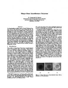
Figure 3. Lighting estimation : (a) Typical light-source distribution for real-world datasets we used. (b) Ground-truth lighting for synthetic data - SH approximation of the incoming radiance displayed onto a cubemap. (c) The lighting estimated by our algorithm
Following our assumption about piecewise uniform albedo in the scene, we employ an image segmentation algorithm [8] to segment the albedo map into surface parts of approximately constant albedo (see Fig. 4(c)). As criteria for segmentation, we provide the minimal size for each segment and the minimal difference in albedos across two segments (same parameters for all time steps). Assuming we have k different albedo parts, we formulate a global problem that updates these albedo values as well as computes the lighting coefficients at the current frame. This is defined as a finding a MAP solution that maximizes the likelihood: P (lt , ρt |I t ) ∝ P (I t |lt , ρt )P (lt )P (ρt ), t
(2)
{l1t , . . . lnt 2 } t
where l = is the n − 1 order SH coefficients for the lighting, ρ = {ρt1 , . . . ρtk } represents the albedos for segmented parts. So the cost function we define is: Figure 4. Stages for albedo estimation : (a) Input textured model. (b) Initial guess for albedos, based on the previous frame’s lighting. (c) Albedo clusters detected on (b) through segmentation. (d) Detected outliers marked in red. (e) The final albedo map.
3.2. Lighting and albedo estimation In the general case, the albedo varies across surface points. In an extreme case of high frequency texture with many surface albedos, solving for all the albedos and the incident illumination from coarse geometry is infeasible. However, in most cases it is reasonable to assume that the albedo space is restricted and that the surface comprises of patches of piecewise uniform albedo. For instance, most pieces of apparel have a dominant base color, as seen in Fig. 4. With a restricted albedo space we can simultaneously solve for albedo and lighting at each time step. Otherwise there would be an insufficient number of surface points (or shading samples) of similar reflectance seen under different orientations, which is needed to infer the incident illumination. In our method, we first obtain an initial guess for the albedo of each vertex by making two assumptions - (i) that the lighting of the previous frame applies approximately to the current frame (ii) an approximation to the high freq surface normals at the current frame can be obtained by transfering the high freq normals of the previous frame through the low freq motion estimates given by the performance capture method (described in greater detail in section Sec. 3.3). Using these initial guesses, we solve for the albedos at the current time step (i.e. an individual albedo for every mesh vertex) using Eq. (1) (Fig. 4(b)). Subsequently, we solve a global energy minimization problem to refine these albedo values over the entire shape, and to estimate the lighting conditions at the current frame.
ψ(lt , ρt ) = φ(I t |lt , ρt ) + φ(lt ) + φ(ρt ),
(3)
where φ(I t |lt , ρt ) is the shading error, φ(lt ) and φ(ρt ) are the priors for lighting and albedo in the current estimate. Specifically, as albedo segmentation may contain outliers, we use `1 norm to define the shading error, i.e. φ(I t |lt , ρt ) = kI(x) − B(x)k1 .
(4)
We require the incoming light energy and the albedo of the surface points in the current frame to be not too different from those of the previous frame, which yields the priors: 2
2
t
φ(l ) = λ0 (
n X
2 (lit )
i=1
φ(ρt )) = λ1
−
n X
2
(lit−1 ) )2 ,
(5)
i=1 k X
2 (ρtu − ρt−1 u ) .
(6)
u=1
With the lighting and albedo estimated, we detect the outliers in the albedo segmentation for each part. Examples of outliers are surface points under cast shadows (where the first bounce illumination assumption is violated) or where the surface is non-Lambertian. To detect outliers, we calculate the median absolute deviation [18] for each uniform albedo part as σi = α ∗ medianx∈S(i) kI(x) − B(x)k1 ,
(7)
where S(i) represents the uniform-albedo part i and α = 1.4826 is the theoretical correction factor [18]. If kI(x) − B(x)k1 > βσ, the surface point is considered as an outlier and will be optimized only by relying on the shape prior afterwards (in our experiments, we have set the penalizing threshold β = 2.5). We refine the lighting and albedo estimates again with these outliers excluded by solving Eq.(3) (Fig. 4(e)).
Figure 5. Handling errors in estimated geometry : (a) the geometry of the forearm is not estimated fully correctly; using an `2 -metric shading term this yields to artifacts around the visibility shadow on the torso. (b) The `1 -metric shading term prevents this artifact.
3.3. Recovery of high-frequency shape detail Now, the lighting and the albedos for the current frame are known. The next step is to estimate the fine-scale geometry of the current frame based on the images, the coarse shape model at the current frame, and the refined model of previous frame. This can also be defined as a MAP problem, the likelihood of which is: P (g t |I t , g t−1 ) ∝ P (I t |g t )P (g t |g t−1 ),
(8)
where g t and g t−1 are the geometry of the current frame and the previous frame, and I t are the current captured images. The cost function to optimize is thus ψ(g) = φ(I t |g t ) + φ(g t |g t−1 ),
(9)
where φ(I t |g t ) is the shading error and φ(g t |g t−1 ) is the prior for the current geometry based on the previous frame’s geometry. The shading error measures the difference between the observed and predicted irradiances at each vertex according to the shape estimate. We are not comparing irradiances, since that comparison is less robust if the assumptions on lighting and image-formation are not exactly met. When evaluating the energy, we use grey-scale intensities, instead of treating the three color channels separately. Our shading error is defined as : X X X φ(I t |g t ) = |rc (i, j) − s(i, j)|, (10) i
j∈N (i) c∈Q(i,j)
where i and j are vertex indices, N (i) is the set of the neighbors of the i-th vertex, c is the camera index, Q(i, j) is the set of cameras which see vertex i and j, and r(i, j) and s(i, j) are the measured image gradient and predicted shading gradient, respectively. An important step to solving this equation is determining Q(i, j), which depends on the current estimate of the 3D geometry (vertex positions xi ). A discrepency between the hypothesized scene geometry and the real geometry will lead to wrong assumptions about what surface point is visible from what camera. Such errors translate into wrongly evaluated shading cues, and thus geometry artifacts. Fig. 5
Figure 6. Importance of temporal shape prior: (a) Captured image. (b) Reconstructed model using no temporal shape prior (OneFrm method). (c) Improved reconstructed model using temporal shape prior.
shows one such error that often arises around a visibility shadow that more frontal geometry casts onto more distant geometry. Wu et al. [24] have recently proposed a shading error metric similar to Eq. (10) for the reconstruction of static 3D scenes. However, they assume a much denser set of input camera views (> 20) and better initial geometry to start with. In contrast, performance capture methods typically use only 8-12 cameras, and reconstruct a geometry that is only accurate up to a coarse scale. This makes the errors in determining Q(i, j) more damaging for our situation, and demands explicit consideration. In order to implicitly downweight the influence of these errors, without having to resort to more complex visibility computation, we employ the robust `1 metric in Eq. (10) in contrast to the `2 metric used by [24] (Fig. 5). The prior φ(g t |g t−1 ) enforces weak temporal coherency by requiring the the current high freq normal field not to be much different from the one in the previous time step transformed into the current time step : XX ˆ ti · (xtu − xtw )]2 , φ(g t |g t−1 ) = λ2 [n (11) i
u,w
where xtu and xtw are the positions of vertices u and w, vertices u w and i belong to the same mesh triangle, and ˆ ti is the propagated surface normal at vertex i based on the n already reconstructed high freq normal field of the previous frame. This propagation is done by estimating the relative transformation Ri of the low freq normals between the two frames, using a method similar to [15], such that : n ˜ti = Ri n ˜t−1 , i
(12)
where n ˜ti and n ˜t−1 are the low freq normals of the current i frame and the previous frame, respectively. Then we obtain the propagated fine-scale normal of current frame by transforming the high freq normal of previous frame as: ˆ ti = Ri nt−1 n , i nt−1 i
(13)
where is the normal of the refined model of previous frame. We now obtain an initialization for the fine geometry at the current frame by displacing vertex positions so as to
ˆ ti }. Starting from align with the propagated normal field {n this initial estimate, the final refined vertex positions (and normals) are found by optimizing Eq. (9). In our shape refinement procedure, we give the shading term less influence when optimizing regions with low albedo. This is because such regions suffer more from camera noise. We thus include a weighing term λ2 in the shape prior Eq. (11) : λ2 = β1 (2 − ρu / max(ρi )), i
(14)
where ρu is the albedo for the vertex u, which is to be optimized, and maxi (ρi ) is the maximum albedo of the current model. Since optimizing the positions of all the vertices simultaneously might take too long, we adopt a patch-based optimization strategy that divides the surface into a set of patches and optimizes on the set of vertices belonging to each patch sequentially. This arrives at a local optimum that is usually quite robust.
3.4. Reconstruction of shape and lighting for the first frame For the first time step, we can not employ our spatiotemporal reconstruction scheme as information from the prior time instant is not available. Instead, we employ a static refinement method (referred to as OneFrm) that only uses image and coarse model information for the one time step under consideration. To this end, we first segment the shape into parts of uniform color, and assume that these are regions of uniform albedo. We then estimate lighting coefficients and albedo values using our method of Sec. 3.2, but without temporal priors. Next, we recover the high frequency surface detail using a spatial smoothness prior in Eq. (9) (instead of the shape prior from the previous frame) that requires neighboring surface vertices in a one-ring to have similar positions. This gives a reasonable estimate for the first frame. In later frames, however, we always resort to the full spatio-temporal scheme which is clearly better than using the static scheme sequentially to all time steps (see Fig. 6 and Sec. 4).
4. Experiments We test our algorithm on one synthetic sequence for quantitative evaluation, and 4 realistic captured sequences for qualitative validation. We use the performance capture method of Gall et al. [10] that uses an initial smooth mesh of around 5000 vertices to track the performance. We obtained this by smoothing a static laser scan of the performer (for real data,e.g.,Fig. 1(b)) or by smoothing a ground truth input mesh (for synthetic data, Fig. 7(b)). Refinement is computed on the 80000 vertex versions of the coarse models (see Sec. 3).
Figure 7. Shape refinement results on synthetic data : (a) One of the rendered images that we provided as input. (b) The smooth low-freq model obtained by tracking. (c) Our spatio-temporal shape refinement result (d) Ground-truth model (e) Difference from groundtruth for (b) in the inset region (color-coded error w.r.t. ground truth - red=high). (f) Difference from groundtruth for (c).
Synthetic scene We rendered a synthetic motion sequence of a female dancer of length 60 frames from 12 circularly arranged virtual cameras of resolution 1296 × 972. Surface albedo distribution was manually specified (5 regions of similar albedo), and the scene was rendered using a single area light from an overhead position (Fig. 7(a) shows one rendered frame). We applied the performance capture method to all the frames; we then performed static refinement (OneFrm) on the first time step and spatio-temporal refinement on all subsequent ones. Fig. 7(c) and Fig. 7(d) show the refined model and the ground truth, respectively. We compare the accuracy w.r.t ground truth of albedo estimation between the OneFrm and spatio-temporal refinement methods in Fig. 8(a). We use the normalized correlation coefficient to compare the estimates. This figure clearly demonstrates that by using spatio-temporal information for estimating lighting and albedo values, higher accuracy is achieved. Fig. 3 shows a visual comparison of our lighting estimate with the ground truth, illustrating the high quality of our estimate (more results in additional document). We also evaluated the accuracy of the reconstructed high-resolution geometry by our algorithm. In Fig. 8-(b,c), we show the errors in normal orientation and position as compared to the ground truth. Here, we also compare our method to the OneFrm method, and to the coarse tracked model as the baseline. These figures illustrate that our method reliably captures high-frequency shape detail that is not present in the coarse model. The refinement through OneFrm is understandably less accurate - especially in estimating normal orientations. The same can be visualized in Fig. 6(b,c) as spatio-temporal refinement better brings out high frequency shape details. Using the OneFrm method independently at each frame also produces temporal flicker which is absent in the reconstructions of our method. We invite the readers to see the comparison in the accompanying video.
Figure 8. Quantitative evaluation on synthetic data : (a) Surface albedo estimate accuracy. (b) Errors in the estimated normals. (c) Errors in the estimated vertex positions (normalized using the diameter of the bounding sphere of the model). Our spatio-temporal shape refinement (red curve) yields the best results.
Figure 9. Qualitative comparison with stereo refinement : (a) Captured image. (b) Our shape refinement results. (c) Stereo-based shape refinement of Liu et al [14]
Figure 10. Qualitative evaluation on real datasets : (a,c) Captured image. (b,d) Our shape refinement results. Our refinement method brings out fine-scale detail from images with fidelity. * Please look at the accompanying video for more results *
Real-world scenes We validate our algorithm on four real captured sequences, showing 3 different subjects in different types of apparel. All sequences where captured indoors with non-engineered lighting, i.e. several area light sources and spot lights on the ceiling (Fig. 3-a). The results of shape refinement on certain frames are provided within this paper. The high fidelity and dynamics of reconstructions is also shown in the supplemental video. The first two sequences show an actress wearing a sweater and jeans performing different motions, namely walking (Fig. 9) and kicking (Fig. 1), the third shows another actress in a skirt performing samba dancing (Fig. 10-a,b), and the fourth shows an actor executing a Capoeira move (Fig. 10-c,d). For the first two sequences, 12 cameras at a resolution of 1296×972 pixels are used to record at a frame rate of 44 fps. For the latter two sequences that were provided to us by the authors of [7], 8 cameras running at the resolution of 1004 × 1004 pixels are used. We show the results in Fig. 10. In all cases, our method recovers the true dynamic detail seen in the images reliably. Our reconstructions capture the true time-varying detail visible in input images, as opposed to the deforming embossed static shape detail seen from performance capture methods that deform a (unsmoothed) static laser scan (Fig. 1(d)). In Fig. 9(c), we show a qualitative comparison of our method with a stereo based reconstruction method of Liu et al. [14]. It can be observed that our method brings out finer detail than stereo.
Runtime performance We measured the runtimes of the various algorithmic components on a standard PC with a 2.66 GHz Core 2 Quad processor. Performance capture using [10] takes on average 5 − 10 s per time step. Per vertex visibility computation (one visibility environment map per vertex) takes around 10 minutes per frame. The shape refinement step takes around 6 minutes per frame. Since these three steps can be executed in parallel for processing sequences, the runtime is decided by the visibility computation step (10 minutes per frame).
Limitations On parts of the shape where image resolution is limited (for example, on the faces of the actors), our approach cannot completely recover the fine-scale detail . Reconstruction quality also depends on the tracking accuracy of the performance capture approach; large tracking errors already in the coarse model will lead to incorrect refinements. In future, we plan to investigate ways to improve low frequency tracking accuracy through our lighting estimation and shape refinement model. Another limitation is that we assume Lambertian surfaces; as such, our algorithm fails to obtain the high-frequency detail on non-Lambertian parts of the shape. Also, the assumption that the surface can be clustered into regions of uniform albedo is restricting and can be violated in some scenes. If too many different materials are present, the space of shading samples may not be sufficient in order to estimate albedo and lighting at the same time. In such cases, they may have to be spatiotemporally solved over more time instants which makes the approach more vulnerable to tracking errors.
5. Conclusion In this paper, we proposed a general method for capturing high-quality time-varying surface detail by analyzing the shading information of multi-view video sequences captured under general illumination. We make minimal assumptions about the nature of the scene, the type of motion or the lighting requirements. Starting off from coarse per time-step reconstructions, we recover incident illumination, surface albedo and fine-scale surface detail in a spatiotemporally coherent way. Our reconstruction framework uses weak temporal priors to boost reconstruction quality, but it is still able to allow for and capture temporal variations in lighting, albedo and shape.
References [1] N. Ahmed, C. Theobalt, P. Dobrev, and H. P. Seidel. Robust fusion of dynamic shape and normal capture for high-quality reconstruction of time-varying geometry. In Proc. of CVPR, 2008. 2 [2] R. Basri, D. Jacobs, and I. Kemelmacher. Photometric stereo with general, unknown lighting. IJCV, 72(3):239–257, 2006. 3 [3] R. Basri and D. W. Jacobs. Lambertian reflectance and linear subspaces. IEEE TPAMI, 25(2):218–233, 2003. 3 [4] D. Bradley, W. Heidrich, T. Popa, and A. Sheffer. High resolution passive facial performance capture. In ACM TOG (Proc. SIGGRAPH), volume 29, page 3, 2010. 1, 2 [5] C. Cagniart, E. Boyer, and S. Ilic. Free-form mesh tracking : a patch-based approach. In Proc. of CVPR, 2010. 2 [6] C. Cagniart, E. Boyer, and S. Ilic. Probabilistic deformable surface tracking from multiple videos. In ECCV, 2010. 1, 2 [7] E. de Aguiar, C. Stoll, C. Theobalt, N. Ahmed, H. P. Seidel, and S. Thrun. Performance capture from sparse multi-view video. In ACM TOG (Proc. SIGGRAPH), 2008. 1, 2, 7
[8] P. F. Felzenswalb and D. P. Huttenlocher. Efficient graphbased image segmentation. IJCV, 2004. 4 [9] Y. Furukawa and J. Ponce. Dense 3d motion capture for human faces. In Proc. of CVPR, pages 1674–1681, 2009. 2 [10] J. Gall, C. Stoll, E. de Aguiar, C. Theobalt, B. Rosenhahn, and H.-P. Seidel. Motion capture using joint skeleton and surface estimation. In Proc. of CVPR, 2009. 1, 2, 3, 6, 7 [11] C. Hernandez, G. Vogiatzis, G. J. Brostow, B. Stenger, and R. Cipolla. Non-rigid photometric stereo with colored lights. In ICCV, pages 1–8, 2007. 1, 3 [12] C. Hernandez, G. Vogiatzis, and R. Cipolla. Multiview photometric stereo. IEEE TPAMI, 30(3):548–554, 2008. 3 [13] J. T. Kajiya. The rendering equation. ACM TOG (Proc. SIGGRAPH), 20(4):143–150, 1986. 3 [14] Y. Liu, Q. Dai, and W. Xu. A point-cloud-based multiview stereo algorithm for free-viewpoint video. IEEE TVCG, 16(3):407–418, 2010. 7 [15] D. Nehab, S. Rusinkiewicz, J. Davis, and R. Ramamoorthi. Efficiently combining positions and normals for precise 3D geometry. ACM TOG (Proc. SIGGRAPH), 24(3), 2005. 3, 5 [16] T. Popa, Q. Zhou, D. Bradley, V. Kraevoy, H. Fu, A. Sheffer, and W. Heidrich. Wrinkling captured garments using spacetime data-driven deformation. In EUROGRAPHICS, 2009. 3 [17] R. Ramamoorthi and P. Hanrahan. On the relationship between radiance and irradiance: Determining the illumination from images of convex lambertian object. Journal of the Optical Society of America, pages 2448–2459, 2001. 1, 3 [18] P. Rousseeuw and A. Leroy. Robust Regression and Outlier Detection. John Wiley and Sons, New York, 1987. 4 [19] C. Theobalt, N. Ahmed, H. Lensch, M. Magnor, and H. P. Seidel. Seeing people in different light-joint shape, motion, and reflectance capture. IEEE TVCG, 13(3), 2007. 2 [20] D. Vlasic, I. Baran, W. Matusik, and J. Popovic. Articulated mesh animation from multi-view silhouettes. In ACM TOG (Proc. SIGGRAPH), pages 97:1–97:9, 2008. 1, 2 [21] D. Vlasic, P. Peers, I. Baran, P. Debevec, J. Popovic, S. Rusinkiewicz, and W. Matusik. Dynamic shape capture using multi-view photometric stereo. ACM TOG (Proc. SIGGRAPH), 28(5):174, 2009. 2 [22] A. Wenger, A. Gardner, C. Tchou, J. Unger, T. Hawkins, and P. Debevec. Performance relighting and reflectance transformation with time-multiplexed illumination. ACM TOG (Proc. SIGGRAPH), 24(3):756–764, July 2005. 2 [23] C. Wilson, A. Ghosh, P. Peers, J.-Y. Chiang, J. Busch, and P. Debevec. Temporal upsampling of performance geometry using photometric alignment. ACM TOG (Proc. SIGGRAPH), 29(2), March 2010. 1 [24] C. Wu, B. Wilburn, Y. Matsushita, and C. Theobalt. Highquality shape from multi-view stereo and shading under general illumination. In Proc. of CVPR, 2011. 3, 5 [25] K.-J. Yoon, E. Prados, and P. Sturm. Joint estimation of shape and reflectance using multiple images with known illumination conditions. IJCV, 86(2-3):192–210, 2010. 3 [26] T. Yu, N. Xu, and N. Ahuja. Shape and view independent reflectance map from multiple views. IJCV, 73:123–138, 2007. 3