The shape-adaptive coding of noise-free video objects always assumes that the ... present various aspects of the shape-adaptive DCT transform; the developed ...... oriented transform coding (ROTC) of imagesâ, Proc. of Int. Conf. on Acoustics, ...
Shape-Adaptive DCT for Denoising and Image Reconstruction Alessandro Foi, Kostadin Dabov, Vladimir Katkovnik, Karen Egiazarian Institute of Signal Processing, Tampere University of Technology, 33101, Tampere, Finland. ABSTRACT The shape-adaptive DCT (SA-DCT) can be computed on a support of arbitrary shape, but retains a computational complexity comparable to that of the usual separable block DCT. Despite the near-optimal decorrelation and energy compaction properties, application of the SA-DCT has been rather limited, targeted nearly exclusively to video compression. It has been recently proposed by the authors8 to employ the SA-DCT for still image denoising. We use the SA-DCT in conjunction with the directional LPA-ICI technique, which defines the shape of the transform’s support in a pointwise adaptive manner. The thresholded or modified SA-DCT coe!cients are used to reconstruct a local estimate of the signal within the adaptive-shape support. Since supports corresponding to di�erent points are in general overlapping, the local estimates are averaged together using adaptive weights that depend on the region’s statistics. In this paper we further develop this novel approach and extend it to more general restoration problems, with particular emphasis on image deconvolution. Simulation experiments show a state-of-the-art quality of the final estimate, both in terms of objective criteria and visual appearance. Thanks to the adaptive support, reconstructed edges are clean, and no unpleasant ringing artifacts are introduced by the fitted transform. Keywords: denoising, deconvolution, deblurring, restoration, transforms, shape-adaptive, DCT, anisotropic.
1. INTRODUCTION The two-dimensional separable DCT, computed on a square or rectangular support, is a well established and very e!cient transform in order to achieve a sparse representation of image blocks. For natural images, its decorrelating performance is close to that of the optimum Karhunen-Loève transform. Thus, the DCT has been successfully used as the key element in many compression and denoising applications. However, in presence of singularities or edges such near-optimality fails. Because of the lack of sparsity, edges cannot be coded or restored e�ectively, and ringing artifacts arising from the Gibbs phenomenon become visible. In the last decade, significant research has been made towards the development of region-oriented, or shapeadaptive, transforms. The main intention is to construct a system (frame, basis, etc.) that can e!ciently be used for the analysis and synthesis of arbitrarily shaped image segments, where the data exhibit some uniform behavior. Initially, Gilge11, 12 proposed to consider the orthonormalization of a (fixed) set of generators restricted to the arbitrarily shaped region of interest. These generators could be a basis of polynomials or — for example — a 2D block DCT basis, thus yielding a “shape-adapted” DCT transform. Orthormalization can be performed by the standard Gram-Schmidt procedure and the obtained orthonormal basis is supported on the region. Because the region-adapted basis needs to be recalculated for each di�erently shaped region and because the basis elements are typically non-separable, the overall method presents a rather high computational cost. While even today it is considered as one of the best solutions to the region-oriented transforms problem, Gilge’s approach is clearly unsuitable for real-time applications, and faster transforms were sought. A more computationally attractive approach, namely the shape-adaptive DCT (SA-DCT), has been proposed by Sikora et al.29, 31. It is based on a cascaded application of standard one dimensional varying-length DCT transforms first on the rows and then on the columns. Thus, the SA-DCT does not require costly matrix inversions or iterative orthogonalizations and can be interpreted as a direct generalization of the classical 2D block DCT transform. In particular, the SA-DCT and the block DCT (separable) have the same computational complexity and in the special case of a square the two transforms exactly coincide. Therefore, the SA-DCT has received considerable interest from the MPEG community, eventually becoming part of the MPEG-4 standard23. Fast and low-power hardware implementations of the SA-DCT are currently becoming available22. The SA-DCT has been shown1, 19, 29, 30 to provide a compression e!ciency comparable to those of more computationally complex transforms, such as12. The good decorrelation and energy compaction properties on Image Processing: Algorithms and Systems, Neural Networks, and Machine Learning edited by E.R. Dougherty, J.T. Astola, K.O. Egiazarian, N.M. Nasrabadi, S.A. Rizvi Proc. of SPIE-IS&T Electronic Imaging, SPIE Vol. 6064, 60640N, © 2006 SPIE-IS&T · 0277-786X/06/$15 SPIE-IS&T/ Vol. 6064 60640N-1
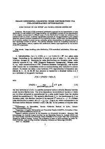
Figure 1. From left to right: sectorial structure of the anisotropic neighborhood achieved by combining a number of adaptive-scale directional windows; some of these windows selected by the ICI for the noisy Lena and Cameraman images; ˜x+ determined by the anisotropic LPA-ICI a detail of the noisy Cameraman showing an adaptive-shape neighborhood U procedure, and the image intensity corresponding to this region before and after hard-thresholding in SA-DCT domain.
which this e!ciency depends are also the primary characteristics sought for any transform-domain denoising algorithm. In this sense, the SA-DCT features a remarkable potential not only for video compression applications, but also for image and video denoising. However, this potential has been apparently ignored by the image denoising and restoration community. While this indi�erence may seem rather surprising, there are sound reasons that can justify it. The shape-adaptive coding of noise-free video objects always assumes that the boundary of these objects is known. This information can be obtained either from a-priori knowledge (e.g. motion estimation, chroma keying, layered structure), or it can be estimated from the data with one of the many automated segmentation algorithms suitable for this purpose. On the contrary, obtaining an accurate and robust segmentation of noisy data constitutes an extremely more complex task than the region-oriented coding itself. Unlike in MPEG-4 video coding, such a segmentation cannot be reasonably assumed to be known a-priori. This very aspect may be identified as the principal reason why the SA-DCT had not been used for the restoration of noisy images. A breakthrough in the use of SA-DCT for image filtering was reported by the authors in8. An image denoising algorithm was proposed which exploits the anisotropic LPA-ICI technique6, 16, in order to obtain — directly from the noisy data — an appropriate shape on which to apply the shape-adaptive transform. In this paper we further develop the approach and extend it to image restoration, proposing an image deblurring algorithm based on adaptive regularized deconvolution in overcomplete SA-DCT domain. Furthermore, the use of Gilge’s “shape-adapted” DCT is considered as an alternative to the faster Sikora’s SA-DCT. E!cient implementations based on this more complex transform are presented. The paper is organized as follows: first, we recall the main points of the anisotropic LPA-ICI technique and present various aspects of the shape-adaptive DCT transform; the developed LPA-ICI-driven SA-DCT denoising algorithm is then introduced, followed by its extension for image deblurring; we conclude with a number of experimental results that demonstrate the advanced performance of the proposed algorithms.
2. OBSERVATION MODEL AND NOTATION Let us introduce the considered observation model and some notation. First, we consider noisy observations z of the form z (x) = y (x) + � (x) , x 5 X, (1) � � where y is the original image, � (x) � N 0, �2 is white Gaussian noise, x is a spatial variable belonging to the image domain X � Z2 . Given a function f : X $ R, a subset U � X, and a function g : U $ R, we denote by f|U : U $ R the restriction of f on U , f|U (x) = f (x) ;x 5 U, and by g |X : X $ R the zero-extension of � � g to X, g |X |U = g and g |X (x) = 0 ;x 5 X \ U. The characteristic (indicator) function of U is defined as "U = 1|U |X . We denote by |U | the cardinality (i.e. the number of its elements) of U.
3. ANISOTROPIC LPA-ICI The approach is based on the Intersection of Confidence Intervals (ICI) rule, a method originally developed for pointwise adaptive estimation of 1D signals13, 15. The idea has been generalized for 2D image processing, where adaptive-size quadrant windows have been used17. Significant improvement of this approach has been
SPIE-IS&T/ Vol. 6064 60640N-2
mean subtraction
� �$
SA-DCT
hard-thresholding
inverse SA-DCT
� �$
� �$
� �$
mean addition
� �$
Figure 2. Hard-thresholding in SA-DCT domain. The image data on an arbitrarily shaped region is subtracted of its mean. The zero-mean data is then transformed and thresholded. After inverse transformation, the mean is added back.
achieved on the basis of anisotropic directional estimation6, 16. Multidirectional sectorial-neighborhood estimates are calculated for every point and the ICI rule is exploited for the adaptive selection of the size of each sector. Thus, the estimator is anisotropic and the shape of its support adapts to the structures present in the image. In Figure 1 we show some examples of these anisotropic neighborhoods for the Lena and Cameraman images. The developed anisotropic estimates are highly sensitive with respect to change-points, and allow to reveal fine elements of images from noisy observations. Let us present the overall method in more detail. For every specified direction �k , k = 1, . . . , K, a varyingscale family of directional-LPA (local polynomial approximation) convolution kernels16 {gh,�k }h5H is used to obtain a corresponding set of directional varying-scale estimates {ˆ yh,�k }h5H , yˆh,�k = z gh,�k , h 5 H. These estimates are then compared according to the ICI rule13, 15, and as a result an adaptive scale h+ (x, �k ) 5 H is defined for every x 5 X and for every direction �k . The corresponding adaptive-scale estimates yˆh+ (x,�k ),�k (x) are then “fused” together in an adaptive convex combination6, 16 in order to yield the final anisotropic LPA-ICI estimate. However, in this paper we are not interested in this anisotropic estimate. Instead, we consider only the adaptive neighborhood Ux+ , constructed as the union of the supports of the directional adaptive-scale kernels V gh+ (x,�k ),�k , Ux+ = K k=1 supp gh+ (x,� k ),� k , which we use as the support for a shape-adaptive transform. Observe that, being convolution kernels, the LPA kernels gh,�k are always “centered” at the origin, therefore Ux+ is a neighborhood of the origin. The actual adaptive neighborhood of x, which contains the observations that are ˜x+ = {v 5 X : (x � v) 5 Ux+ }. The neighborhoods shown in Figure 1 are in fact used for estimation, is instead U + ˜ examples of Ux for a few points x 5 X. Let us remark that there is a substantial di�erence between image segmentation, in which the image is decomposed in a limited number (� |X|) of non-overlapping subsets (image segments), and the anisotropic ˜x+ of x. In particular, because of the LPA-ICI, which for every x 5 X provides an adaptive neighborhood U nonparametric nature of the procedure, neighborhoods corresponding to adjacent points do usually overlap.
4. SHAPE-ADAPTIVE DCT 29, 31
The SA-DCT is computed by cascaded application of one dimensional varying-length DCT transforms first on the rows and then on the columns that constitute the considered region. Several improvements over its original definition have been proposed. In this paper, we concentrate only on the most significant19, which concern with the normalization of the transform and with the subtraction of the mean and which have a fundamental impact on the use of the SA-DCT for image filtering.
4.1. Orthonormal Shape-Adaptive DCT The normalization of the SA-DCT is obtained by normalization of the individual one-dimensional transforms that are used for transforming the rows and the columns. In terms of their basis elements, they are defined as: � � s s 1D-DCT , m, n = 0, . . . , L�1, c0 = 1/L, cm = 2/L, m > 0. #L,m (n) = cm cos �m(2n+1) (2) 2L Here L stands for the length of the row or column to be transformed. The normalization in (2) is indeed the most natural choice, since in this way all the transforms used are orthonormal and the corresponding matrices belong to the orthogonal group. Therefore, the SA-DCT — which can be obtained by composing two orthogonal matrices — is itself an orthonormal transform. A di�erent normalization of the 1D transforms wouldsproduce, on an arbitrary shape, a 2D transform that is non-orthogonal (for example as in29, 31, where c0 = 2/L and cm = 2/L for m > 0).
SPIE-IS&T/ Vol. 6064 60640N-3
Figure 3. Fast implementation of the LPA-ICI anisotropic neighborhoods. “Linewise”one-dimensional directional LPA kernels are used for 8 directions. The anisotropic neighborhood Ux+ is constructed as the polygonal hull of the adaptive˜x+ used for SA-DCT filtering of the noisy scale kernels’ supports (left). Some examples of the anisotropic neighborhoods U + Cameraman image (right), �=25. Only the adaptive scales h are needed to construct the neighborhoods. The corresponding Anisotropic LPA-ICI SA-DCT hard-thresholding estimate yˆ (7) and Wiener estimate yˆw i (12), and Gilge’s “shapeadapted” DCT Wiener estimate (PSNR=28.87, 29.10 dB, and 29.22 dB, respectively). In all the examples h=1,2,3,5,7,9.
Let us denote by TU : U $ V U the orthonormal SA-DCT transform obtained for a region U � X, where U = {f : U $ R} and V U = {* : VU $ R} are function spaces and VU � Z2 indicates the domain of the transform coe!cients. Let TU�1 : V U $ U be the inverse transform of TU . We indicate the thresholding (or quantization) operator � as � .� Thus, ��� the SA-DCT-domain processing of the observations z on a region U can be �1
T z , yˆU : U $ R. From the orthonormality of T and the model (1) follows that = T written as y ˆ U � U� U |U � � TU z|U = TU y|U + �¯, where �¯ = TU (� |U ) is again Gaussian white noise with variance �2 and zero mean.
4.2. Mean subtraction There is, however, an adverse consequence of the normalization (2). Even if the signal restricted to the shape z|U is constant, the reconstructed yˆU is usually non-constant. In19 this behavior is termed as “mean weighting defect”, and it is proposed there to attenuate its impact by applying the orthonormal SA-DCT on the zero-mean data which is obtained by subtracting from the initial data z its mean. After the inversion, the mean is added back to the reconstructed signal yˆU : U $ R: � � � ��� + mU (z) , (3) yˆU = TU�1 TU z|U � mU (z) 1 S where mU (z) = |U| x5U z (x) is the mean of z on U . Although this operation — which is termed “DC separation” — is not fully justified from the approximation theory standpoint (because mU (z) is calculated from the noisy data, and by subtracting it the noise in the coe!cients is no longer white), it produces visually superior results without a�ecting to the objective restoration performance. An illustration of the SA-DCT domain hard-thresholding, performed according to (3) is given in Figure 2.
5. ANISOTROPIC LPA-ICI -DRIVEN SA-DCT DENOISING ˜x+ defined by the LPA-ICI as supports for the SA-DCT, as shown We use the anisotropic adaptive neighborhoods U in Figure 1. In this way, we ensure that data are represented sparsely in the transform domain, significantly improving the e�ectiveness of thresholding. In practice, we do not need a variety of di�erent shapes as broad as in the examples of Figure 1 and a much simplified neighborhood structure is used in our implementation. Narrow one-dimensional “linewise” directional LPA kernels {gh,�k }h5{1,2,3,5,7,9} are used for K = 8 directions, and after the ICI-based selection of 8 the adaptive-scales {h+ (x, �k )}k=1 the neighborhood Ux+ is the octagon constructed as the polygonal hull of 8 � supp gh+ (x,�k ),�k k=1 . Such neighborhoods are shown in Figure 3. Although the supports obtained in this way have relatively simple shapes when compared to the more general examples of Figure 1, we found that this is not a significant restriction. On the contrary, a more regular boundary of the transform’s support usually improves the e!ciency of the SA-DCT1.
SPIE-IS&T/ Vol. 6064 60640N-4
5.1. Local estimates ˜x+ $ R of the signal y by thresholding in SA-DCT For every point x 5 X, we construct a local estimate yˆU˜x+ : U domain as in (3), � � � ���
x TU˜x+ z|U˜x+ � mU˜x+ (z) + mU˜x+ (z) , (4) yˆU˜x+ = TU˜�1 + x
where x is a hard-thresholding operator based on the threshold t ˜x+| + 1. � 2 ln |U An estimate of the variance
� ¯ 2yˆ + ˜ U x
˜ + , is given in the form of yˆU˜x+ , calculated as mean on U x � � 2 2 har ˜ � ¯ yˆ ˜ + = � 1 + Nx / |Ux+| ,
(5)
(6)
Ux
where Nxhar is the number of non-zero coe!cients after thresholding (which corresponds to the number of SADCT harmonics used for reconstruction) and the unit addend accounts for the addition of the mean after the inversion of the transform. Since the anisotropic neighborhoods corresponding to nearby points are usually overlapping, and since the ˜x+ , the overall approach is obviously overcomplete. SA-DCT is a complete basis for an individual support U
5.2. Global estimate as aggregation of local estimates In order to obtain a single global estimate yˆ : X $ R defined on the whole image domain, all the local estimates (4) are averaged together using adaptive weights wx 5 R in the following convex combination: S ˆU˜x+ |X x5X wx y . (7) yˆ = S ˜x+ x5X wx "U It is a standard approach to use weights wx that are inversely proportional to the mean variance (6) of yˆU˜x+ . As shown in14 for the case of sliding 8×8 block DCT denoising, such a simple weighting enables to attain the same performance achievable with much more involved models of the blocks’ statistics. However, this simple approach is inadequate when instead of fixed-size blocks one is considering adaptive regions with arbitrary shape and size. In particular, not only the size of the regions may vary, but also the number of overlapping shapes may be di�erent for di�erent points. If the inverse of the average variances are used as weights, it can be observed that when regions of significantly di�erent sizes overlap (this may happen along edges or transitions), then the local estimates corresponding to larger regions will inevitably “submerge” the finer details restored by smaller regions. We found experimentally that in such cases crucial compensation of these oversmoothing e�ects can be obtained by dividing the weights by the square of the size of the support, and we define wx as � ¯ �2 y ˆU 1 ˜+ wx = +x2 = . (8) har ˜x+| ˜ (1 + Nx ) |U |Ux | Let us observe that in areas where the size of the adaptive neighborhood is nearly constant (e.g. within smooth parts of the image) the weights (8) are inversely proportional to the mean variances of the corresponding local ¯ �2 estimates, wx 2 � yˆ + . Thus, we can use the weights (8) for such areas also. ˜ U x
5.3. Wiener filtering in SA-DCT domain Using the same approach as for thresholding, we introduce an empirical Wiener filter in the SA-DCT domain. It assumes that an estimate yˆ of y is known (in practice, we obtain this estimate using the above thresholding ˜x+ ) technique). For every x 5 X, let *yˆ,x : VU˜x+ $ R and *z,x : VU˜x+ $ R be — respectively — the SA-DCT (on U coe!cients of yˆ and z, where the mean mU˜x+ (z) is subtracted from the both before applying the transform: � � � � *yˆ,x = TU˜x+ yˆ|U˜x+ � mU˜x+ (z) , *z,x = TU˜x+ z|U˜x+ � mU˜x+ (z) . (9)
SPIE-IS&T/ Vol. 6064 60640N-5
wi The local Wiener estimate yˆU ˜ + is defined as
� � �1 wi yˆU ˜x+ (z) , ˜x+ = TU ˜ + $x *z,x + 'x mU
x
(10)
x
where $x 5 V U and 'x 5 R are, respectively, the Wiener attenuation factors for the SA-DCT coe!cients and for the subtracted mean value, m2U˜ + (ˆ y) *2yˆ,x x , ' = . (11) $x = 2 x 2 2 *yˆ,x + � mU˜ + (ˆ y) + �2 x
The global estimate yˆwi can be obtained analogously as in (7), using the convex combination with the adaptive weights wxwi : S wi wi |X ˆU˜ + 1 x5X wx y wi x , wxwi = . (12) yˆ = S S wi 2 ˜x+| ('x + V + $ 2x ) |U ˜x+ x5X wx "U Similarly to (8), the term '2x + wi yˆU ˜x+ .
˜ U x
S
$2x VU ˜+
in the adaptive weights corresponds to an estimate of the variance of
x
5.4. Gilge’s “shape-adapted” DCT by orthogonalization The shape-adaptive DCT proposed by Sikora et al. can be implemented very e!ciently with a negligible computational overhead with respect to the usual separable 2D DCT on a rectangular support. However, for video-coding applications Gilge’s “shape-adapted” DCT11, 12 based on orthonormalization with respect to shape is known to achieve superior results than the approach by Sikora et al. It is considered30 as a kind of upper bound on the decorrelation ability of the faster method. Thus, if computational complexity is not of primary concern, Gilge’s method may be utilized as an alternative method to achieve further improvement in denoising. We remark that the implementation of such “shape-adapted” DCT is not trivial. If general enough shapes are allowed� , precalculation of all possible shape-adapted bases is not feasible because the resulting look-uptable would be huge. Hence, the orthogonalization must be performed “on-line”. There are two more problems. First, when restricting a basis to a region smaller than the initial domain of its elements, linear independence is certainly lost. This makes orthonormalization ill-posed. Second, the resulting shape-adapted orthonormal basis significantly depends on the order in which the initial elements are orthonormalized. In particular, since an increasing number of orthogonal complements are successively subtracted during the orthogonalization, the similarity (and thus the common decorrelating features) between the resulting orthonormal elements and the initial ones diminishes as the procedure progresses. The combination of these two problems can have a devastating impact, because the attempt to orthonormalize any linearly-dependent element results in a systematic introduction of amplified rounding-errors in all subsequent elements, which are thus distorted. A rather profound study of these problems is given in27, providing criteria for the pruning of the starting basis so to obtain a set of elements which are linearly independent on the smaller region. Unfortunately, such criteria do not fully apply to arbitrary-shaped regions and additional numerical tests for independence must be employed. In our implementation of Gilge’s “shape-adapted” DCT we rely on a QR-decomposition to perform the orthonormalization. In order to overcome the above di!culties, we use the criteria from27 to prune the starting rectangular DCT basis, sorted according to a zig-zag scan. Additionally, to make sure that no distorted elements ˜x+| columns of the orthogonal Q are eventually used for the shape-adapted basis, we retain only the first Nx � |U matrix for which the magnitude of the corresponding diagonal entry of the upper-triangular matrix R exceeds ˜x+|, then the resulting set of generators is obviously not complete. However, a predefined threshold. If Nx < |U from the practical point of view it is still rich-enough to represent most considered signals which — thanks to the LPA-ICI-driven adaptive support — enjoy a particularly sparse decomposition. Let us remark that since the same shape-adapted basis is used for processing all neighborhoods which share the same shape, the above orthonormalization procedure needs to be performed only once for each unique shape. We process neighborhoods with identical shape one after another, simply by following the lexicographic order W In our implementation — for example — despite the rather simplified neighborhood structure (based on |H| = 6 scales and K = 8 directions, as described in Figure 3), a total of 68 = 1679616 di�erent shapes are possible.
SPIE-IS&T/ Vol. 6064 60640N-6
Figure 4. Fragment from the blurred and noisy observation of the Cameraman image (Exp. 1) (left). Flowchart of the SADCT regularized Wiener inverse algorithm (center). In the upper part of the flowchart a deblurred estimate yˆR I is obtained by combining the regularized-inversion (RI) operator with the SA-DCT-domain hard-thresholding. This estimate is used as reference estimate for the regularized-Wiener stage of the lower part of the flowchart, where a regularized Wiener inverse (RWI) operator is combined with Wiener filtering in SA-DCT domain. The intermediate yˆR I and the final yˆRW I estimates are respectively obtained by averaging with adaptive weights (represented as “P”) the local SA-DCT estimates yˆxR I and yˆxRW I , whose supports are defined by the anisotropic LPA-ICI technique on the regularized inverse z R I and regularized Wiener inverse z RW I . The deblurred RWI estimate yˆRW I of the Cameraman image using Gilge’s “shape-adapted” DCT (ISNR=8.58dB) (right).
˜x+ . Therefore only a single shape-adapted induced by the directional adaptive scales h+ (x, � k ) which define U basis needs to be kept in memory. Since the number of distinct shapes found in a image is usually much less than the total number of pixels, the computational drawback of Gilge’s against Sikora’s method is mostly due to ˜x+| matrix, whereas the latter the fact that the former transform is performed as multiplication against a Nx ×|U uses transformation by rows and by columns, just like a separable transform. The denoising algorithm described in Sections 5.1-5.3 is valid also if Gilge’s “shape-adapted” DCT is used instead of the SA-DCT. However, since these shape-adapted bases have indeed a DC term which truly corresponds to a constant basis element, there is no mean-weighting defect (as described in Section 4.2) and the subtraction of the mean is not necessary. It means that for Gilge’s “shape-adapted” DCT, formulas (3-12) can take a simpler y ) are replaced by zeros. form, where the mean terms mU˜x+ (z) and mU˜x+ (ˆ
6. SA-DCT REGULARIZED DECONVOLUTION In this section we extend the above SA-DCT denoising approach to image deblurring. First, let us generalize the observation model (1) given in Section 2, introducing an optical blurring into the observation process. This distortion is commonly modeled by the convolution y v of the true image y with the point-spread function (PSF) v of the optical system. Thus, we wish to recover y from the blurred and noisy observations z (x) = (v y) (x) + � (x) , x 5 X. (13) In the frequency domain the above equation becomes Z = Y V +��˜, where capital letters are used for the discrete � Fourier transform of the corresponding variables and �˜ (·) � N 0, � 2 . It is assumed that the PSF v is known. Note that the observation model (1) is a particular case of (13) where v is a Dirac function.
The proposed deblurring algorithm is based on the anisotropic regularized inverse (RI) and regularized Wiener inverse (RWI) LPA-ICI deconvolution scheme developed in16, 18. The same deconvolution technique has also been used for inverse halftoning7 and Poissonian deblurring9. The idea of the proposed SA-DCT domain deblurring is to combine the SA-DCT transform with the regularized inversion operators, using the adaptive supports defined by the anisotropic LPA-ICI regularized deconvolution. The flowchart of the overall deblurring algorithm is shown in Figure 4.
6.1. Regularized inverse The regularized inverse (RI) z R I is computed in the frequency domain as V z R I = F �1 (T R I Z) , T RI = , |V |2 + %21
SPIE-IS&T/ Vol. 6064 60640N-7
(14)
where T R I is a (Tichonov) regularized-inversion operator, %1 > 0 is a regularization parameter, and V is the complex conjugate of V . In what follows we make explicit use of the impulse response tR I of the regularizedinversion operator, tR I = F �1 (T R I ).
6.2. Adaptive anisotropic transform support K
The anisotropic neighborhood Ux+ is constructed from the adaptive scales {h+ (x, �k )}k=1 obtained from to the following procedure. The LPA is performed in the spatial domain as a convolution of the regularized inverse z R I RI against the LPA kernel gh,�k , yˆh,� = z R I gh,�k , for each specified direction �k , k = 1, . . . , K, and for every k RI }h5H obtained for each � are fed (together with their scale h 5 H. All the varying-scale LPA estimates {ˆ yh,� k R I RI = � nt gh,� n2 }h5H ) into the ICI algorithm, which selects the pointwise-adaptive standard deviations {� yˆh,� scale h+ (x, � k ). The adaptive scale selection is done independently for each direction � k .
6.3. SA-DCT deblurring A non-linear adaptive deblurring operator is obtained by combining the regularized inversion (14) with the shape-adaptive DCT domain shrinkage. While formally it is enough to replace z by z R I in (4), several further modifications to the basic denoising procedure of Section 5 are required in order to properly take into account the initial regularized inversion. The principal di�erence arises from the fact that, because of the blur inversion (14), the noise in z R I is colored. Therefore the noise variance in the transform domain is not constant and instead can vary significantly from a coe!cient to the other. Consequently, the threshold (5) cannot be used in order to determine which coe!cients should be used for the reconstruction of the deblurred estimate. 6.3.1. Thresholding with adaptive variance in transform domain We consider the individual variance of the transform coe!cients *zR I,x = TU˜x+ (z|RU˜I + � mU˜x+ (z R I )). Let i 5 VU˜x+ x
(i) ˜x+ $ R, which are defined implicitly be coordinates in SA-DCT domain. The SA-DCT basis functions #U˜ + : U x by the cascaded row-column structure of the SA-DCT, can be obtained explicitly by inverse transformation of (i) the standard basis {ei }i5V + as # U˜ + = TU˜�1 ˜x+ . + (ei ), i 5 VU ˜ U x
x
x
Neglecting the mean subtraction (“DC separation”), the variance � 2*zR I,x (i) of the i-th transform coe!cient *zR I,x (i) is (i)
(i)
x
x
� 2*zR I,x (i) = � 2 n tR I #U˜ + |X n22 = �2 n T R I F(#U˜ + |X ) n22 .
(15)
The appropriate threshold level for each transform coe!cient is obtained by replacing the coe!cient-invariant � in the threshold (5) with the varying standard deviation �*zR I,x : VU˜x+ $ R. In this way, we realize an adaptive hard-thresholding rule for the joint deblurring and filtering in SA-DCT domain. RI Analogously to (4), a local deblurred estimate yˆU ˜x+ is obtained by inverse transformation of the thresholded coe!cients.
6.3.2. Adaptive weights and global estimate RI Just as in Section 5.2, in order to obtain a global estimate yˆR I : X $ R all the local estimates yˆU ˜x+ are averaged RI together using adaptive weights wx 5 R in a convex combination analogous to (7). However, because of the di�erent variances of the coe!cients used in the reconstruction, the adaptive weights are defined by a di�erent formula. Ignoring the correlation between the noise in the transform domain, the corresponding expression of (8) for deblurring is 1 � wxR I = � S ˜x+| �2m + �2* (j) |U zR I,x
j5S
zR I,x
where S � VU˜x+ indicates the coe!cients which are non-zero after thresholding and �2mzR I,x = �2 ˜x+| |U
n T R I F("U˜x+ ) n22 is an extra term which accounts for the “DC separation”.
SPIE-IS&T/ Vol. 6064 60640N-8
�2 ˜x+| |U
n tR I "U˜x+ n22 =
Figure 5. A fragment of Lena. From left to right: original, noisy observation (�=25, PSNR=20.18dB), BLS-GSM estimate28 (PSNR=31.69dB), and the proposed Anisotropic LPA-ICI-driven SA-DCT and Gilge’s “shape-adapted” DCT Wiener estimates (PSNR=31.66 and 31.76 dB, respectively).
6.4. Regularized Wiener inverse The regularized Wiener inverse (RWI) z RW I is computed as V |Y |2 , (16) |V Y |2 + %22 �2 where %2 > 0 is a regularization parameter. Since the spectrum |Y |2 of the true image is unknown, the estimate yˆR I from the RI stage is used quite naturally as a “pilot” estimate in the Wiener filtering. It means that |Y |2 in (16) is replaced by |Yˆ R I |2 . ˜ + are defined by the anisotropic LPA-ICI technique Analogously to Section 6.2, the adaptive neighborhoods U x RW I applied to z . z RW I = F �1 (T RW I Z) ,
T RW I =
On these neighborhoods we perform empirical Wiener filtering in SA-DCT domain in a fashion similar to Section 5.3, where the attenuation coe!cients for the filter (10) are m2U˜ + (ˆ yR I ) *2yˆR I,x x $x = 2 , ' = . x *yˆR I,x + �2*zRW I,x m2U˜ + (ˆ yR I ) + � 2mzRW I,x x
The variances �2*zRW I ,x and � 2mzRW I ,x are defined as in (15), but using the regularized Wiener inverse operator T RW I or its impulse response tRW I = F �1(T RW I ) instead of T R I or tR I , respectively. These variances are also used to define the adaptive weights used for the aggregation of the local estimates: 1 � wxRW I = � . S ˜x+| '2x � 2mzRW I,x + V + $ 2x �2*zRW I,x |U ˜ U x
6.5. Fast computation of coe!cients’ variance The calculation of the variance of the transform coe!cients as in (15) is a rather computationally intense procedure. In order to reduce complexity to an acceptable level, it is necessary to employ some approximations. Our implementation of (15) is based on processing in an undersampled (“coarse”) FFT domain of size 32×32. h a 32×32 domain, and by L a decimator with prefiltering, we Denoting by Fh the corresponding transform, by X have the following approximation of the variance of the i-th transform coe!cient *zR I,x (i): � � h (i)+ |Xh ) )2 � . �2* (i) * �2 � L{(F(tR I ))2 }(F(# (17) zR I,x
˜x U
1
An obvious modification to the above formula allows to compute approximations of the variances �2*zRW I,x .
Such approximations have a significant impact on the computational performance of the algorithm. The current Mdwode implementation can process a 512×512 image in about a minute. This includes RI and RWI stages, comprehensive of LPA-ICI and transform-domain filtering. If (15) would be used instead of the approximate (17), the processing time would be of a few hours, without any noticeable improvement in the restoration quality.
SPIE-IS&T/ Vol. 6064 60640N-9
Method
�
Anis. LPA-ICI + Gilge’s “SA”-DCT Anis. LPA-ICI + SA-DCT BLS-GSM (Portilla et al.) 28 Exemplar-based (Kervrann and Boulanger) 21 MGGD (Cho and Bui) 2 Recursive Anisotropic LPA-ICI 6, 10
Lena 512×512 15 20 25 34.00 33.86 33.90 33.70 33.70 32.72
32.75 32.62 32.66 32.64 32.46 31.44
31.76 31.66 31.69 31.73 31.48 30.43
Boats 512×512 15 20 25 31.85 31.79 31.70 31.44 31.46 30.87
30.54 30.49 30.38 30.12 30.14 29.58
29.52 29.47 29.37 29.20 29.12 28.58
Peppers 256×256 15 20 25 32.62 32.44 31.74 32.13 — 31.78
31.19 31.04 30.31 30.59 — 30.30
30.07 29.93 29.21 29.73 — 29.16
House 256×256 15 20 25 34.26 34.14 33.63 34.08 — 33.18
33.01 32.92 32.39 32.90 — 31.82
32.00 31.92 31.40 32.22 — 30.73
Table 1. PSNR (dB) comparison table for the denoising of the Lena, Boats, Peppers, and House test images with di�erent levels of Gaussian noise.
Figure 6. Fragments of the Wiener estimates of the Boats, Peppers, and House images, �=25. For each test image are shown the two di�erent final estimates, one based on the low-complexity SA-DCT (left), the other based on Gilge’s “shape-adapted” DCT. From these images it can be seen that the visual quality of the two methods is essentially the same.
6.6. “Shape-adapted” DCT deblurring The described algorithm can be used also with Gilge’s “shape-adapted” DCT, provided that simple modifications, anologous to those described in Section 5.4, are made. Let us remark that because of the need to go through the explicit expression of each one of the SA-DCT basis (i) elements #U˜ + , i 5 VU˜x+ , the computational advantage of the Sikora’s SA-DCT over Gilge’s “shape-adapted” DCT x is substantially reduced. In fact, our implementations of the proposed deblurring algorithm based on Gilge’s “shape-adapted” DCT and on the lower-complexity SA-DCT perform in about the same time.
7. EXPERIMENTS We conclude the paper with a few experimental results which demonstrate state-of-the-art performance of the developed algorithms. Further simulation results and the Mdwode software which has been used to perform the presented experiments are available at http://www.cs.tut.fi/~foi/SA-DCT/. The results are presented for both the SA-DCT and Gilge’s “shape-adapted” DCT, using the same transform for the thresholding and Wiener filtering stages of the denoising and deblurring algorithms.
7.1. Denoising In Table 1 we compare our results against those reported by other authors. In terms of PSNR, the results of both our estimates are high, often outperforming all other methods. We emphasize the outstanding preservation of sharp details which we demonstrate in Figures 5 and 6, while almost no visible artifacts are present. Other transform-based estimates, such as those from28, often display noticeable overshootings on the edges and unpleasant spurious oscillations. These artifacts, which are characteristic of all oscillatory transforms (including the SA-DCT), do not appear in our estimates thanks to the adaptive selection of the transform support. Let us note that Gilge’s method provides only a marginal improvement over the lower-complexity SA-DCT, thus the latter is a more likely choice for practical implementations.
SPIE-IS&T/ Vol. 6064 60640N-10
Method
Experiment
Anis. LPA-ICI RI-RWI + Gilge’s “SA”-DCT Anis. LPA-ICI RI-RWI + SA-DCT Anisotropic LPA-ICI RI-RWI 10, 16 BOA (Figueiredo and Nowak) 5 GEM (Dias)3 Segmentation-based Regularization (M ignotte) 24 EM (Figueiredo and Nowak) 4 ForWaRD (Neelamani et al.) 25
1
2
3
8.58 8.48 8.29 8.16 8.10 8.04 7.59 7.30
8.29 8.21 7.82 7.46 7.47 7.23 6.93 6.75
6.34 6.26 5.98 5.24 5.17
4
4.55 4.47 3.90 2.84 2.73 — 1.34 4.88 2.94 5.07 2.98
Exp. Image, Point-Spread Function v , noise 1 2 3 4
Cameraman 256×256 BSNR=40dB 9×9 boxcar uniform v (�2 *0.308) Cameraman 256×256 �2 =2 2 2 v (x 1 ,x 2 )=1/(1+x 1 +x 2 ), x 1 ,x 2 =-7,...,7 Cameraman 256×256 �2 =8 2 2 v (x 1 ,x 2 )=1/(1+x 1 +x 2 ), x 1 ,x 2 =-7,...,7 Lena 512×512 �2 =49 T v =[1,4,6,4,1] [1,4,6,4,1]/256
Table 2. Left: ISNR (dB) of the proposed deblurring algorithm and of other state-of-the-art methods for four standard experiments. Right: description of the observation parameters for the four experiments.
Figure 7. Fragments of the observations z and estimates yˆRW I for the deblurring experiments 3 and 4 (ISNR=6.34 and 4.55 dB, respectively) .
7.2. Deblurring In order to evaluate the restoration ability of the proposed deblurring algorithm, we consider the standard set of four blurred and noisy observations which has been used by many other authors. Table 1 presents the description of the observations’ parameters and the improvement-in-SNR (ISNR) results for these four experiments. Figures 4 and 7 show details of the observations and the corresponding restored images. Similarly to denoising, both the objective and subjective quality of our estimates are high, outperforming the best methods known to date.
REFERENCES 1. Bi, M., S.H. Ong, and Y.H. Ang, “Comment on Shape-Adaptive DCT for generic coding of video”, IEEE Trans. Circuits and Systems for Video Technology, vol. 6, no. 6, pp. 686-688, December 1996. 2. Cho, D., and T.D. Bui, “Multivariate statistical modeling for image denoising using wavelet transforms”, Signal Processing: Image Communications, vol. 20, no. 1, pp. 77-89, January 2005. 3. Dias, J.M.B., “Fast GEM wavelet-based image deconvolution algorithm”, Proc. Int. Conf. Image Process., ICIP 2003, vol. 2, 2003. 4. Figueiredo, M.A.T., and R.D. Nowak, “An EM algorithm for wavelet-based image restoration”, IEEE Trans. Image Process., vol. 12, no. 8, pp. 906-916, 2003. 5. Figueiredo, M.A.T., and R.D. Nowak, “A bound optimization approach to wavelet-based image deconvolution”, Proc. IEEE 2005 Int. Conf. Image Process., ICIP 2005, vol. 2, pp. 782-785, Genova, September 2005. 6. Foi, A., V. Katkovnik, K. Egiazarian, and J. Astola, “A novel anisotropic local polynomial estimator based on directional multiscale optimizations”, Proc. 6th IMA Int. Conf. Math. Signal Process., pp. 79-82, Cirencester, 2004. 7. Foi, A., V. Katkovnik, K. Egiazarian, and J. Astola, “Inverse halftoning based on the anisotropic LPA-ICI deconvolution”, Proc. 2004 Int. TICSP Workshop Spectral Meth. Multirate Signal Process., SMMSP 2004, pp. 49-56, Vienna, September 2004. 8. Foi, A., V. Katkovnik, and K. Egiazarian, “Pointwise shape-adaptive DCT as an overcomplete denoising tool”, Proc. 2005 Int. TICSP Workshop Spectral Meth. Multirate Signal Process., SMMSP 2005, pp. 164-170, Riga, June 2005. 9. Foi, A., S. Alenius, M. Trimeche, V. Katkovnik, and K. Egiazarian, “A spatially adaptive Poissonian image deblurring”, Proc. IEEE 2005 Int. Conf. Image Process., ICIP 2005, pp. 925-928, Genova, September 2005.
SPIE-IS&T/ Vol. 6064 60640N-11
10. Foi, A., D. Paliy, V. Katkovnik, and K. Egiazarian, “Anisotropic nonparametric image restoration demobox” (Mdwode software), LASIP (Local Approximations in Signal and Image Processing) Project, http://www.cs.tut.fi/~lasip/ , 2005. 11. Gilge, M., T. Engelhardt, and R. Mehlan, “Coding of arbitrarily shaped image segments based on a generalized orthogonal transform”, Signal Processing: Image Communication, vol. 1, no. 2, pp. 153-180, October 1989. 12. Gilge, M., “Region oriented transform coding (ROTC) of images”, Proc. of Int. Conf. on Acoustics, Speech, and Signal Processing, ICASSP-90, Albuquerque, USA, vol. 4, pp. 2245-2248, April 1990. 13. Goldenshluger, A., and A. Nemirovski, “On spatial adaptive estimation of nonparametric regression”, Math. Meth. Statistics, vol. 6, pp. 135-170, 1997. 14. Guleryuz, O.G., “Weighted overcomplete denoising”, Proc. Asilomar Conference on Signals and Systems, Pacific Grove, CA, November 2003. 15. Katkovnik V., “A new method for varying adaptive bandwidth selection”, IEEE Trans. Signal Process., vol. 47, no. 9, pp. 2567-2571, 1999. 16. Katkovnik, V., A. Foi, K. Egiazarian, and J. Astola, “Directional varying scale approximations for anisotropic signal processing”, Proc. XII European Signal Process. Conf., EUSIPCO 2004, pp. 101-104, Vienna, September 2004. 17. Katkovnik, V., K. Egiazarian, and J. Astola, “Adaptive window size image de-noising based on intersection of confidence intervals (ICI) rule”, J. of Math. Imaging and Vision, vol. 16, no. 3, pp. 223-235, 2002. 18. Katkovnik, V., K. Egiazarian, and J. Astola, “A spatially adaptive nonparametric regression image deblurring”, IEEE Trans. on Image Process., vol. 14, no. 10, pp. 1469-1478, October 2005. 19. Kau�, P., and K. Schuur, “Shape-adaptive DCT with block-based DC separation and �DC correction”, IEEE Transactions on Circuits and Systems for Video Technology, vol. 8, no. 3, pp. 237-242, 1998. 20. Kaup, A., and S. Panis, “On the performance of the shape adaptive DCT in object-based coding of motion compensated di�erence images”, Proc. of 1997 Picture Coding Symposium, pp. 653-657, 1997. 21. Kervrann, C., and J. Boulanger, “Local adaptivity to variable smoothness for exemplar-based image denoising and representation”, Research Report no. 5624, INRIA, July 2005. 22. Kinane, A., V. Muresan, and N. O’Connor, “Optimal adder-based hardware architecture for the DCT/SADCT”, Proc. SPIE Visual Comm. and Image Process. Conf., VCIP 2005, Beijing, China, 12-15 July 2005. 23. Koenen, R., “Overview of the MPEG-4 Standard”, ISO/IEC JTC1/SC29/WG11 Doc. N3536, July 2000. 24. Mignotte, M., “An adaptive segmentation-based regularization term for image restoration”, Proc 12th IEEE Int. Conf. Image Process., ICIP’05, vol. 1, pp. 901-904, Italy, Genova, September 2005. 25. Neelamani, R., H. Choi, and R. Baraniuk, “Forward: Fourier-wavelet regularized deconvolution for illconditioned systems”, IEEE Trans. Image Process., vol. 52, no. 2, 2004. 26. Ostermann, J., E.S. Jang, J. Shin, and T. Chen, “Coding of arbitrarily shaped video objects in MPEG-4”, Proc. Int. Conf. Image Process., ICIP 1997, pp. 496-499, 1997. 27. Philips, W., “Orthogonal base functions on a discrete two-dimensional region”, ELIS Technical Report DG 91-20, Dept. of Electronics and Inform. Syst., Universiteit Gent, Belgium, November 1993. 28. Portilla, J., V. Strela, M. Wainwright, and E.P. Simoncelli, “Image denoising using scale mixtures of Gaussians in the wavelet domain”, IEEE Trans. Image Process., vol. 12, no. 11, pp. 1338-1351, November 2003. 29. Sikora, T., “Low complexity shape-adaptive DCT for coding of arbitrarily shaped image segments”, Signal Processing: Image Communication, vol. 7, pp. 381-395, 1995. 30. Sikora, T., S. Bauer, and B. Makai, “E!ciency of shape-adaptive 2-D transforms for coding of arbitrarily shaped image segments,” IEEE Trans. on Circuits and Systems for Video Technology, vol. 5, no. 3, pp. 254-258, June 1995. 31. Sikora, T., and B. Makai, “Shape-adaptive DCT for generic coding of video”, IEEE Trans. on Circuits and Systems for Video Technology, vol. 5, no. 1, pp. 59-62, 1995.
SPIE-IS&T/ Vol. 6064 60640N-12