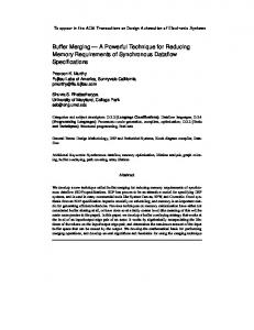
University of Maryland, College Park, MD, USA. Abstract. There has been a proliferation of block-diagram environ- ments for specifying and prototyping DSP ...
Proceedings of the Design, Automation and Test in Europe Conference, March 2000. Paris, France.
Shared Memory Implementations of Synchronous Dataflow Specifications
Praveen K. Murthy Angeles Design Systems, San Jose Ca, USA Shuvra S. Bhattacharyya University of Maryland, College Park, MD, USA
Abstract There has been a proliferation of block-diagram environments for specifying and prototyping DSP systems. These include tools from academia like Ptolemy [3], and GRAPE [7], and commercial tools like SPW from Cadence Design Systems, Cossap from Synopsys, and the HP ADS tool from HP. The block diagram languages used in these environments are usually based on dataflow semantics because various subsets of dataflow have proven to be good matches for expressing and modeling signal processing systems. In particular, synchronous dataflow (SDF)[8] has been found to be a particularly good match for expressing multirate signal processing systems. One of the key problems that arises during synthesis from an SDF specification is scheduling. Past work on scheduling [1] from SDF has focused on optimization of program memory and buffer memory. However, in [1], no attempt was made for overlaying or sharing buffers. In this paper, we formally tackle the problem of generating optimally compact schedules for SDF graphs, that also attempt to minimize buffering memory under the assumption that buffers will be shared. This will result in schedules whose data memory usage is drastically lower (upto 83%) than methods in the past have achieved.
1
Introduction
Block diagram environments are proving to be increasingly popular for developing DSP systems [1][7][14]. In a block-diagram environment, the user connects up various blocks drawn from a library to form the system of interest. For simulation, these blocks are typically written in a high level language like C++. For software synthesis, the technique typically used is that of threading: a schedule is generated, and the code generator steps through this schedule and substitutes the code for each actor that it encounters in the schedule. The code for the actor may be of two types: it may be the HLL code
itself (or behavioral HDL code), obtained from the actor in the simulation library, or it could be native assembly code. The overall code may now be compiled for the appropriate target. Since the first step in these synthesis flows is the scheduling of the block diagram, we consider in this paper scheduling strategies for minimizing memory usage, where we make use of the restricted control flow in the SDF specification model. In particular, we describe a technique for reducing buffering requirements in SDF graphs based on lifetime analysis and memory allocation heuristics for single appearance looped schedules. Lifetime analysis techniques for sharing memory are well known in a number of contexts. The first is for register allocation in traditional compilers; given a scheduled dataflow graph, register allocation techniques determine whether the variables in the graph can be shared by looking at their lifetimes. In the simplest form, this problem can be formulated as an interval graph coloring problem that has an elegant polynomial-time solution. However, the problem of scheduling the graph so that the overall register requirement is minimized is an NP-hard problem. Register allocation problems are made somewhat simpler because the variables in question all have the same size. The allocation problem becomes NP-complete if variables are of differing sizes, as for example, in allocating arrays of different sizes to memory. In [4], Fabri studies the more general problem of overlaying arrays and strings in imperative languages. She models array lifetimes as weighted interval graphs and uses coloring heuristics for generating memory allocations. She also studies transformation techniques for lowering the overall memory cost; these techniques attempt to minimize the lower and upper bounds on the extended chromatic number of the weighted interval graph. There are important differences between Fabri’s work and ours. Fabri considers general imperative language
code, and hence has to solve allocation problems for a more general class of interval graphs. We apply our techniques on SDF graphs, and because the SDF model of computation is restricted, the interval graphs in our problem have a more restricted structure, enabling us to use simpler allocation heuristics more effectively. The SDF model and SDF schedules present unique problems for deducing the liveness profiles, and thus the interval graphs, in an efficient manner; these techniques have not been presented or studied in any previous work. We show that for the important class of single appearance schedules, these deductions can be made in polynomial time in the size of the SDF graph. We present an optimization technique for reducing the extended chromatic number by performing loop fusion in a systematic manner; previous work has not addressed this relationship. While the loop fusion technique is applicable in a general setting as well, opportunities for doing it in a general setting do not arise as frequently and naturally as they do in an SDF setting; hence, it is a very effective technique here. For example, determining the applicability of loop fusion is undecidable in procedural languages; whereas exact analysis is decidable and tractable in our context. Finally, even though certain subsets of the techniques we present in this paper have been studied in the compilers community, to date they have not been used in block-diagram compilers. An additional contribution of this paper is to show that many of the techniques used in traditional compilers can be specialized and applied fruitfully in block diagram based DSP programming environments. In a synthesis tool called ATOMIUM, De Greef et al. have developed lifetime analysis and memory allocation techniques for single-assignment, static control-flow specifications that involve explicit looping constructs, such as for loops [6]. The class of specifications addressed by ATOMIUM exhibits less predictable array accessing behavior than the buffer access patterns that emerge from single appearance schedules. We exploit this increased predictability in our work using an innovative tree-based schedule representation. The techniques of ATOMIMUM provide efficient exact detection of inter-array lifetime conflicts only in a few restricted cases; in general, an exact analysis has prohibitive complexity [6]. In contrast, our techniques provide efficient (polynomial-time) and exact computation of lifetime interference information between any pair of SDF buffers (that is, between their address windows). Bhattacharyya developed a buffer sharing formulation in [2], using lifetime analysis and intersection graph construction, for arbitrary schedules (not necessarily SASs). Since non single appearance schedules can be of exponential length, lifetime analysis and intersection graph con-
struction has much higher complexity in the formulation of [2]. Also, in [2], buffer sharing is not allowed at the fine granularity that is allowed in this paper; for example, periodicity is not taken into account. Finally, no attempt is made in [2] to drive the scheduling algorithm in such a way that the total (shared) allocated memory is minimized. Ritz et. al. [14] give an enumerative approach to minimizing buffer memory that operates only on flat SASs since buffer memory reduction is tertiary to their goal of reducing code size and context-switch overhead (defined roughly as the rate at which the schedule switches between various actors). We do not take context-switch into account in our scheduling techniques because our primary concern is memory minimization as avoiding off-chip memory is often a bottleneck in embedded systems implementations. Sung et. al consider expanding the SAS to allow 2 or more appearances of some actors if the buffering memory can be reduced [15]. They also explore ways of combining procedure calls with inline code for cases where the block diagram contains multiple instances of the same basic actor (parametrized differently). Finally, our work is complementary to the ongoing work being done to improve compilers for DSPs [9] since the actor blocks themselves have to be compiled or handcoded in assembly language in block diagram synthesis environments. Our scheduling techniques make use of the restricted nature of the overall control flow; a general purpose compiler is often unable to exploit these system-level opportunities since it has no knowledge of the particular model of computation used for the specification.
2
Notation and background
Dataflow is a natural model of computation to use as the underlying model for a block-diagram language for designing DSP systems. The blocks in the language correspond to actors in a dataflow graph, and the connections correspond to directed edges between the actors. These edges not only represent communication channels, conceptually implemented as FIFO queues, but also establish precedence constraints. An actor fires in a dataflow graph by removing tokens from its input edges and producing tokens on its output edges. The stream of tokens produced this way corresponds naturally to a discrete time signal in a DSP system. In this paper, we consider a subset of dataflow called synchronous dataflow (SDF) [8]. In SDF, each actor produces and consumes a fixed number of tokens, and these numbers are known at compile time. Each edge has a fixed initial number of tokens, called delays. Fig. 1 shows a simple SDF graph. Each edge is annotated with the number of tokens produced (consumed) by
its source (sink) actor, and the “D” on the edge from actor A to actor B specifies a unit delay. Each unit of delay is implemented as an initial token on the edge. Given an SDF edge e , we denote the source actor, sink actor, and delay of e by src ( e ) , snk ( e ) , and del ( e ) . Also, prod ( e ) and cns ( e ) denote the number of tokens produced onto e by src ( e ) and consumed from e by snk ( e ) . A schedule is a sequence of actor firings. We compile an SDF graph by first constructing a valid schedule — a finite schedule that fires each actor at least once, does not deadlock, and produces no net change in the number of tokens queued on each edge. We represent the minimum number of times each actor must be fired in a valid schedule by a vector q G , indexed by the actors in G (we often suppress the subscript if G is understood). These minimum numbers of firings can be derived by finding the minimum positive integer solution to the balance equations for G , which specify that q must satisfy prod ( e )q ( src ( e ) ) = cns ( e )q ( snk ( e ) ) , for every edge e in G . The vector q , when it exists, is called the repetitions vector of G , and can be computed efficiently [1]. We define TNSE ( e ) to be the total number of samples exchanged on edge e by actor snk ( e ) ; i.e, TNSE ( e ) = q ( snk ( e ) ) ⋅ cns ( e ) .
3
Constructing memory-efficient loop structures
In [1], the concept and motivation behind single appearance schedules (SAS) was defined and shown to yield an optimally compact inline implementation of an SDF graph with regard to code size (neglecting the code size overhead associated with the loop control). A single appearance schedule is one where each actor appears only once when loop notation is used. Figure 2 shows an SDF graph, and valid schedules for it. The notation 2B represents the firing sequence BB . Similarly, 2B ( 2C ) represents the schedule loop with firing sequence BCCBCC .
A
D
2
1
B
3
1
C
Fig 1. Example of an SDF graph. (a)
A
20
10
B
20
10
C
Valid Schedules (b )
(1): ABCBCCC
(2): A(2 B(2 C))
(3): A(2 B)(4 C)
(4): A(2 BC)(2 C)
Fig 2. An example used to illustrate the interaction between scheduling SDF graphs and the memory requirements of the generated code.
We say that the iteration count of this loop is 2 , and the body of this loop is B ( 2C ) . Schedules 2 and 3 in figure 2 are SASs since actors A, B, C appear only once. An SAS like the third one in Figure 2(b) is called flat since it does not have any nested loops. In general, there can be exponentially many ways of nesting loops in a flat SAS Scheduling can also have a significant impact on the amount of memory required to implement the buffers on the edges in an SDF graph. For example, in Figure 2(b), the buffering requirements for the four schedules, assuming that one separate buffer is implemented for each edge, are 50, 40, 60, and 50 respectively.
4
Optimizing for buffer memory
The 2-dimensional design space involving code and data memory requirements of SDF specifications is extremely complex [1]. We give priority to code-size minimization over buffer memory minimization following the work in [1][10]. Hence, the problem we tackle is one of finding buffer-memory-optimal SAS, since this will give us the best schedule in terms of buffer-memory consumption amongst the schedules that have minimum code size. Following [1] and [10], we also concentrate on acyclic SDF graphs since algorithms for acyclic graphs can be used in the general SAS framework developed in [1]. In particular, the loose interdependence framework of [1] constructs an SAS for an arbitrary SDF graph by decomposing the SDF graph into strongly connected components recursively. At each step, the resulting acyclic component graph can be scheduled by any of these algorithms that operate on acyclic SDF graphs. If the SAS restriction is removed, significant reductions in buffer sizes can result, but at the expense of code size. The increase in code size will manifest itself even if inline code-generation is not used and subroutine calls are used instead. This is because the length of a non-SAS can be exponential in the size of the graph, and there could be exponentially many subroutine calls. For an acyclic SDF graph, any topological sort a b c… immediately leads to a valid flat SAS given by ( q ( a )a ) ( q ( b )b )… . Each such flat SAS leads to a set of SASs corresponding to different nesting orders. In [10] and [1], the buffering cost is defined as the sum of the buffer sizes on each edge, assuming that each buffer is implemented separately, without any sharing. With this cost function, a post-processing algorithm called dynamic programming post optimization (DPPO) is given that organizes a buffer-optimal nested looped schedule for any given flat SAS (i.e, performs loop fusion optimally on the flat SAS). Two heuristics are given for generating good topological orderings, called APGAN (Acyclic Pair-
In this paper, we use an alternative cost for implementing buffers. Our cost is based on sharing buffers based on their lifetimes. We tackle four issues to enable this optimization: a model for sharing buffers, an algorithm for performing loop fusion with the shared buffer cost as the objective function, deducing the buffer lifetimes from the graph and schedule efficiently, and effective allocation heuristics for sharing the buffers given a nested SAS.
5
R-Schedules and the Schedule Tree
As shown in [10], it is always possible to represent any single appearance schedule for an acyclic graph as ( iL S L ) ( iR SR )
(EQ 1)
where S L and S R are SASs for the subgraphs consisting of the actors in S L and in S R , and i L and i R are loop factors for iterating these schedules. In other words, the graph can be partitioned into a left subset and a right subset so that the schedule for the graph can be represented as in equation 1. SASs having this form of the loop hierarchy are called R-schedules [10].
1
1 A
2 B
T BC 2C
A
1 2B
6
The shared buffer model
Buffer sharing for looped schedules can be done at many different levels of “granularity”. At the finest level of granularity, we can model the buffer on an edge as it grows over the execution of the loop, and then falls as the sink actor on that edge consumes the data. The maximum number of live tokens would give a lower bound on how much memory would be required. An alternative model would be at the coarsest level, where we assume that once the source actor for an edge e starts writing tokens, a buffer of size B immediately become live, and stays live until the number of tokens on the edge becomes zero. The size B is simply the maximum number of tokens queued on that edge in the schedule. In other words, even if there is one live token on the edge, we assume that an array of size B has to be allocated and maintained until there are no live tokens. Figure 4 shows these two alternatives pictorially.Initial tokens on edges can be handled very naturally in this model by having a buffer be live immediately when the schedule begins. In this paper, we assume the coarsest level of buffer modeling. The finer levels, although requiring less memory theoretically, are more difficult to represent implicitly in the lifetime analysis framework we use, and will in general have greatly increased complexity due to the non-rectangular packing problem involved during memory allocation. It is important to note that the finest level of buffer modeling is only infeasible in the lifetime analysis/ graph coloring approach that we use in this paper. We have presented an algebraic technique called buffer merging that can be used to capture overlaying opportunities at the finest level [13]. This technique is similar in spirit to the array merging technique presented in [6]; however, it is faster because it exploits distinguishing characteristics of SDF schedules in a novel way.
A
4C
Fig 3. Schedule trees for schedules in figure 2(b)(2), (3).
3
5
B
5
2
C
3
5
D
2(5A 3B) 3(5C 3D)
Fine-grained
Given an R-schedule, we can represent it naturally as a binary tree. The internal nodes of this tree will contain the iteration count of the subschedule rooted at that node. The leaf nodes will contain the actors, along with their residual iteration counts. Figure 3 shows schedule trees for the SAS in figure 2. Note that a schedule tree is not unique since if there are iteration counts of 1, then the split into left and right subgraphs can be made at multiple places. In figure 3, the schedule tree for the flat SAS in figure 2(b)(3) is based on the split { A } { B, C } . However, we could also take the split to be { A, B } { C } . The cost function will not be sensitive to which split is used as they both represent the same schedule. A somewhat similar tree-like representation is used for different analysis and optimization objectives in [15].
Define lf ( v ) to be the iteration count of the node v in the schedule tree. If v is a node of the schedule tree, then subtree ( v ) is the (sub)tree rooted at node v . If T is a subtree, define root ( T ) to be the root node of T .
A A A A A B B B
Coarse-grained
wise Grouping of Adjacent Nodes) and RPMC (Recursive Partitioning by Minimum Cuts). APGAN is a bottom-up approach that generates a topological ordering by repeatedly clustering adjacent nodes that communicate heavily, subject to some constraints for ensuring that deadlock is not created. RPMC is a top-down approach that generates orderings by dividing the graph recursively via minimum cuts.
15
Fig 4. The fine-grained and coarse-grained models of buffer sharing illustrated on edge AB.
7
SDPPO formulation
In order to apply loop fusion to reduce the overall memory cost, we first consider the problem of performing loop fusion given a topological ordering of the actors in the SDF graph; this ordering can be generated using the APGAN or RPMC heuristics for instance. Let the set of actors A i, A i + 1, …, A j be topologically ordered. The basic idea behind the DPPO formulation is to determine where the split should occur in this chain of actors, so that the SAS S ij for it may be represented as S ij = ( i L S ik ) ( i R S k + 1j ). If S ik and S k + 1j are known to be optimal for those subchains, then all we have to do to compute S ij is to determine the i ≤ k < j where the split should occur; this is done by examining the cost for each of these k . In order for the resulting S ij to be optimal, the problem must have the optimum substructure property: the cost computed at the interfaces (at the split point) should be independent of the schedules S ik and S k + 1j . If each buffer is implemented separately, the optimum substructure property holds and the algorithm is optimal [10]. Formally, in order to compute the minimum buffer memory requirement b [ i, j ] associated with an r + 1 actor subchain ( A i, A i + 1, …, A j ) , we determine a value of i ≤ k < j that minimizes b [ i, k ] + b [ k + 1, j ] + c i, j [ k ] ,
(EQ 2)
where b [ x, x ] = 0 for all x and c i, j [ k ] , the memory cost at the split if we split the subsequence between A k and A k + 1 is given by [10]: ∑ TNSE ( e ) e∈E
s -, c i, j [ k ] = -------------------------------------------------------------------GCD ( { q G ( A x ) ( i ≤ x ≤ j ) } )
(EQ 3)
where gcd denotes the greatest common divisor, and src ( e ) ∈ { A i, …, A k } AND Es = e snk ( e ) ∈ { A k + 1, …, A j } is the set of edges that cross the split.
(EQ 4)
To take into account the sharing, we modify equation 2 in the following way: max { b [ i, k ], b [ k + 1, j ] } + c i, j [ k ]
(EQ 5)
B uffers on left side of the cut: tokens cannot be live at the B u ffers o n righ t sid e sam e tim e as buffers o f th e c ut: tok en s on right side of the cut. B uffers w ith liv e ca nn ot b e liv e a t th e tok en s cro ssin g sam e tim e as b uffers the cut. o n th e left side o f cu t. Fig 5. The intuition for a revised DPPO formulation.
The intuition behind this is shown in figure 5. However, it can be shown that for this sharing cost function, the interface cost does depend on what S ik and S k + 1j are, and hence this DPPO formulation is not optimal. It is a greedy heuristic that attempts to give a good approximation to the minimum. In [10], it is shown that factoring a SAS by merging loops by the greatest extent possible is not harmful to buffer memory reduction, and that the buffering requirements in a fully factored looped schedule are less than or equal to the requirements in the non-factored loop. Unfortunately, this does not hold true for the shared cost function. Hence, we use the following rule of thumb about when to merge loops: we do not factor a loop if there are no internal edges (that is, edges whose terminal points are all actors that are being merged). We factor if there are internal edges, even though this might sometimes be suboptimal. We name this formulation of DPPO as SDPPO, with the S referring to “shared”.
8
Deducing the lifetimes efficiently
Given an SAS, we have to solve the problem of deriving the set of intervals corresponding to the buffer lifetimes. Using the schedule tree representation of the SAS, we can compute the buffer lifetimes efficiently. For determining the lifetimes, we have to determine the start time and end time of each buffer. “Time” here is defined to be a step of execution, where a step is the execution of lf ( v ) invocations of actor v in a leaf node of the schedule tree. For example, in figure 4, the execution of 5C would be a step. A buffer can become live many times during the schedule, and is not necessarily live for a contiguous amount of time; this could happen, for example, if the buffer is in a nested loop with three or more actors. However, the pattern with which the buffer becomes live is “periodic” in the sense that it depends on the iteration counts of all loops that contain the actors constituting the edge of the buffer. This periodicity also needs to be determined for maximum efficiency in sharing unused space. It would be desirable to represent the periodicity implicitly, without having to physically create an interval for each occurrence. For allocating periodic intervals, we assume that all instances of a particular lifetime are allocated at the same block of memory. Hence, it suffices to allocate the first instance. Define a parent node of a buffer b to be any node in the schedule tree that is the root of a subtree containing the nodes that constitute the edge on which b is located. The start and end times can be computed using depth first search on the schedule tree. First, the duration times,
dur ( v ) , are computed for all nodes v (i.e, loop nests) in the schedule tree by depth-first-search on the tree:
vals, and it does not consider intervals not yet assigned. It runs in time O ( N 2 ⋅ log ( N ) ) .
dur ( v ) = lf ( v ) ( dur ( left ( v ) ) + dur ( right ( v ) ) ) (EQ 6) where right ( v ) ( left ( v ) ) is the right (left) child of node v . For leaf nodes, dur ( v ) = 1 . The start and stop times are computed from the leftmost node in the tree; for a left child, it is start ( v ) = start ( parent ( v ) ) and for a right child, start ( v ) = stop ( left ( parent ( v ) ) ) . The stop time is given by stop ( v ) = start ( v ) + dur ( v ) . To determine the periodicity, the iteration counts of all parent nodes of the buffer is determined. In addition, the function D ( v ) = dur ( left ( v ) ) + dur ( right ( v ) ) for each of these parent nodes is computed. Given these numbers, it is possible to characterize the intervals where a buffer is live by the vector equation: [ start ( b ) + a T ⋅ p, start ( b ) + a T ⋅ p + dur ( b ) ] , where a is a vector of the D ( v ) values, p ranges over all non-negative vectors p < L , and L is the vector of iteration counts of the parent nodes. Using this characterization, it is possible to determine if two periodic buffers intersect (are live simultaneously) efficiently.
9.1
We tested FF on thousands of random instances and compared it to the maximum clique weight (MCW) [12]. The MCW is a lower bound on the allocation achievable; it is the maximum clique weight in the associated intersection graph. We found that FF ordered by arrival times gave a packing of 1.1x the MCW on average, and 1.5x the MCW in the worst case. For FF ordered by decreasing durations, the results were 1.05x on average and 1.4x in the worst case. So FF by durations works very well in practice, and is very close to the lower bound on average. Based on these results, we also conclude attempting to improve upon the FF heuristic will have a very small payoff since FF is already very close to optimum in practice.
10 Experimental results We have tested these algorithms on several practical benchmark examples; table 1 shows these results. The Table 1.
sdppo
mco
1271
498
489
492
61.3
q12
342
72
56
58
83.0
q235
8967
5690
5560
5690
36.5
satrec
1542
1200
960
991
35.7
blVox
409
138
130
135
67.0
FFT
1222
704
514
514
57.9
phArr
2496
2075
2064
2071
17.0
q23
9
This is the problem of actually allocating memory to a set of buffers whose sizes and lifetimes are all known. Formally, the DSA problem is the following (we assume nonperiodic buffers for clarity; the definition can be easily extended to handle the above periodic case using the efficient periodicity modeling discussed in section 8): Definition 1: Let B be the set of intervals (corresponding to the buffers on each edge). For each b ∈ B , s ( b ) is the time at which it becomes live, e ( b ) is the time at which it dies, and w ( b ) is the size of interval b . Given the s, e, w values for each b ∈ B , and an integer K , is there an allocation of these intervals that requires total storage of K units or less? By an allocation, we mean a function A:B → { 0, …, K – 1 } such that 0 ≤ A ( b ) ≤ K – w ( b ) for each b ∈ B , and if two intervals b 1 and b 2 intersect; i.e, if s ( b 1 ) ≤ s ( b 2 ) ≤ e ( b 1 ) or s ( b 2 ) ≤ s ( b1 ) ≤ e ( b 2 ) , then A ( b 1 ) + w ( b 1 ) ≤ A ( b 2 ) or A ( b 2 ) + w ( b 2 ) ≤ A ( b 1 ) . DSA is NP-complete even if all the widths are 1 and 2 [5]. First fit (FF) is the well-known algorithm that performs allocation for an enumerated interval instance by assigning the smallest feasible location to each interval in the order it is presented to FF. It does not reallocate inter-
Performance on practical systems dppo
Once the above parameters have been computed, we can construct an intersection graph where there is a node for each buffer, and an edge between two nodes iff the corresponding buffers intersect.
Dynamic storage allocation (DSA)
FF experimental results
shd
% Imp
entire suite of algorithms can be shown to run in time O ( N 3 ) , where N is the number of actors in the SDF graph. The first three systems are quadrature mirror filterbank systems used for audio and image coding. The fourth example is a satellite receiver from [14]. The last three examples are a block vocoder, an overlapped-add FFT implementation, and a phased array system for detecting signals. The second column gives the better DPPO cost when applied to the RPMC and APGAN schedules. This column represents the best cost obtainable when no buffer sharing is used. The third column gives the costs given by the modified DPPO algorithm for the shared buffer model (again, the better of APGAN and RPMC generated schedules). The fourth column (mco) gives a lower bound on the allocation achievable for the schedule of column three. This lower bound is essentially an estimate of the MCW of
the interference graph of the buffer lifetimes obtained from the schedule in column 3. While the MCW can be computed efficiently for instances of DSA where the buffer lifetimes are not fragmented, it apparently cannot be computed exactly when the lifetimes are fragmented. However, we can efficiently compute optimistic and pessimistic bounds for the MCW; the column mco gives optimistic lower bounds meaning that the actual MCW cannot be smaller than the mco value. Hence, the mco is a lower bound on the allocation achievable. The fifth column gives the best shared implementation by applying the two forms of FF on the schedules generated by APGAN and RPMC, each post-processed by the SDPPO algorithm. As can be seen, the improvement of the techniques in this paper over previous work is on average more than 50% (last column), and as high as 83%. Unlike most previous SDF loop scheduling techniques for buffer memory reduction, the techniques described in this paper are also effective for homogenous (where prd ( e ) = cns ( e ) ∀e ) SDF graphs because of the allocation techniques.
[3]
[4] [5] [6]
[7]
[8]
[9] [10]
[11]
11 Conclusion In this paper, we have developed a powerful SDF compiler framework that improves upon previous efforts dramatically. By incorporating lifetime analysis into all aspects of scheduling and allocation, the framework is able to generate schedules and allocations that reuse buffer memory, thereby reducing the overall memory usage. New techniques we have developed include a model of buffer sharing, a new dynamic programming formulation that post-processes flat single appearance schedules, several polynomial-time algorithms for extracting the buffer lifetimes from this post-processed single appearance schedule, and heuristics for the NP-complete problem of memory allocation of periodic, arbitrary width intervals. All our algorithms are polynomial-time algorithms in the size of the SDF graph. We have presented extensive experimental results on the performance of this suite of techniques on practical systems. We have shown that the improvement over previous techniques on practical systems averages more than 50%. A much more detailed treatment of the work presented in this paper can be found in [11] and [12].
12 References [1] [2]
S. S. Bhattacharyya, P. K. Murthy, E. A. Lee, Software Synthesis from Dataflow Graphs, Kluwer, 1996. S. S. Bhattacharyya, E. A. Lee, “Memory Management for Dataflow Programming of Multirate Signal Processing Algorithms,” IEEE Transactions on Signal Processing, Vol. 42, No. 5, pp. 1190-1201, May 1994.
[12]
[13]
[14]
[15]
J. Buck, S. Ha, E. A. Lee, D. G. Messerschmitt, “Ptolemy: a Framework for Simulating and Prototyping Heterogeneous Systems”, Intl. J. of Computer Simulation, Jan 1995. J. Fabri, Automatic Storage Optimization, UMI Press, 1982. M. C. Golumbic, Algorithmic Graph Theory and Perfect Graphs, Academic Press, 1980. E. De Greef, F. Catthoor, H. De Man, “Array Placement for Storage Size Reduction in Embedded Multimedia Systems,” Intl. Conf. on Application Specific Systems, Architectures, and Processors, pp. 66-75, July 1997. R. Lauwereins, P. Wauters, M. Ade, and J. A. Peperstraete. “Geometric Parallelism and Cyclo-static Data Flow in GRAPE-II.” Proc. IEEE Wkshp Rapid Sys. Proto., 1994. E. A. Lee, D. G. Messerschmitt, “Static Scheduling of Synchronous Dataflow Programs for Digital Signal Processing,” IEEE Transactions on Computers, Feb., 1987. P. Marwedel, G. Goossens (editors), Code Generation for Embedded Processors, Kluwer, 1995. P. K. Murthy, S. S. Bhattacharyya, E. A. Lee, “Joint Code and Data Minimization for Synchronous Dataflow Graphs,” J. on Formal Methods in Sys. Design, July 1997. P. K. Murthy, S. S. Bhattacharyya, “Shared Memory Implementations of Synchronous Dataflow Specifications Using Lifetime Analysis Techniques,” UMIACS TR-99-32, University of Maryland, College Park, June 1999. http:// www.cs.umd.edu/TRs/TRumiacs.html P. K. Murthy, S. S. Bhattacharyya, “Approximation Algorithms and Heuristics for the Dynamic Storage Allocation Problem,” UMIACS TR-99-31, Institute for Advanced Computer Studies, University of Maryland, College Park, June 1999. http://www.cs.umd.edu/TRs/TRumiacs.html P. K. Murthy, S. S. Bhattacharyya, “Buffer Merging—A Powerful Technique for Reducing Memory Requirements in SDF Specifications,” Proc. ISSS, Nov. 1999. S. Ritz, M. Willems, H. Meyr, “Scheduling for Optimum Data Memory Compaction in Block Diagram Oriented Software Synthesis,” ICASSP 95, May 1995. W. Sung, J. Kim, S. Ha, “Memory Efficient Synthesis from Dataflow Graphs,” Proc. ISSS, Hinschu, Taiwan, 1998.