IEEE TRANSACTIONS ON INDUSTRY APPLICATIONS, VOL. 37, NO. 6, NOVEMBER/DECEMBER 2001
1817
Sharing of Nonlinear Load in Parallel-Connected Three-Phase Converters Uffe Borup, Member, IEEE, Frede Blaabjerg, Senior Member, IEEE, and Prasad N. Enjeti, Fellow, IEEE
Abstract—In this paper, a new control method is presented which enables equal sharing of linear and nonlinear loads in three-phase power converters connected in parallel, without communication between the converters. The paper focuses on solving the problem that arises when two converters with harmonic compensation are connected in parallel. Without the new solution, they are normally not able to distinguish the harmonic currents that flow to the load and harmonic currents that circulate between the converters. Analysis and experimental results on two 90-kVA 400-Hz converters in parallel are presented. The results show that both linear and nonlinear loads can be shared equally by the proposed concept. Index Terms—Control, ground power units, nonlinear loads, paralleling, power converters.
I. INTRODUCTION
I
N MANY CASES, it can be favorable to connect power converters in parallel. This could be in systems with high reliability requirements, e.g., in radar power supplies, in UPS systems, or in 400-Hz ground power where a low demand factor is expected, so that the totally installed converter rating is minimized. Special precautions must be prepared in order to make the converters share the common load equally. This is due to the nonphysical relation between output power and frequency in a solid-state converter (the frequency is controlled by a crystal). The problem of sharing harmonic currents is similar to the problem of sharing active and reactive power in power converters. The main control target is to insure that the units in parallel share the common load. Active power, reactive power, and harmonic powers have to be shared equally. The conventional approach to parallel solid-state power converters requires interconnections between the converters to achieve balanced load sharing [1]–[5], for example, by having a voltage-controlled “master” unit and several current-controlled “slave” units. However, a configuration based on the master/slave principle is not redundant due to the dependency of the master unit. Paper IPCSD 01–020, presented at the 2000 IEEE Applied Power Electronics Conference and Exposition, New Orleans, LA, February 6–10, and approved for publication in the IEEE TRANSACTIONS ON INDUSTRY APPLICATIONS by the Industrial Power Converter Committee of the IEEE Industry Applications Society. Manuscript submitted for review April 1, 2000 and released for publication July 23, 2001. U. Borup is with AXA Power, DK-5270 Odense, Denmark (e-mail:
[email protected]). F. Blaabjerg is with the Institute of Energy Technology, Aalborg University, DK-9220 Aalborg East, Denmark (e-mail:
[email protected]). P. N. Enjeti is with the Department of Electrical Engineering, Texas A&M University, College Station, TX 77843-3128 USA (e-mail:
[email protected]). Publisher Item Identifier S 0093-9994(01)09708-0.
To achieve true redundancy, all units should be able to operate independently. This matter has been discussed in [6]–[8]. Linear balanced loads can be shared equally by using droop coefficients that make the frequency and the voltage amplitude proportional to the active and reactive power, respectively. The principle of sharing load by droop coefficients is well established in the utility business. In [9] and [10], a new control scheme was presented where nonlinear load can be shared equally in single-phase uninterruptible power supply (UPS) systems by adjusting the gain of the voltage controller proportional to the amount of harmonic VA that is delivered. This is practical at a fundamental frequency of 60 Hz and with a low VA rating. In a 400-Hz high-VA system [16], the switching frequency is limited due to losses and switching delays. The losses and switching delays limit the bandwidth of the control loop, so that the controller is not able to control harmonic voltages with a linear proportional-integral-derivative (PID)-type feedback controller. In high-power converters, harmonics can be damped by artificial control that actively controls each harmonic to a low value. The harmonic compensation can be achieved by different approaches [11]–[13]. This paper presents a load-sharing technique that will share harmonic currents among converters equipped with active compensation for harmonic distortion without mutual communication. In the following section, the fundamental theory of connecting ac power units in parallel will be described. The principle of sharing linear balanced load is adapted from the utility control theory. Then, the concept will be developed to apply for harmonics as well. Finally, simulations and tests show the value of the presented concept applied on the fifth harmonic in two 90-kVA 400-Hz ground power units (GPUs) connected in parallel. II. SHARING OF LINEAR LOAD Consider two solid-state three-phase power converters connected to a linear load through a pure inductance as shown in Fig. 1. The complex powers delivered from converter 1 and converter 2 to the load are then given by
(1) where apparent power vector of converter ; active power of converter ; reactive power of converter ; output current vector of converter ; voltage vector of the point of common connection.
0093–9994/01$10.00 © 2001 IEEE
1818
IEEE TRANSACTIONS ON INDUSTRY APPLICATIONS, VOL. 37, NO. 6, NOVEMBER/DECEMBER 2001
Fig. 1. Setup of two converters in parallel with small interconnection impedance.
(a)
(a)
(b)
Fig. 3. Illustration of the effect of droop coefficients in power converters as a function of the load. (a) Frequency droop. (b) Voltage droop.
(b) Fig. 2. Vector diagram of two paralleled converters. (a) Active power flow. (b) Reactive power flow.
The currents delivered from the two converters are given by
(2)
From these equations and Fig. 2, it can be seen that the active power flow is dominated by the angles , while the voltage amplitudes primarily influence the reactive power flow. Since, the two converter systems are based on solid-state inverters, the frequency is not load dependent by itself and the voltage is relatively stiff due to the voltage control of the units. If the two units are paralleled without additional control, large circulating current will flow, even if they are properly synchronized at the time of connection due to component tolerances (clock crystal, filter parameters, interconnection impedance variation). This can be solved by introducing artificial load-dependent droop coefficients in the converter frequency and the voltage amplitude
where interconnection reactance between the converters and the common point; power angle (angle between converter output and the common point) of converter ; output voltage vector of converter ; amplitude of the output voltage vector ; amplitude of the voltage at the point of common con. nection The vector diagram of (2) is illustrated in Fig. 2. The active and reactive powers can be calculated as
(3)
(4) where converter frequency; fundamental voltage reference; frequency at no load; voltage amplitude at no load; droop coefficients for ; droop coefficients for . The principle of the droop coefficients is illustrated in Fig. 3. When both converters of equal rating are controlled by the droops in Fig. 3, the two units will share both active and reactive load. Due to the droop coefficients, circulating currents are avoided. When units of different rating are connected in parallel, the droop coefficients have to be adjusted according to the rating
(5)
BORUP et al.: SHARING OF NONLINEAR LOAD IN PARALLEL-CONNECTED THREE-PHASE CONVERTERS
1819
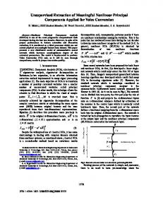
where droop coefficient for ; droop coefficient for ; rated power level of unit . The stability is increased by increased coefficients. The coefficients of the active power can be made very small. This is due to the very strong coupling between the active power and the angular displacement of the two voltages. The coupling between the voltage amplitude and the reactive power is weaker. Therefore, the droop coefficient must be somewhat larger to ensure a proper sharing of reactive power. III. NONLINEAR LOAD A proper sharing of nonlinear load currents is not guaranteed by the approach described above. For a 400-Hz converter, the frequency band between the fundamental and the switching harmonics is low, therefore, a rather significant output impedance is introduced by the output filter in order to damp the switching harmonics. The output impedance can be up to 0.3 pu (400 Hz). When harmonic currents are drawn through this impedance the output voltage becomes very distorted and some kind of compensation or control is required to keep the distortion within the required limits [14]. In a 400-Hz system, the controller bandwidth is usually not sufficient to reduce the harmonic voltage contents caused by harmonic output currents and by the lower inverter-induced harmonics. The fundamental voltage is typically controlled as dc values in a rotating reference frame or by the voltage vector amplitude and the angular speed. In such a system, the harmonic load currents will be divided by the inverters, depending on the component variations of the two systems. If the harmonic voltage content on the output is reduced by integrating a harmonic compensation, the compensation will amplify the component differences of the parallel units. If, the parallel-connected units are exactly alike, the units will share the harmonic load equally. Since, this is never the case, the different units will force the voltage at their respective point of control (behind the small interconnection impedance) to be what each unit believe is zero. With a small interconnection inductance ( 5 H) even small differences will force circulating current to flow between the units. To illustrate this, a simplified simulation of two converters in parallel is carried out with controllers applied on the fifth harmonic. The fifth harmonic controller uses a discrete Fourier transformation to detect the amplitude and phase of the fifth harmonic voltage and uses an integrating controller with rather high gain to speed up the process in order to regulate the fifth harmonic voltage component to zero. The two converters in the simulation and their control are identical except for an offset in the calculation of fifth harmonic voltage of 0.2 V (approximate voltage resolution with 12-bit A/D conversion at 200 V line–line). The load is a current source with 100-A linear load and 25-A fifth harmonic load. Active and reactive linear load is shared in the simulation by having fixed frequency and fundamental voltage amplitude. The response is shown in Fig. 4 when the harmonic controllers are applied.
Fig. 4. Simulated fifth harmonic inverter voltage references and current response with harmonic compensation.
The origin of the two current-vector trajectories is the point where the two units would share the fifth harmonic load current equally. Due to small differences in the two units, the currents are forced in opposite directions by the integrating harmonic controllers of the two units. The units are stabilized after some seconds in a position that equals the differences divided by the interconnecting impedance. In Fig. 4, a large amount of circulating current is present. Converter 2 does not only supply the full fifth harmonic load current, it also supplies current into converter 1. Both converters believe the fifth harmonic voltage is zero, but with only small differences, the result is fatal. In the time domain, the currents of phase a are shown in Fig. 5 for the two converters. After 1 s, converter 1 is supplying all the fifth harmonic current. As was seen in the vector diagram of Fig. 4, the two converters move in opposite directions, and the fifth harmonic current is supplied by one unit solely. Due to the small unbalance in the voltage measuring system, the controllers work in opposite directions and, finally, only one unit compensates for the fifth harmonic load currents. Very little distortion is present in the output voltages. In a case where several converters are connected in parallel, the result will be even worse.
IV. SHARING BY
OF HARMONIC LOAD CURRENTS DROOP COEFFICIENTS
In order to damp this struggle of integrating controllers, droop coefficients can be introduced with the harmonic voltages similar to the ones used to adjust the fundamental voltage amplitude and frequency. Consider a converter connected to a busbar through an inductance as shown in Fig. 6. The voltage drop across the inductance is leading the fifth harmonic current vector by 90 (in the V fifth harmonic frame). In order to damp the struggle, each unit has to allow an amount of harmonic voltage proportional to the amplitude of the harmonic current drawn. The harmonic voltage must have a specific phase relation to the current. Therefore, the harmonic voltage at the converter output has to be controlled to be 90 leading the output current.
1820
IEEE TRANSACTIONS ON INDUSTRY APPLICATIONS, VOL. 37, NO. 6, NOVEMBER/DECEMBER 2001
Fig. 7. Illustration of the fifth harmonic control law.
(a)
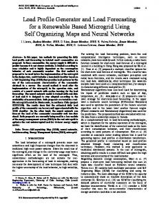
Fig. 8. Simulated fifth harmonic inverter voltage references and current response with the droop coefficients applied.
where (b) Fig. 5. (a) Simulated output currents of the two units, respectively, and total load current. (b) Simulated output voltages and inverter reference of converters 1 and 2, respectively, after stabilizing the integrating controllers (offsets are added to improve illustration).
Fig. 6.
Representation of the fifth harmonic droop coefficient.
harmonic number; reference voltage of the th harmonic; th harmonic output current; droop coefficient for the th harmonic. The reference values have to be calculated for all harmonic, where active harmonic controllers are applied. The harmonic droop coefficient (in V/A) should be chosen small enough to comply with the distortion requirement at the expected harmonic load current. On the other hand, the coefficient should be chosen large enough to overcome errors due to measuring precision and resolution. With converters of different power ratings, the droop coefficient should be adjusted to the rating in the same way as for the fundamental droop coefficient as shown in (5). In the following, the concept will be tested with the fifth harmonic. V. SIMULATION WITH HARMONIC DROOP COEFFICIENTS
In this way, the voltage drop across the interconnection inductance is slightly reduced. A unit with a low amount of fifth harmonic current will not allow as much harmonic voltage as a unit delivering a higher amount of current and the current will be shared without the struggle of the integrating controllers. Divided into real and imaginary components, the control law can be illustrated as in Fig. 7. The control law may be written as
(6)
With the same parameters as in the previous simulation shown in Figs. 4 and 5, new simulations are done and, in this case, a fifth harmonic droop coefficient of 0.1 V/A is applied. the voltage reference and current vector trajectories are shown in Fig. 8. In Fig. 9, the response is shown in the time domain. The differences of the two units are considerably reduced and a stable situation is reached within approximately 0.1 s, much faster than in the previous case (ten times faster). In this case, the load current is divided much more equally between the two converters. The remaining differences are caused by the voltage offset of the harmonic calculators.
BORUP et al.: SHARING OF NONLINEAR LOAD IN PARALLEL-CONNECTED THREE-PHASE CONVERTERS
(a)
Fig. 10.
1821
Load setup for test of fifth harmonic controllers with droop. TABLE I LOAD PARAMETERS
(b) Fig. 9. Simulated (a) currents and (b) voltages and inverter reference after stabilization with the droop controllers.
The fifth harmonic voltage that remains due to the droop coefficients is very small, approximately 1% at this heavily distorted load current. If larger distortion can be accepted, the droop coefficient can be larger, and the sharing will be improved. VI. TEST RESULTS Test results are presented to show the validity of the proposed approach. The concept has been implemented in the control software of two 90-kVA GPUs. The converters are connected to the common point through an inductance of 2 H. The controller samples at 12 kHz. Each fundamental period, the 30 sampled points (12 kHz/400 Hz) are used for the calculation of the fifth harmonic output voltages and currents. The harmonic compensation scheme is updated subsequently. The harmonic droop coefficient is set to 0.2 V/A. Notation refers to Fig. 1. A load, that to a large extent is representative of the mixed loading in the aircraft, is specified in Annex A of the ISO 1540 standard [15]. The load is a combination of 75% linear and 15% rectifier load referring to the converter rating. The amount of nonlinear load on an aircraft has been increasing since the ISO 1540 standard was introduced in 1984. In the following test, a load of two times the expected rectifier 90 kVA GPU system is applied to a common load of a 2 point through a switch. The total load represents 44 kW. The
Fig. 11. Measured currents and voltages at connection of harmonic load with the new concept applied.
load setup is shown in Fig. 10. See [16] for further details about the GPU. For the test, the parameters listed in Table I have been used. In Fig. 11, the rectifier load is switched on. Before the load step small currents are circulating between the two units ( 10 A). At the point of connection, the voltage distortion increases due to the heavy nonsinusoidal current, but the
1822
IEEE TRANSACTIONS ON INDUSTRY APPLICATIONS, VOL. 37, NO. 6, NOVEMBER/DECEMBER 2001
Fig. 14. Measured fifth harmonic voltage amplitude at point of common connection.
Fig. 12. Measured currents and voltages after stabilization of the harmonic controllers. TABLE II MEASURED DISTORTION
currents drawn by the load. The compensation starts to force the voltage vectors to the reference points determined by the currents and the droop coefficients. The harmonic voltages are stabilized 90 leading the harmonic currents. The stationary points of the two units are very close. Finally, Fig. 14 shows how the fifth harmonic voltage amplitude is reduced to a stationary value in approximately 0.5 s. Increasing the gain of the harmonic compensation may speed up the reduction. However, in many cases, there is no need for such high dynamics. VII. CONCLUSION In this paper, a new control concept was proposed that provides sharing of harmonic load currents between parallel-connected converters without mutual communication. In high-power 400-Hz converters, harmonic distortion at nonlinear load can be reduced by harmonic compensation. In a parallel connection, these controllers will fail to ensure a proper sharing and lead to instability. In order to provide harmonic load sharing with the harmonic controllers applied, a new control concept is derived from the well-known concept of sharing linear load by droop coefficients. The concept is simulated and tested on two 90-kVA 400-Hz converters in parallel with heavy nonlinear load, where it has been applied on the fifth harmonic. The concept is proven to share harmonic load without any communication between the power converters. The method can be applied in most solid-state ac power converter topologies supplying nonlinear load. REFERENCES
Fig. 13. The fifth harmonic voltage and current vector trajectories during the transition.
current is shared equally between the two units. In Fig. 12, the harmonic compensation is stabilized and the harmonic distortion of the voltage is reduced dramatically, and still the current is shared equally. In Table II, the distortion factors are shown before and after compensation. In Fig. 13 the fifth harmonic voltage and current vectors are shown. At the time of connection, the voltages rise due to the
[1] J.-F. Chen and C.-L. Chu, “Combination voltage-controlled and currentcontrolled PWM inverters for parallel operation of UPS,” in Proc. IEEE IECON’93, vol. 2, 1993, pp. 1111–1116. [2] S. Tamai and M. Kinoshita, “Parallel operation of digital controlled UPS system,” in Proc. IEEE IECON’91, vol. 1, 1991, pp. 326–331. [3] H. Oshima, Y. Miyazawa, and A. Hirata, “Parallel redundant UPS with instantaneous PWM control,” in Proc. INTELEC’91, 1991, pp. 436–442. [4] A. Ogasawara, H. Satoshi, N. Takagaki, and A. Jin, “A novel control scheme of parallel current-controlled PWM inverter,” IEEE Trans. Ind. Applicat., vol. 28, pp. 1023–1027, Sept./Oct. 1992. [5] J.-F. Chen and C.-L. Chu, “Combination voltage-controlled and current-controlled PWM inverters for UPS parallel operation,” IEEE Trans. Power Electron., vol. 10, pp. 547–558, Sept. 1995.
BORUP et al.: SHARING OF NONLINEAR LOAD IN PARALLEL-CONNECTED THREE-PHASE CONVERTERS
[6] M. C. Chandorkar, D. M. Divan, and B. Banerjee, “Control of distributed UPS systems,” in Proc. IEEE PESC’94, 1994, pp. 197–204. [7] M. C. Chandorkar, D. M. Divan, and R. Adapa, “Control of parallel connected inverters in standalone ac supply systems,” IEEE Trans. Ind. Applicat., vol. 29, pp. 136–143, Jan./Feb. 1993. [8] T. Kawabata, S. Doi, T. Morikawa, and T. Nakamura, “Large capacity parallel redundant transistor UPS,” in Proc. IPEC Int. Power Electronics Conf., vol. 1, 1983, pp. 660–671. [9] A. Tuladhar, H. Jin, T. Unger, and K. Mauch, “Parallel operation of single phase inverter modules with no control interconnections,” in Proc. IEEE APEC’97, vol. 1, 1997, pp. 94–100. , “Control of parallel inverters in distributed AC power systems with [10] consideration of the line impedance effect,” in Proc. IEEE APEC’98, 1998, pp. 321–328. [11] A. von Jouanne, P. N. Enjeti, and D. J. Lucas, “DSP control of highpower UPS systems feeding nonlinear loads,” IEEE Trans. Ind. Electron., vol. 43, pp. 121–125, Feb. 1996. [12] J. Svensson and R. Ottersten, “Shunt active filtering of vector-current controlled VSC at a moderate switching-frequency,” in Conf. Rec. IEEE-IAS Annu. Meeting, 1998, pp. 1462–1468. [13] K. Nakajima and S. Sato, “Harmonic suppression control circuit for a PWM inverter,” U.S. Patent 5 001 619, 1991. [14] Aircraft—Ground Support Electrical Supplies—General Requirements, ISO 6858-1982 (E), Aug. 15, 1982. [15] Aerospace—Characteristics of Aircraft Electrical Systems, ISO 1540-1984 (E), Dec. 1, 1984. [16] U. B. Jensen, F. Blaabjerg, and J. K. Pedersen, “New control method for 400 Hz ground power units for airplanes,” IEEE Trans. Ind. Applicat., vol. 36, pp. 180–187, Jan./Feb. 2000.
Uffe Borup (S’94–M’96) received the Ms.E.E. and Ph.D. degrees in electrical engineering from Aalborg University, Aalborg East, Denmark, in 1996 and 2000, respectively. In 1996, he joined the Institute of Energy Technology, Aalborg University, as a Research Assistant. During this period, he carried out a research project on modeling of power semiconductors in the horizontal deflection circuit on television receivers. The project was supported by the Danish television producer Bang & Olufsen A/S. In August 1997, he joined AXA Power, Odense, Denmark, as an industrial Ph.D. student on the project “Design and Control of a Ground Power Unit.” Since August 2000, he has been an R&D Project Manager with AXA Power. His primary research interests are advance converters for power supplies and drives, including topology, control, harmonics, modeling, characterization of power semiconductor devices, and simulation. He has two patents pending.
1823
Frede Blaabjerg (S’86–M’88–SM’97) was born in Erslev, Denmark, in 1963. He received the Msc.E.E. degree from Aalborg University, Aalborg East, Denmark, and the Ph.D. degree from the Institute of Energy Technology, Aalborg University, in 1987 and 1995, respectively. He was with ABB-Scandia, Randers, Denmark, from 1987 to 1988. He joined Aalborg University in 1992 as an Assistant Professor. In 1996, he became an Associate Professor and, in 1998, he became a Full Professor of power electronics and drives. His research areas are power electronics, static power converters, ac drives, switched reluctance drives, modeling, characterization of power semiconductor devices, and simulation. He is involved in more than 15 research projects with industry. Among them is the Danfoss Professor Programme in Power Electronics and Drives. He has authored more than 200 publications in his research fields. He is an Associate Editor of the Danish journal Elteknik. He serves as a member of the Danish Technical Research Council in Denmark and as a member of the board of the Danish Space Research Institute. Dr. Blaabjerg is a member of the European Power Electronics and Drives Association. He is also a member of the Industrial Drives, Industrial Power Converter, and Power Electronics Devices and Components Committeess of the IEEE Industry Applications Society. He is an Associate Editor of the IEEE TRANSACTIONS ON INDUSTRY APPLICATIONS. He became a member of the Danish Academy of Technical Science in 2001. He received the 1995 Angelos Award for his contribution to modulation technique and control of electric drives, and an Annual Teacher Prize from Aalborg University, also in 1995. In 1998, he received the Outstanding Young Power Electronics Engineer Award from the IEEE Power Electronics Society and an IEEE TRANSACTIONS ON POWER ELECTRONICS Prize Paper Award for the best paper published in 1997. Finally, he received two Prize Paper Awards at the IEEE Industry Applications Society Annual Meeting in 1998.
Prasad N. Enjeti (M’85–SM’88–F’00) received the B.E. degree from Osmania University, Hyderabad, India, the M.Tech. degree from Indian Institute of Technology, Kanpur, India, and the Ph.D. degree from Concordia University, Montreal, QC, Canada, in 1980, 1982, and 1988, respectively, all in electrical engineering. In 1988, he joined Texas A&M University, College Station, as an Assistant Professor in the Department of Electrical Engineering. In 1994, he became an Associate Professor and, in 1998, he became a Full Professor. His primary research interests are advance converters for power supplies and motor drives, power quality issues and active power filter development, utility interface issues, and “clean power” converter designs. He is the holder of four U.S. patents and has licensed two new technologies to industry. He is the Lead Developer of the Power Quality Laboratory at Texas A&M University and is actively involved in many projects with industry while engaged in teaching, research, and consulting in the area of power electronics, motor drives, power quality, and clean power utility interface issues. Prof. Enjeti was the recipient of Second Best Paper Awards in 1993, 1998, and 1999, respectively, and a Third Best Paper Award in 1996 from the IEEE Industry Applications Society (IAS). He received the Second Prize Paper Award from the IEEE TRANSACTIONS ON INDUSTRY APPLICATIONS for papers published from mid-year 1994 to mid-year 1995 and the IEEE Industry Applications Magazine Prize Article Award in 1996. He is a member of the IAS Executive Board and the Chair of the Standing Committee on “Electronic Communications.” He was also the recipient of the select title “Class of 2001 Texas A&M University Faculty Fellow” for demonstrated achievement of excellence in research, scholarship, and leadership in the field. He is a Registered Professional Engineer in the State of Texas.