Peer Review
Shield Placement: Effect on Exposure Melissa P Culp, BS, R.T.(R)(MR) James R Barba, MA, R.T.(R)
Melissa B Jackowski, EdD, R.T.(R)(M)
Purpose In children, red marrow is present in the majority of bones, including the shafts of long bones. Shielding can reduce exposure to radiosensitive tissues adjacent to the collimated field of view. The goal of this study was to determine the shield placement for adjacent bone marrow (bone marrow that is not in the primary beam) that results in the greatest reduction in exposure during knee imaging. Method Radiation exposure was measured with both an ion chamber and a cassette in 2 locations using a knee phantom. Location 1 was directly superior to the collimated field of view facing the primary beam on the anterior surface of the phantom. Location 2 was directly superior to the collimated field of view on the posterior surface of the phantom. Sources of exposure outside collimation include tube leakage, off-focus radiation, scatter radiation, and remnant primary radiation. Results Using an independent 2-tailed t test, it was determined that shielding in the first location resulted in a significant reduction in exposure outside of collimation. Discussion This study reinforced the finding that collimation does not entirely eliminate exposure outside the field of view. Shielding should be used in conjunction with collimation to reduce exposure as much as possible. Shielding on the surface of the patient facing the primary beam results in the greatest reduction in exposure outside of collimation. Conclusion The importance of shielding as much pediatric long bone, and therefore, red marrow, as possible cannot be overstated. Shielding on the surface of the patient facing the primary beam provides the best decrease in exposure outside of collimation.
A
lthough much focus recently has been placed on ionizing radiation dose from computed tomography, conventional radiography remains an essential diagnostic tool in medical imaging. According to the National Council on Radiation Protection and Measurements, plain film radiography represents 74% of all radiographic examinations in the United States.1 In a review of radiation protection in pediatric imaging, Furlow noted that the benefits of knowledge gained from such examinations usually outweigh the radiation risks.2 However, the article emphasizes that children are more radiosensitive than adults. Some children with chronic diseases require long-term care and repeated imaging examinations.3 Undergoing multiple procedures with ionizing radiation will increase the cumulative dose these children receive over time. RADIOLOGIC TECHNOLOGY, March/April 2014, Volume 85, Number 4
Bone marrow dose is significant because marrow is the main organ linked to radiation-induced leukemia.4 Two types of bone marrow exist in the human body. Yellow marrow is primarily fatty tissue, and red marrow is associated with hematopoiesis. In adults, red marrow typically is located primarily in the pelvis, sternum, and other flat bones. However, in children, red marrow is present in the majority of bones, including the shafts of long bones. As pediatric patients mature, the red marrow in their long bone shafts changes into yellow marrow.5 Children born prematurely are especially radiosensitive because of the high mitotic division rate of their cells. When imaging neonates and other young children, the ALARA (as low as reasonably achievable) principle should be followed. Because children have a greater life expectancy than do adults receiving the same examination, they have more time for radiation-induced effects to appear.6 Specifically, 369
Peer Review Shield Placement: Effect on Exposure
an “increased risk of childhood acute lymphocytic leukemia from plain film studies” has been found.7 The current study is significant for radiologic technologists because it reinforces the finding that collimation does not eliminate exposure outside the field of view entirely. Shielding should be used in conjunction with collimation to reduce exposure as much as possible. In addition, this study evaluates 2 shield placement locations to determine which is most effective at exposure reduction. The overall goal is to emphasize the application of the ALARA principle in clinical practice.
Literature Review
The importance of shielding in the reduction of patient dose is well established. Shielding from the primary beam provides the greatest reduction in entrance skin exposure.7,8 In this scenario, pertinent anatomy should not be obstructed by the shield. Many hospitals and health systems are turning from film-screen systems to digital image acquisition systems. With this transition, it has been maintained that “a best practice in digital radiography is the use of lead shielding for anatomic parts that are adjacent to the x-ray field.”8 In addition, the U.S. Food and Drug Administration (FDA) regulations focus on gonadal shielding and reproductive conservation. The FDA recommends that gonads within “close proximity” (5 cm) to the primary beam should be shielded, with at least a 0.25-mm lead-equivalent shield.9 In conventional radiography, technologists are responsible for shield positioning. When shielding tissues adjacent to, but not inside of, the collimated area of interest, one must consider the varying radiosensitivity of tissues.10 According to Furlow, technologists should pay close attention to the protection of the thyroid, eyes, and reproductive organs.2 Because of the relationship between bone marrow dose and possible radiation-induced leukemia, emphasis also should be placed on bone marrow shielding. Aziza and Charkot mention this concern: A conscientious radiographer can do much to protect children from exposure to unnecessary radiation. Bone marrow, active in the formation of blood cells, is distributed through the pediatric skeleton, and tissue damage is associated with ionizing radiation.11 Aziza and Charkot recommend the employment of shielding to protect bone marrow and gonadal tissue in 370
children.11 An important aspect to consider is the proportional length of pediatric long bones. In a smaller child or baby, the entire bone is shorter than in an older child with more mature bones. As a result, it is possible for younger patients to receive exposure to a greater percentage of the shaft (therefore more red marrow) than older patients. The goal of this study was to determine the ideal shield placement for adjacent bone marrow (bone marrow that is not in the primary beam) that results in the greatest reduction in exposure. Traditionally, radiologic technologists have been taught to place the lead shield on the surface of the patient where the central ray enters. When shielding a part inside of the primary beam, this choice is correct because the majority of entrance skin exposure is from the primary beam. The researchers wanted to determine whether this shielding position is optimal for tissue adjacent to the primary beam. The research focus is on the shielding of bone marrow because red marrow is found throughout the pediatric skeleton. An estimate of bone marrow dose is calculated from entrance skin exposure. Two main sources of entrance skin exposure on the surface of the patient facing the primary beam are offfocus radiation and tube leakage. Bushong states: X-ray tubes are designed so that projectile electrons from the cathode interact with the target only at the focal spot and then land on other areas of the target, causing x-rays to be produced from outside of the focal spot….The additional x-ray beam area increases skin dose modestly but unnecessarily…. Finally, off-focus radiation can image patient tissue that was intended to be excluded by the variable aperture collimators.4 The effects of off-focus radiation are minimized by fixed diaphragm tube housing and by the metal enclosure of the tube. Leakage radiation is a result of x-rays escaping the tube housing in all directions and causing an “unnecessary exposure of the patient.”4 If the tube housing is designed correctly, leakage should not exceed 100 mR/hr at a distance of 1 meter. 4 Another consideration for shield placement is positioning between the patient and the image receptor (IR) to reduce entrance skin exposure from scatter and remnant primary beam radiation. When imaging upper limbs on pediatric patients, Aziza and Charkot RADIOLOGIC TECHNOLOGY, March/April 2014, Volume 85, Number 4
Peer Review Culp, Barba, Jackowski
suggest shielding the entire upper body because radiosensitive organs are in close proximity to the “scatter of the primary beam.”11 Johnson specifically mentions the placement of a freestanding or wrap shield between the patient and IR for backscatter protection.12 When discussing pediatric dose reduction, Willis states, “The less anatomy that is exposed to radiation the less effect to the patient, and the less radiation that is scattered…. Less scatter…means less dose to organs in proximity to the radiation field.”13
Methods
During this experiment, measurements of exposure outside of the collimated field of view were obtained. These data allow inference for the best placement of a shield to protect adjacent vulnerable pediatric bone marrow. Exposure was measured in 2 locations using a knee phantom; the knee was in the posterior position for an anteroposterior projection. An Optitop 150/40/80 HC-100 tube (Siemens) was used to create the exposures. (Table 1 contains additional technical information about the equipment.) At the proximal tibia, the phantom measured 10 cm in the midcoronal and midsagittal planes. At the distal femur, the phantom measured 13.5 cm in the midsagittal plane and 12.5 cm in the midcoronal plane. The phantom was placed on the tabletop in a sponge support, and a source-to-image distance of 40 inches (88 cm) was used. The femur end of the phantom was oriented at the cathode end of the tube, and the tibia end of the phantom was oriented at the anode end of the tube. The central ray was centered to the joint space and angled 5° cephalic. For the study, the researchers used the small focal spot and a technique of 60 kVp and 4 mAs. The field of view was collimated to 24 × 15 cm, half the size of a 24 × 30 cm (~10 × 12 in) IR. Location 1 was directly superior to the collimated field of view on the anterior surface of the patient; entrance skin exposure here would be due to tube leakage and off-focus radiation. Location 2 was directly superior to the collimated field of view on the posterior surface of the patient; entrance skin exposure between the patient and IR would be due to scatter and remnant primary beam radiation. The measuring device in location 2 always had a 0.5-mm leadequivalent shield between it and the primary beam; RADIOLOGIC TECHNOLOGY, March/April 2014, Volume 85, Number 4
Table 1 Equipment Technical Information Equipment Type
Technical Information
X-ray tube
Siemens Optitop 150/40/80 HC-100 Model No. 3345209 Serial No. 09646 1.5 mm Al/80 kVp Additional filtration: 1.0 mm Al Focal spot sizes: 0.6 mm/1.0 mm
Computed radiography reader
Fujifilm XG5000 Model No. CR-IR 362 Serial No. 56722192 Manufactured July 2005 Last maintenance was in January 2013
Computed radiography console
Fujifilm Dell manufactured computer Model No. DCNE Serial No. DTK2S81 Manufactured November 2005
Image receptors
Fujifilm 14 × 17 in (35.4 × 43.0 cm) IP cassette type C, ST-6
Ion chamber
MDH Industries Inc Serial No. 1552 Settings: Pulse/fraction threshold: 0.2 Measuring exposure: mR Barometric pressure = 1 atm
Abbreviations: Al, Aluminum; atm, atmosphere; kVp, kilovoltage peak; mR, milliroentgen.
this placement aimed to ensure that the majority of photons measured were from remnant primary and scatter radiation from the phantom. A knee phantom was used because bone marrow exposure in the femoral shaft of pediatric patients is a concern. In addition, the amount of scatter created by an adult-sized pelvis phantom would not be representative of a pediatric patient’s body habitus. The knee phantom is morphologically smaller and is a better reflection of pediatric scatter production. Trial A The null hypothesis for trial A was that there would be no significant difference in exposure at location 1 at 0 inches vs location 2 at 0 inches. In trial A, the 371
Peer Review Shield Placement: Effect on Exposure
study used an ion chamber to measure exposure in locations 1 and 2. An ion chamber provides a measurement in milliroentgen (mR) at a specific location. When measuring location 2, a lead shield was placed between the ion chamber and the primary beam (see Figures 1 and 2). The exposure was measured at an initial distance of 0 inches from the top of the phantom. Next, the ion chamber was moved 2 inches and then 4 inches from the top of the phantom. Exposure was measured at each distance. These data showed the level of exposure as the distance from the body part increased. Each location and the distance intervals were measured 20 times. Trial B The null hypothesis for trial B was that there would be no significant difference in exposure at location 1 vs location 2. The same experiment was conducted again using a cassette to measure exposure rather than an ion chamber. The researchers used a Fujifilm 24 × 30-cm IR. Fujifilm uses an “S” number, or sensitivity number, to provide a numerical indicator of radiation exposure (mR). An S number of 200 is equal to 1 mR of exposure to the cassette.14 The resulting S number is an average of exposure across the entire plate. The size 24 × 30 cm was chosen because it can measure exposure over a large area. An advantage of the IR is that the pattern of scatter can be seen on the resulting image. Because the equipment was readily available, the use of the cassette, Fujifilm reader, and Fujifilm computed radiography console were cost effective and could be replicated easily. To measure exposure at location 1, the cassette was placed facing forward and perpendicular to the central ray superior to the phantom directly outside of the collimated area of interest. The cassette was elevated on a sponge so it was positioned level with the anterior surface of the phantom. To measure exposure at location 2, the measuring cassette was placed backward and perpendicular to the central ray above the knee phantom directly outside the collimated area of interest. The cassette was level with the posterior surface of the phantom. Trial B location 2 was measured using 0.5-mm lead shielding on the back of the IR to minimize photons coming through the back of the cassette. The IR was processed using the auto-process function on a Fujifilm computed radiography console. Each location of the 372
IR was measured 20 times; the same cassette was used for the entire experiment. After each exposure, the cassette was read by the plate processor and erased by an intense white light to ensure that no residual latent image remained. 4 The amount of exposure to the plate was relatively small ( 1 mR), so no additional erasures were warranted (see Figures 3 and 4).
Results
Trial A The data were analyzed with Excel 2010 (Microsoft) using an independent 2-tailed t test. The null hypothesis for trial A was that there would be no significant difference in exposure at location 1 at 0 inches compared with location 2 at 0 inches. Table 2 presents the statistical analysis for trial A. The critical P level (also called the alpha level) was set at .05. There was a significant difference in exposure between location 1 at 0 inches (mean = 0.369, standard deviation = 0.012096) and location 2 at 0 inches (mean = 0.173, standard deviation = 0.011743, t38 = 51.99, P .00001). Based on these results, the null hypothesis was rejected (P .001, 2-tailed). There is a significant difference between the exposure at location 1 at 0 inches compared with location 2 at 0 inches. Trial A was measured moving the ion chamber at 0, 2, and 4 inches. See Table 3 for exposures at locations 1 and 2. Trial B For trial B, S numbers were converted to mR using the following calculation in Excel: 1 mR = an S number of 200 1 mR x(mR) S200 STrials 1 mR(STrials) S200(x(mR)) 1 mR(STrials) x S200 The null hypothesis for trial B was that there would be no significant difference in exposure at location 1 compared with location 2 (see Table 4). The critical P level was set at .05. There was a significant difference in exposure between location 1 (mean = 0.029964329, standard deviation = 0.000738) and location 2 (mean = 0.020900348, standard deviation = 0.000622644), t 38 = 41.98, P .00001. The null hypothesis was RADIOLOGIC TECHNOLOGY, March/April 2014, Volume 85, Number 4
Peer Review Culp, Barba, Jackowski
A
B
Figure 1. A-B. Trial A, location 1 setup. The ion chamber is directly superior to the field of view on the anterior surface of the patient at 0 inches. A
B
Figure 2. A-B. Trial A, location 2 setup. The ion chamber is directly superior to the field of view on the posterior surface of the patient at
0 inches with lead shielding. A
B
Figure 3. A-B. Trial B, location 1 setup. The cassette is directly superior to the field of view facing the primary beam. RADIOLOGIC TECHNOLOGY, March/April 2014, Volume 85, Number 4
373
Peer Review Shield Placement: Effect on Exposure
A
B
Figure 4. Trial B, location 2 setup. A. Shield over the image receptor (IR). B. Placement and direction of the IR before lead shielding was
applied. The cassette is directly superior to the field of view facing the posterior surface of the patient with lead shielding.
Table 2
Statistic
Location 1
Location 2
Mean
0.369
0.173
Variance
0.00015
0.00014
Observations
20
20
Pooled variance
0.00014
Hypothesized mean difference
0
rejected (P .001, 2-tailed). There was a significant difference between the exposure at location 1 compared with location 2. Based on the analysis of the data in trials A and B, the null hypotheses were rejected. A significant difference was shown between the exposure in locations 1 and 2. In both trials, the exposure at location 1 was higher than at location 2 (see Table 5). The exposure measured in the primary beam on the surface of the phantom was 23.5 mR, which was obtained with the ion chamber.
df
38
Discussion
t statistic
51.99373182
P(T t) 2-tailed
.00001
t critical 2-tailed
2.024394164
Trial A Statistical Analysis t Test: 2-Sample Assuming Equal Variances
Table 3 Exposure at Locations 1 and 2 in Trial A
Location
Mean exposure (mR) at 0 in
Mean exposure (mR) at 2 in
Mean exposure (mR) at 4 in
1
0.37
0.15
0.05
2
0.17
0.02
Not measureable by ion chamber
374
The results show that there was a significant difference in exposure between locations 1 and 2 in trials A and B. Location 1 was directly superior to the collimated field of view on the anterior surface of the patient; entrance skin exposure here would be due to tube leakage and off-focus radiation. Location 2 was directly superior to the collimated field of view on the posterior surface of the patient; entrance skin exposure between the patient and IR would be due to scatter and remnant primary beam radiation. Using the ion chamber, exposure was 0.37 mR at location 1 and 0.17 mR at location 2. Using the Fujifilm cassette, the average exposure to the IR was 0.03 mR at location 1 and 0.02 mR at location 2. This study showed that placing the shield in location 1 on RADIOLOGIC TECHNOLOGY, March/April 2014, Volume 85, Number 4
Peer Review Culp, Barba, Jackowski
A
Table 4
B
Trial B Statistical Analysis t Test: 2-Sample Assuming Equal Variances Statistic
Location 1
Location 2
Mean
0.029964329
0.020900348
Variance
0.00000054
0.00000039
Observations
20
20
Pooled variance
0.00000047
Hypothesized mean difference
0
df
38
t statistic
41.97950716
P(T t) 2-tailed
.00001
t critical 2-tailed
2.024394164
Table 5 Exposure at Locations 1 and 2 in Trials A and B Trial
Location 1 (mR)
Location 2 (mR)
A (at 0 in)
0.37
0.17
B
0.03
0.02
the anterior surface of the phantom resulted in the greatest reduction in exposure outside of collimation. Strictly for perspective, the exposure on the surface of the phantom within the primary beam was 23.5 mR. This measurement was obtained using the ionization chamber at the central ray entry point on the phantom. The exposure outside of the collimated area of interest was small compared with that inside the primary beam. However, following the ALARA principle, patients should receive the lowest dose possible in the acquisition of diagnostic images. Exposure outside the collimated area of interest does not contribute usefully to the image; therefore, the patient can be shielded from the extra, although small, amount of radiation. This study shows that collimation does not entirely eliminate exposure outside the field of view. Shielding should be used in conjunction with collimation to reduce exposure as much as possible. This practice is especially important in pediatric patients. Dose to long bones directly outside of collimation also results in dose to red bone marrow. In trial A, location 1, exposure at 0 inches was 0.37 mR, exposure at 2 inches was 0.15 mR, and exposure at 4 inches RADIOLOGIC TECHNOLOGY, March/April 2014, Volume 85, Number 4
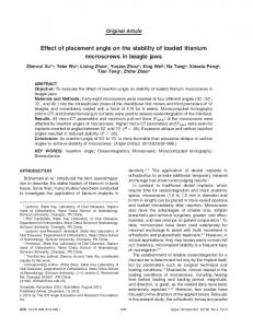
Figure 5. Location 1 (A) features a larger scatter pattern than
location 2 (B).
was 0.05 mR. In trial B, location 1, the scatter pattern showed where exposures fell outside of the collimated area of interest (see Figure 5). Both trials demonstrate that the amount of exposure decreased as the distance from the primary source increased. However, even at a distance of 4 inches, some exposure occurred. It is important to shield a pediatric patient with a high mitotic rate even from this radiation amount. Another consideration is the proportional size of the long bone. The femur of a neonate or infant might be only several inches in its entirety. If the femur of a young patient is left unshielded, proportionally more of the red marrow will be exposed compared with an older child with longer bones. This study measured exposure at 2 possible shielding locations—the surface of the patient facing the primary beam and the surface of the patient facing the image receptor. The dose to the long bone with shielding at the different locations would have given the best answer to the question of optimal shield placement. The research design in this study was limited because the tools used for measuring can only assess exposure. Future studies should investigate the measure of entrance skin exposure using thermoluminescent dosimeters.
Conclusion
This study showed that shielding on the surface of the patient facing the primary beam results in the greatest reduction in exposure outside of collimation. The researchers emphasize the importance of shielding as much pediatric long bone, and therefore, red marrow, as possible. 375
Peer Review Shield Placement: Effect on Exposure
Melissa P Culp, BS, R.T.(R)(MR), is an adjunct assistant professor in the division of radiologic science at the University of North Carolina at Chapel Hill. Her teaching focus is radiographic pathology, positioning, and radiology in global health. In addition, she is the director of radiologic technology programming at RAD-AID International. James R Barba, MA, R.T.(R), is a clinical assistant professor in the division of radiologic science at the University of North Carolina at Chapel Hill. He received his radiography education at the Hudson Area School of Radiologic Technology, completing his studies in 1972. He has a master of arts in educational communication and technology from the Steinhardt School of Culture, Education, and Human Development at New York University in New York, New York. Melissa B Jackowski, EdD, R.T.(R)(M), is a clinical assistant professor in the division of radiologic science at the University of North Carolina at Chapel Hill. Her teaching focus is research and leadership in the radiologic sciences. She is also a member of the Radiologic Technology Editorial Review Board. Reprint requests may be mailed to the American Society of Radiologic Technologists, Communications Department, 15000 Central Ave SE, Albuquerque, NM 87123-3909, or e-mailed to
[email protected]. © 2014 American Society of Radiologic Technologists
computed radiography. Appl Radiat Isot. 2012;71(suppl):5760. doi:10.1016/j.apradiso.2012.04.015. 7. Willis CE, Slavis TL. The ALARA concept in pediatric CR and DR: dose reduction in pediatric radiographic exams— a white paper conference executive summary. AJR Am J Roentgenol. 2005;184(2):373-374. 8. Herrmann TL, Fauber TL, Gill J, et al. Best practices in digital radiography [white paper]. http://www.asrt.org/main/news -research/asrt-white-papers. Accessed December 10, 2013. 9. U.S. Food and Drug Administration. Code of Federal Regulations Title 21. http://www.accessdata.fda.gov/scripts /cdrh/cfdocs/cfcfr/CFRSearch.cfm?fr=1000.50. Revised April 1, 2013. Accessed December 10, 2013. 10. Amis ES Jr, Butler PF, Applegate KE, et al. American College of Radiology white paper on radiation dose in medicine. J Am Coll Radiol. 2007;4(5):272-284. 11. Aziza A. Charkot, E. Pediatric imaging. In: Frank ED, Long BW, Smith BJ, eds. Merrill’s Atlas of Radiographic Positioning and Procedures. 12th ed. St Louis, MO: Elsevier; 2012:101147. 12. Johnson N. Chest. In: Bontrager KL, Lampignano JP, eds. Textbook of Radiographic Positioning and Related Anatomy. 6th ed. St Louis, MO: Elsevier; 2005:75-107. 13. Willis CE. Strategies for dose reduction in ordinary radiographic examinations using CR and DR. Pediatr Radiol. 2004;34(suppl 3):S196-S200. 14. Moore QT, Don S, Goske MJ, et al. Image gently: using exposure indicators to improve pediatric digital radiography. Radiol Technol. 2012;84(1):93-99.
References
1. National Council on Radiation Protection and Measurements. NCRP Report No 160, Ionizing Radiation Exposure of the Population of the United States. Bethesda, MD: NCRP Publications; 2009. 2. Furlow B. Radiation protection in pediatric imaging. Radiol Technol. 2011;82(5):421-439. 3. Stein EG, Haramati LB, Bellin E, et al. Radiation exposure from medical imaging in patients with chronic and recurrent conditions. J Am Coll Radiol. 2010;7(5):351-359. doi:10.1016/j.jacr.2009.12.015. 4. Bushong SC. Radiologic Science for Technologists: Physics, Biology, and Protection. 10th ed. St Louis, MO: Elsevier; 2013:105-122, 548-564. 5. Seeley RR, Stephens TD, Tate P, eds. Anatomy and Physiology. 6th ed. New York, NY: McGraw-Hill; 2003. 6. Frayre AS, Torres P, Gaona E, Rivera T, Franco J, Molina N. Radiation dose reduction in a neonatal intensive care unit in 376
RADIOLOGIC TECHNOLOGY, March/April 2014, Volume 85, Number 4
Copyright of Radiologic Technology is the property of American Society of Radiologic Technologists and its content may not be copied or emailed to multiple sites or posted to a listserv without the copyright holder's express written permission. However, users may print, download, or email articles for individual use.