Short-range DGPS for Mobile Robots with Wireless Ethernet Links Albert0 Valejo
Jorge Lobo
Jorge Dias
Institute of Systems and Robotics Electrical Engineering Department University of Coimbra 3030 Coimbra, Portugal Tel: +35 1-39-796303 Fax: +35 1-39-406672
[email protected]
Institute of Systems and Robotics Electrical Engineering Department University of Coimbra 3030 Coimbra, Portugal Tel: +35 1-39-796303 Fax: +351-39-406672
[email protected]
Institute of Systems and Robotics Electrical Engineering Department University of Coimbra 3030 Coimbra, Portugal Tel: +351-39-796219 Fax: +351-39-406672
[email protected]
will be given. The proposed system will be described and some preliminary conclusions drawn.
Abstract For outdoor mobile robot applications the satellite based GPS system is available for position estimation. Differential GPS can add to the precision but requires a fixed receiver at a know position and some communication link. Typically differential GPS data is sent over dedicated radio links or broadcast. For shortrange applications, were multiple robots move around an outdoors workspace, a wireless ethernet link with multiple access points, and supporting multiple robots, is a good and cost-effective solution. The net can be used, amongst other things, for sending the differential dataji-om a local fwced receiver to the robots. In the article we present a clienthewer model that enables the mobile robot to sign-up with the server and receive the DGPS data over the Internet, allowing the calculation of a more precise position. This provides a simple and flexible method of implementing DGPS corrections. Some field tests are presented that show that this simple approach can provide good results, without being an expensive solution.
1
2
The GPS system was designed for, and is operated by, the U. S. military. Its scope for military missions has been far outgrown with civilian applications, both commercial and scientific. The U. S. Department of Defence funds and controls the system, and civilian users world-wide can use the system free of charge and restrictions. However the accuracy is intentionally degraded for the non-military applications. The satellite-based systems can provide service to an unlimited number of users since the user receivers operate passively (i.e. receive only). The system provides continuous, high accuracy positioning anywhere on the surface of the planet and near space region, 24 hours a day, under all weather conditions. GPS also provides a form of co-ordinated universal time. The users receivers are small and lightweight, making handheld global positioning systems a reality. See Getting [ 11 for a brief history and description of the system or Kaplan [2] for a more detailed description and underlying principles. The GPS system is composed of three segments. The space segment consists of the GPS operational constellation of satellites. The constellation currently consists of 24 earth satellites, including 3 active spares, in 12 hour orbits. They are arranged in six orbital planes, separated by 60" in longitude, and inclined at about 55" to the equatorial plane. The satellites' nearly circular orbit, with an altitude of around 20000 km, is such that they repeat exactly twice per sideral day. This implies that they repeat their ground track 4 minutes later each day. This constellation provides the user with between 5 and 8 satellites visible from any point on earth. GPS operation requires a clear line of sight, and since the signals cannot penetrate water, soil, or walls very well, satellite visibility can be affected by those types of obstacles. The control
Introduction
One of the most relevant external sensors, for outdoor applications, is the Global Positioning System (GPS). In short-range automation applications a precise positioning system is required. GPS alone does not have the required precision. Differential GPS can improve this significantly. The differential corrections have to be sent to the mobile units. The proposed system is intended for multiple robots working outdoors in a short-range workspace. The differential corrections can be sent over a wireless ethernet lmk. This link provides a standard connection for all control and monitoring of the robots, including DGPS
corrections. In the following sections an overview of the GPS system, its errors, and standard DGPS techniques
0-7803-4484-7/98/$10.00 0 1998 IEEE
Overview of the GPS system
334
AMC '98 - COIMBRA
satellite, since the satellite clocks are synchronous [3]. Four satellites will be needed, and the three dimensional position will be given by the simultaneous solution(s) of the four equations. This is done in practice with a standard Newton-Raphson method for solving simultaneous non-linear equations. When more satellites are used, or some prior knowledge is available, a least squares technique is used. When altitude is known, navigation in two dimensions can be done with only three satellites. All satellites broadcast two microwave carrier signals, L1 (1575.42 MHz) and L2 (1227.60 MHz), as well as UHF intra-satellite communications link, and S-band links to ground stations. The dual fiequency approach allows estimation of ionospheric propagation delay at the receiver since the delay is frequency dependent. Satellites use unique Pseudo Random Noise (PRN) codes to modulate the signals, enabling satellite identification at the receiver end. The use of a particular type of PRN codes allows receivers with antenna only a few inches across to extract very low power signals from background noise by correlating them with expectations. The PRN codes of the different satellites are nearly uncorrelated with respect to each other, allowing receivers to "tune in" to different satellites by generating the appropriate PRN code and correlating with the received signal. The receiver computes satellite signal propagation time by shifting the self generated PRN code sequence in time, until the correlation function peaks. The time shift introduced gives the signal propagation time, including clock bias. A precision code (the P-code) is modulated on to both L1 and L2 carriers. The P-code is a very long (seven days) 10 MHz PRN code. This means that acquisition of the P-code signal is slow unless the receiver position and/or time can be accurately initialised. To assist P-code acquisition a coarse acquisition code (the CIA-code) is assigned to each satellite. This 1 MHz PRN code repeats every 1023 bits (one millisecond) and is modulated onto the L1 carrier, in phase quadrature with the P-code signal. The Standard Positioning Service (SPS) available to all users is based on the CIA-code. In the Anti-Spoofing (AS) mode of operation, the Pcode is encrypted into the Y-code. This P(Y)-code requires a classified AS module, available only to authorised users with cryptographic keys, and is the basis for the Precise Positioning Service (PPS). Navigation system data is modulated onto both carriers, using modulo-two addition to the PRN code modulation at a very low data rate [4]. This navigation message is a 50 Hz signal consisting of data bits that describe the GPS satellite orbits, clock corrections, and other system parameters. The satellite's own precise ephemeris data is transmitted as well as less accurate ephemeris data for all satellites, known as the almanac.
segment consists of a world-wide system of tracking stations. A Master Control Station tracks the position of all satellites and maintains the overall system time standard. The other monitor stations measure signals from the satellites, allowing the Master Station to compute the satellites exact orbital parameters (ephemeris) and clock corrections, and upload them to the satellites, at least once a day. The satellite then sends subsets of this information to the user receivers. Satellites have precise atomic clocks, allowing them to maintain synchronous GPS system time. The user segment consists of the GPS receivers. They converl the satellite signals into position, velocity, and time estimates. Position measurement is based on the principle of range triangulation. The receiver needs to know the range to the satellites and the: positions of these satellites. The satellites positions can be determined by the ephemeris data broadcast from each satellite. GPS Satellites
'~, _
.
.
:
'.. ,. , ~.. ; ':; . ,. '. ..,! . . ,_.' ._,
I
_'
~\,
GPS Receiver
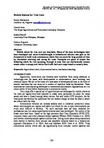
Figure 1: GPS basic idea. The ranges are determined by measuring the signal propagation time from each satellite to the receiver. The receiver needs a local clock synchronised with the GPS system time. The atomic clock used in the satellites are impractical for the user receivers, and cheap crystal oscillators are used instead. These introduce a user clock bias that effectively adds a fourth unknown in the triangulation. The computed range to each satellite will be equally affected by the same clock bias dependent variable. These erronaous ranges are called pseudoranges. To determine position in three dimensions, four equations are needed to determine the four unknowns. For each satellite the folloming equation holds:
where receiver and sa.tellite positions are expressed in Cartesian geocentric co-ordinates, c is a constant, and 2 is the user clock bias, which it the same for every
335
dedicated radio links, or sometimes radio broadcast to multiple user receivers.
The navigation message is updated and repeated every 12.5 minutes.
3
GPS Satellites
GPS errors
,.'
I
. .. .
I
Selective Availability (SA) is a deliberate error introduced to degrade system performance for non-U.S. military and government users. The system clocks and ephemeris data is degraded, adding uncertainty to the pseudo-range estimates. Since the SA bias, specific for each satellite, has low frequency terms in excess of a few hours, averaging pseudo-ranges estimates over short periods of time is not effective [ 5 ] . The potential accuracy of 30 meters for CIA code receivers is reduced to 100 meters. Satellites are subject to deviations from their planned ephemeris, introducing ephemeris errors. The satellite clocks degrade over time, and if the ground control leaves then uncorrected, unwanted clock errors are introduced. The troposphere (sea-level to 50 km) introduces propagation errors that are hard to model, unless local atmospheric data are available. The ionosphere (50 km to 5000 km) also introduces delays, and some compensation can be made with modelling based on almanac data. Dual frequency receivers allow direct estimation of ionospheric propagation delay since the delay is frequency dependent. Shadows and multiple paths can also introduce errors. Shadows reduce the number of visible satellites available for positioning. Multiple path error is caused by reflected signals from surfaces near the receiver and can be difficult to detect and hard to avoid. The reflected signal can either interfere, or be mistaken for, the straight line path signal form the satellite. The geometry of the satellites used for positioning will strongly affect how the pseudo-range error transforms into position error. Poor Geometric Dilution of Precision (GDOP) results when angles from the receiver to the set of used satellites are similar. The overlapping uncertainties of each Satellite form a large volume uncertainty for receiver position. Good GDOP results when the angles are different and the overlapping uncertainty region is smaller.
4
...
,
.. I
.
Mobile
GPS
Receiver
Figure 2: Differential GPS (DGPS). Most of the above mentioned errors are overcome, although some ldce multipath and shadows remain (and to a certain extent tropospheric delays). Most importantly the Selective Availability error is cancelled, allowing typical positioning accuracy of around 100 m to come down to 1-10m. This means that a Standard Positioning Service (SPS) DGPS receiver has higher accuracy than a single Precise Positioning Service (PPS) GPS receiver, however the PPS receiver works standalone, and the SPS DGPS receiver needs a second receiver at a known location to provide differential data. DGPS performance degrades as the distance between the reference and user receiver increases, and is only suitable for distances under 100 km. Another differential technique is the carrier-phase DGPS, also known as interferometric GPS, which bypasses the pseudo-random code and uses the high resolution carriers. The phase shift between signals received at the base and mobile units gives the signal path difference. It is also called code-less DGPS, as opposed to the coded DGPS where the pseudo-random noise code sequence is used to estimate signal path differences for each satellite. This technique is typically used in surveying applications, where accuracy of a few centimetres can be achieved. Besides the high cost, codeless DGPS requires a long set-up time, is subject to cycle slip, and unsuitable for fast moving vehicles. The standard DGPS technique involves sending corrections for each visible satellite signal, meaning that the fixed receiver i s required to track multiple satellites, and also have the raw satellite data available. Such receivers tend to be more expensive. The lower-cost receivers only provide position output. A more simplistic approach to differential GPS is to simply correct the user position with the known position offset of the reference receiver. This can only provide good corrections if both
Differential GPS (DGPS)
The basic idea behind differential positioning is to correct bias errors at the receiver with measured bias errors at a known nearby position. The reference receiver, knowing the satellites' ephemeris and the expected signal propagation delay, can calculate the corrections for the measured transit times. This correction is computed for each visible satellite signal, and sent to the user receiver. These pseudo-range corrections are typically sent over
336
receivers are using tbe same set of satellites. In the following sections such an approach will be presented, intended for short-range applications, such as multiple robots moving around an outdoors workspace.
5
Proposed short-range DGPS "
GPS
Receiver
The basic idea is to implement a low-cost DGPS system over the network, using low-cost GPS receivers. By using the net, a dedicated radio llnk is no longer required. The system ici intended for mobile robots with wireless ethernet links. In short-range applications, were multiple robots are moving around an outdoors workspace, a wireless ethernet link with multiple access points, and supporting multiple robots, is a good and costeffective solution. The net is primarily used for control and monitoring of the robots. It can also be used for sending the differential GPS data from a local fixed receiver to the robots. The GPS receivers used were GARMI"s GPS75 model. This particulm model was chosen for its availability and relatively low-cost at the time of purchase. It can connect to a standard RS232 serial port and gives measurements every two seconds. Cheaper models failed to provide this update rate or suitable outputs to connect to a computer.
Figure 4: mobile GPS and client. The mobile user computer has his own GPS receiver connected to a serial port. He reads in the given GPS positions and applies the corrections given by the server to compute a better estimate of his position. For synchronisation the UTC time is used. Information about the set of satellites used for position calculation on each (server and client) GPS receiver is also sent to the user computer so that the client program can assess if the correction is valid. If the set of satellites is different, a worse quality factor (QF) is given to the correction, and it might not be applied, since it could introduce even worse errors. Figures 5 and 6 show this clientherver implementation.
" UTC i. ALy, ALon&, FixSV,(I-i. 12)
Wireless Link
I
I Differential Data Log file
+ I
1
DGPS Server
Figure 5: Server block diagram. GARMI"s GPS75 model can use three protocols for communication: NMEA 0183, RTCM SC-104 and GARMI". In order to have access to all the required data the ASCII NMEA 0183 protocol was used. This protocol is a standard for naval instrumentationcommunications. It basically specifies the ASCII sentence and delimiter codes for the different data that can be sent, including GPS, engine-room monitoring systems, electronic chart display and information system, heading sensors, velocity sensors, timekeepers and others. Using this protocol, both the server and client program get the geographic position, 1atitudeAongitude of present position, time of position fix and also the information about the identification of the satellites used by their receiver for the solution.
Figure 3: Fixed GPS receiver and server. The proposed system works in a clientherver model. A fixed GPS receiver, lit a known location, is connected to a serial port at the computer running the server program. This program subtracts the known latitude, longitude and altitude position values to the current GPS given position, providing a correcting offset for each coordinate. Several users can then access the DGPS data by sending sign-up requests to the server over the LAN. The server program will then continuously send the differential corrections to the computers that signed-up.
337
,m
:
I
I
I
I
I
I
I
I
LITC i, MobLsl,, MobLong. CMobLat,, CMobLong. QP
+
Mobile Navigation System
Figure 6: Client block diagram. The basic mode is a kind of continuous synchronous mode. An asynchronous mode is also available. In this case the client looks-up data for a specific UTC time and gets the server reply. This way the robot could recover from a broken wireless link, due to some obstacle or interference, and backtrack the path followed by lookingup the passed differential corrections.
6
Figure 8: Mobile unit path around the university campus. indicate the number of common satellites used in the GPS solution, i.e. both by the mobile and f i e d unit. The correction can however become useless when the receivers are not using the same satellites in their solution. For this reason the used satellites' serial numbers are also sent so that the quality of the correction can be assessed. This system is not intended to work stand-alone, but to be fused with other onboard sensors, such as low-cost inertial systems, odometry or others.
Test and validation
150
I
X X
7
-150 X
A simple and flexible DGPS system over a wireless ethemet llnk was presented. The simple approach presented is basically limited by the GPS receiver type used. The same clientherver model over the network can be implemented using DGPS corrections in the pseudorange domain, rather than in position. The price of receivers capable of such implementation is becoming lower. The data to be transmitted would now be larger, but the results should improve significantly, and allow for wider-range applications. In the future we intend to study more deeply the statistic model of the fixed GPS as well as the differential corrections. Prediction mechanisms can then be implemented to overcome possible delays of the communication link between the server and mobile client units.
X
" , I -200
-x)o
.I50
-100
-50
0
M
100
150
Conclusion
200
x(n.ur.)
Figure 7: Fixed GPS receiver measurements. Figure 7 shows a sample of the unfiltered position measurements from a fixed receiver over a two day period. It clearly shows a large positioning error in excess of 100 m. With our proposed system, a mobile robot in the vicinity of the fixed receiver can compensate its position. It accesses, via the network, the server program at the computer to which the fixed receiver is connected. Figure 8 show a preliminary test where the mobile unit was taken along a path in the university campus. It is clear that the correction improvement degrades significantly as the number of common satellites between the server and client decreases. The legend numbers
References [lJ Ivan A. Getting, "The Global Positioning System", IEEE Spectrum, pages 236-247, December 1993.
338
[Z] Elliott D. Kaplan, Understanding GPS: Principles
[4] H. Everett, Sensors for Mobile Robotics, A.K.
and Applications, Artech House, ISBN 0-89006793-7, 1996.
Peters, ISBN 1-56881-048-2, 1995. [5] Peter H. Dana, "Global Positioning System Overview'', Department of Geography, University of Texas at Austin, 1997.
[3] Alonzo Kelly, "Modem Inertial and Satellite Navigation Systerns", Tech. Rep. CMu-RI-TR-9415, Carnegie Mellon University, May 1994.
http://www.utexas.edu/depts/grg/gcraft/notes/~s/~s. html,.
339