late large complex storage networks, with its corresponding underlying ..... to free memory. ... tains server applications, like NFS servers, FTP servers, etc.
SIMCAN: A SIMulator Framework for Computer Architectures and Storage Networks Alberto Núñez, Javier Fernández, Jose D. Garcia, Laura Prada and Jesús Carretero Architecture Group, Computer Science Department Universidad Carlos III de Madrid, Leganés. Spain
{anunez, jfmunoz, jdgarcia, lprada, jcarrete}@inf.uc3m.es ABSTRACT This paper presents an OMNeT-based Framework to simulate large complex storage networks, with its corresponding underlying subsystems (I/O, Networking, etc.). With this Framework, custom environments can be configured and deployed on a flexible and easy way. The most interesting features of this Framework are its flexibility and scalability, so the simulation of distributed storage environments can be performed with the required detail level. Thus, we will able to study the behaviour of complex distributed environments to several purposes, like detecting system bottlenecks, calculating the scalability degree of the system or testing the performance of developed algorithms, without using a real system.
Keywords I/O simulation, distributed systems simulation, network storage simulation
1.
INTRODUCTION
Nowadays, distributed and parallel computing is increasing its role due to the fast evolution on computer networks and communication technologies. The complexity of this systems and the need of storing great amounts of data, suggest that the process of performing studies of real complex distributed environments, will becomes a time-consuming and expensive task. There are two ways to perform studies of complex distributed environments: running tests on a real system or on a simulated environment that represents the real system. The first choice is more complex and expensive; it requires having the real hardware of the system, with their nodes connected with the corresponding network, etc. Meanwhile, performing simulations do not require the real hardware; basically it needs a computer system of any kind to execute the program that simulates the real environment behaviour. Another point to be considered is the speed of the whole testing process. In most cases, developing and performPermission to make digital or hard copies of all or part of this work for personal or classroom use is granted without fee provided that copies are not made or distributed for profit or commercial advantage and that copies bear this notice and the full citation on the first page. To copy otherwise, to republish, to post on servers or to redistribute to lists, requires prior specific permission and/or a fee. OMNeT++ 2008 March 3, 2008, Marseille, France. ACM copyright notice upon transfer of copyright Copyright 2008 ACM 978-963-9799-20-2 ...$5.00.
ing real tests is slower that simulated tests. Moreover, real tests should be performed as they are, while simulated tests can be improved, parallelizing their execution, on a cluster, where the performance can be scaled with the number of nodes involved. The scalability of the tests is another feature to have in mind. Scaling the architecture of the real system is more expensive and time-consuming that performing the same changes in a simulated environment. Generally, simulated environments are parameterized, thus, making a change in the simulated architecture only requires changing some parameters. Another feature that makes simulations a good choice for studying complex distributed environments is when the real system does not exist. Simulation process let us test new architectures before building them. The main problem with the use of simulated tests instead of real tests is the accuracy of the results. The simulations have to obtain results that must be similar enough to those obtained on a real system. Obtaining and assuring this accuracy is the problem that must be solved when designing new simulation environments. Our primary goal is to develop a Framework that let us make simulated storage networks environments with its corresponding underlying subsystems, like the I/O subsystem and networking subsystem. A real storage network contains several components that must been simulated, like Disk Drives, File Systems, Volume Managers, Schedulers, Caches, Communication Networks, etc. Storage subsystem performance is one of the major concerns that arise on this kind of large computing networks. The I/O subsystem is usually a system bottleneck in most of the computing systems. The proposed Framework is being developed using OMNeT++ [1]. OMNeT++ is a discrete event simulation environment that let us develop modules and communicate them. The most important features of the proposed Framework are flexibility and scalability. SIMCAN follows a modular and hierarchical architecture, like OMNeT++. Each module represents a component in the system, that can contain other nested modules, or not. A module that does not contain nested modules represents an independent entity in SIMCAN (for example, a Disk Drive, a File System, etc.). These kinds of modules implement the entity’s behaviour. With our proposed Framework we intend to validate and verify distributed algorithms, locate system bottlenecks and detect poor resources management, with an acceptable accu-
racy degree and performance. To make it possible, a module in SIMCAN can be implemented with a custom detail level, thus we can obtain more accurate results if we implement a module with a high detail level. An example of a high level entity implementation is the emulation of a File System. We can implement a File System algorithm to manage blocks on a module that represents this component. Also, if a module does not require a high detail level, it can be implemented with stochastic models. This last kind of implementation only requires a stochastic model to simulate a component’s behaviour. Mixing these two kinds of implementations, we are able to make custom environments to get the best results and performance. The rest of paper is structured as follows: Section 2 shows some state-of-the-art works. Section 3 presents the architecture of our proposed Framework. Section 4 presents a performance evaluation. Finally, Section 5 presents some conclusions and future work.
2.
STATE OF THE ART
Our work is based on make a Framework that let us simulate storage networks with customized nodes. Each one of those nodes could be a compute node or a storage node, with its corresponding I/O subsystem. At present, there are many kinds of simulation environments, like ONMeT++ [1], Parsec [2] or CSIM [3]. These environments are used to create general purpose simulators and are not oriented to simulate specific systems. OMNeT++ is a component-based, modular and open architecture discrete event simulation environment that provides a component architecture for models. Components (modules) can be parameterized to customize module behaviour. Modules at the lowest level of the module hierarchy encapsulate behaviour and are programmed in C++ using the simulation library. This is a very important feature because we have chosen OMNeT++ to develop the proposed Framework. Currently OMNeT++ is gaining popularity in the scientific community as well as in industrial settings; also simulation models are being published on the Net and can be used freely. PARSEC is a discrete event simulation language. Basically consists on a performed C compiler with the capability to define and create simulation entities and constructors to message communication between entities. Basically PARSEC consists of three primary components: a parallel simulation language called Parsec (parallel simulation environment for complex systems); its GUI, called Pave; and the portable runtime system that implements the simulation algorithms. CSIM is a discrete event simulator for describing parallel processor architectures and software mappings. The CSIM environment consists of a set of tools for describing parallel systems, for running simulations, and for viewing simulation results. The CSIM simulator is the core tool in the tool set. There are several simulation environments to simulate more specific scenarios. For example, network simulators like NS [4] or NetSim [5]. Also, there is a Framework to use with OMNeT++ called INET [6]. NS is a discrete event simulator targeted at networking research. NS provides substantial support for simulation of TCP, routing, and multicast protocols over wired and wireless (local and satellite) networks. NetSim is a even-driven network simulator with X win-
dow support that allow an interactive use. Also, NetSim’s Virtual Packet Technology sets it apart because it actually emulates the functions of a real network - a real network that can be custom-designed. The INET Framework is suited for simulations of wired, wireless and ad-hoc networks. Beyond IP and UDP/TCP there is 802.11, Ethernet, PPP, IPv6, OSPF, RIP, MPLS with LDP and RSVP-TE signalling, and several other protocols. We use INET to establish and perform communication between nodes. INET lacks of high detail level in nodes. Its nodes have applications that make request and serve them, but we need a more specific customizable node with more detail level, especially in I/O subsystem. With those environments we have the network part simulation, but moreover, we need to simulate compute and storage nodes. Also there are several simulation environments to simulate parts of I/O subsystem, like DiskSim [7]. DiskSim is an efficient, accurate, highly-configurable disk system simulator developed at the University of Michigan and enhanced at CMU to support research into various aspects of storage subsystem architecture. It is written in C and requires no special system software (just basic POSIX interfaces). DiskSim includes modules for most secondary storage components of interest, including device drivers, buses, controllers, adapters, and disk drives. In literature we have found few examples of concrete storage networks simulators. Those simulators are focused on specific architectures (SAN, NAS, etc) meanwhile SIMCAN can cover any kind of storage architectures. An example is SIMLAB [8]. SIMLAB is a simulation environment for storage area networks. It is implemented on C++. Currently, the class library of SIMLAB contains models for hard disks, routing nodes and network interfaces. Another work that simulates storage networks is [9]. This work proposes a Storage Area Network (SAN) simulator. This simulator is able to consider both real-world I/O traces and synthetic I/O traffic, message paquetization, faults in links and switches, virtual channels, different routing algorithms, . . . Those works can be an approximation of our aim, but we need a more modular, hierarchical and high detailed model. Also, we intend to make a Framework to build storage networks simulation with a custom detail level, even simulating networking protocols like TCP or UDP and concrete File Systems like Ext2 [10] or reiser File System [11].
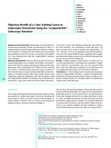
3. ARCHITECTURE The SIMCAN Framework consists of a set of modules. All those modules were developed using OMNeT++. A SIMCAN module (like in OMNeT++) is a building block. The higher level in the SIMCAN architecture consists of nodes, networks and components that communicate them (like routers or switches). A node in SIMCAN can act like a computing node or a storage node. Computing nodes contains applications that performs I/O requests (these kind of nodes can contain, or not, local storage devices). Storage nodes contain a complete I/O storage subsystem, with its corresponding storage devices and the corresponding server application, like a NFS server. An example of SIMCAN architecture is showed in figure 1. In this example several clients (computing nodes) make requests to stored data at storage node (server). In SIMCAN, each module represents a component of a real system; for example: Block Servers, Volume Managers,
Request List
6
Request_2
Request_1
1
Request_3
2
A
B C
Sorted List
5
Z 3
A
Figure 1: SIMCAN architecture
B C
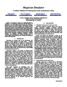
Disk Drives, etc. These modules are nested hierarchically, thus a module can contain zero, one or several modules. A module that does not contain any module is called entity. For example an entity can be a Disk Drive, a File System, a Cache, etc. This kind of modules must implement the entity’s behaviour. Figure 7 shows a Block Server module. This module contains 2 modules (a cache module and a disk module). Each one of these modules (cache and disk) are entities, and contains a corresponding implementation of a cache and disk behaviour, respectively. Modules communicate themselves by message passing. Each module has gates. These gates can be input gates (to receive messages) or output gates (to send messages). Modules are connected with links to pass messages. A link communicates a module output gate with a module input gate. There are situations in which a message has to be split. For example, suppose a node that contains 3 Disks. When a request message arrives to Volume Manager, this module has to make a request to each disk that contains requested blocks. If the request contains blocks that are stored in all disks, at least, Volume Manager will have to make 3 requests, one per disk. To manage this kind of messages, a message library has been developed. This library works as shows figure 2. When a message arrives to a corresponding module, it is stored in a local module list (1). Next, the request message is split (2) on several requests (sub-requests). When all sub-requests had been created, then all of them will be inserted in a sorted list (3). The sort algorithm depends on the class that manages the corresponding module, at present there are several implementations (elevator algorithm, FIFO, etc.). Each one of these sub-requests will be sent to the corresponding module (4) to perform a concrete operation. When these sub-requests arrive to the module that split them, each one will be stored with the original request (5). When all subrequests arrives, then the original request will be sent back as a response message (6) and all sub-requests will be deleted to free memory. If we want to maintain flexibility, we have to develop a message that will be compatible with all modules that composes SIMCAN. In other words, all modules must understand the same message. If we had several message types, we must to develop the same number of modules that understands each one of these messages. Having a standard message, we will not have this problem. The proposed message is a General Purpose Standard Message that is understood by all modules. Basically, this message contains several attributes and a serialized parameter vector. Following parameters are used to: • type: Message type. (For example: Configuration Message, File Request Message, Block Request Mes-
4
Figure 2: Split Message Schema sage, etc.) • isResponse: This field shows if a message is a request message or a response message. • remoteOperation: This field shows if a message contains a remote operation or a local operation. • destination: Destination node (used in remote operations). This field contains the destination node’s hostname. • connectionId: Connection identifier. This field is used to identify a corresponding connection with remote nodes. • trace: Message trace. This trace shows all modules which this message has passed through and the corresponding request number in each of these modules. • nextModuleIndex: Next module index. If a message has to be routed to a module hosted in an array module (for example a File System Array) this field shows the position in this array that contains the corresponding module. • params: Parameter array. The parameter vector is used to send parameters to the corresponding module. Thus we can serialize a message and compute it by the corresponding module. For example, a file request from any application contains 3 parameters: File name, offset and request size. A disk operation will contain 2 parameters; a block list request and an operation type (read or write). All parameters are serialized in the source module and unmarshall in destiny module (like RPCs).
3.1 SIMCAN Hierarchy The major purpose of SIMCAN is to build storage networks. As we said before, the higher hierarchy level in SIMCAN consists by nodes, networks a communication devices (like routers or switches). Basically a storage network consists of several nodes, a network and one or several switches or routers that connect nodes themselves using the communication network. At present there are developed two node types: computing nodes and storage nodes. A computing node (figure 3) contains applications that generate I/O requests. These requests can be local o remote request. A computing node can contain a local I/O subsystem, or not.
to/from Net
to/from Net
NET Modules
NAL
Application NFS Client
Application
Virtual File System
Figure 3: Computing Node Schema Figure 6: Node that uses basic NET simulation The other node type is the storage node. This kind of node must contain an I/O subsystem. Generally, this node serves I/O requests from computing nodes. This node contains server applications, like NFS servers, FTP servers, etc. Figure 4 shows a storage node schema. Networking subsystem consists of all modules related to send messages between nodes and devices (like routers or switches) that perform it. At present in SIMCAN, we can use the INET Framework to simulate real networks like Ethernet, using real protocols, like TCP/IP or UDP (figure 5).
3.1.1 Block Server Basically, a Block Server serves I/O requests. This module contains two entities: a disk Cache and a Disk drive (figure 7). The cache module can be removed, thus a Block Server will act like a disk drive without cache.
Cache
to/from Net
Disk
NET Modules NFS Server FTP Server
Figure 7: Block Server Schema Virtual File System File Systems Volume Manager Block Servers
Figure 4: Storage Node Schema
to/from Net
INET modules
Application
Figure 5: Node that uses INET Framework Another way to simulate a network is using basic features provided of OMNeT++ to simulate networks. This features includes propagation delay, bit error rate that specifies the probability that a bit is incorrectly transmitted and channel bandwidth. Obviously, first option is very much complex and cost-expensive than second, but is very much accurate. With the basic Net no protocol is used (TCP, UPD, etc.). There is no connection established stage, socket connection or anything else. Thus, a new module has been developed to provide this support. This module is called NAL (Net Abstraction Layer). This module acts like a Net Interface, creating connections (like sockets) and managing all connections with corresponding applications (figure 6). The next step on SIMCAN hierarchy is the modules that compose a node. Next, all developed modules in SIMCAN are explained.
This cache contains file blocks. Thus, all requested blocks that are stored in cache, will not been requested to disk. Also this cache is parameterized; we can configure its hit ratio and latency time. A cache memory can be configured establishing several parameters like latency time and hit ratio. At present day, there are implemented several kinds of cache in SIMCAN, like file cache and block cache with several algorithms like LRU (Last Recently Used). Others features implemented in the cache module are the read-ahead functionality (with a customizable window size) and the write-back functionality. The disk drive serves block requests and calculates the service time of a corresponding I/O operation. A message with a block list and an operation type (read or write) arrives to disk. It calculates the service time to perform the requested operation. At present day there are developed several Disk drives in SIMCAN; for example, a Seagate ST3320620AS. Also, DiskSim library have been added to SIMCAN, thus a DiskSim disk can be used like a Disk module in SIMCAN. A pending task is to implement a solid disk, thus a comparison with another strategies with no hardware limitations can be made.
3.1.2 Volume Manager Basically this module manages I/O requests. A Volume Manager is connected to 1..N Block Servers. One of the main tasks of this module is to redirect incoming requests to the corresponding Block Server that contains the requested blocks. This module contains three entities: a Volume Manager, a Cache and a Scheduler. Cache and Scheduler can be removed, this way we can configure a Volume Manager without cache and/or without scheduling policies. It is important to remark the difference between the Volume Manager Module and Volume manager Entity. First
a module in SIMCAN. A File System is a good example to show these two ways. First way is to emulate the File System behaviour. Thus, the corresponding algorithms must been written:
Cache
Scheduler Volume Manager
• Managing the distribution of the file blocks on the disk. Figure 8: Volume Manager Schema one is a module that contains several entities (figure 8). Last one is an entity that contains a Volume Manager logic. With this configurable and customizable Volume Manager Module, we can implement several Disk Systems, like general purpose Disk Drive, RAID 0 (Striping), RAID 1 (Mirroring), RAID 5 (Striping with Parity), RAID 6 (Independent Data Disks with Double Parity) , etc [12]. The Volume Manager entity manages I/O requests, specifically block requests. A Volume manager is associated to one or several Block Servers. The aim of a Volume Manager is to redirect the corresponding block request to the Block Server that contains the requested blocks. Each Volume Manager contains its own scheduling policies, thus, Volume Managers can implement load balancing algorithms to improve the disks accesses performance. A scheduler manages requests using a corresponding scheduling algorithm. Depending on component that uses a scheduler, it will use a corresponding algorithm. For example, a Volume Manager module could use a scheduler with an Elevator Algorithm to improve the disks performance; or a Round-Robin algorithm, or a FIFO algorithm, etc. Schedulers can use libraries to manage split messages. Those libraries had been developed to be used in SIMCAN modules, as we told in section 3.
3.1.3 File System This module simulates a File Systems behaviour. One of the main tasks of a File System is file block managing. It is directly involved in the total service time. At present there are several techniques and algorithms for this purpose. An example is the methodology used in Ext2 File System (bitmaps and i-nodes) or the File Allocation Table (FAT) used in DOS File System. The way that service time is affected by file block managing is due to the movement of the disk heads between two consecutive requests. Thus, the more the file blocks are grouped together, the less distance the disk head has to cover. As a result, a smaller service time will be obtained. Because of this, common file distributions tend to appear as a set of grouped blocks, where those groups are separated along the disk. Figure 9 shows an example of a typical distribution of file blocks.
• Managing free blocks. • Storing and managing file metadata information. • Mapping the requested file blocks into the corresponding disk blocks. The first method is less interesting because it is difficult and complex to implement. It requires storing a great amount of metadata. It should be also remade each time there was a File System change, etc. Another way to implement a File System is making a stochastic model corresponding to the File System behaviour [13]. The factors involved on the allocation distribution for a certain file are quite a few, but there are three of them with capital importance: • Type of File System, because each one has its own strategies to manage free blocks and file distribution. • The amount of free blocks remaining on the disk, because as the number of free blocks increase, the block group sizes increase as well. • The file size, because as the file size increases, the number of block groups increase as well and also their size. The purpose of make a stochastic study is to obtain the file block distribution for a given File System. Usually this is obtained by implementing the File System behaviour. This is a very complex and difficult approach. In contrast, a stochastic model let us obtain a file distribution using statistical methods and distributions. This approach has the following advantages: • It is easier to implement than the File System behaviour. • This method does not require a great amount of stored metadata. • It does not need to be re-implemented for each kind of File System.
File 1
2
3
4
5
6
. . . 15 16 17 18 19 20 21 22 23 24 25 26 27 28 29 30 . . . Block bunch
Disk
Hole
Figure 9: File blocks distribution along the disk surface As we told in section 1, there is two ways to implement
The stochastic model is focused on the way the file blocks are grouped. So file block distribution can be modelled a as a set of block groups (that we call block bunches) separated by a number of blocks that do not correspond to this file (we call this a hole). Therefore, we will have files with only one bunch (we call them contiguous files), and others that are composed by several block bunches separated by a hole (we call them non-contiguous files) as we can see in figure 9. This block distribution model let us estimate the service time by obtaining which are the head movements.
3.1.4 Virtual File System This module simulates a Virtual File System behaviour. Thus, given a corresponding interface, this module redirects I/O requests to the corresponding File System. Also, this Virtual File System is able to manage mounted partitions across the net. So, this module can send remote I/O requests to remote nodes that contain the requested blocks. Figure 10 shows a Virtual File System schema. This module contains two entities: a cache and a Virtual File System that implements the Virtual File System logic. Cache module can be removed, thus all requests will be sent to the corresponding module.
Cache Virtual File System
Figure 10: Virtual File System Schema The Virtual File System entity manages file requests and redirects them to the corresponding File System. This module reads a configuration file that contains information about the interface and corresponding partitions on existing File Systems. Also, a Virtual File System can manage remote File System requests.
3.1.5 Applications In SIMCAN, all entities that represent an application can be divided in two types: client and servers. A client application generates requests and server applications receive requests to process them and sent back a response to the corresponding client application. An example of a client application can be a Trace Player Application. This application read a file that contains a trace with operations and performs them in SIMCAN. Thus, the behaviour of real applications in a real system can be reproduced in SIMCAN. An example of server application can be a NFS Server. One of the major goals of this work is the possibility to reproduce real system behaviours in SIMCAN. To perform it, the behaviour of real applications must be reproduced in a simulated environment. As we told before, Trace Player Application performs this task. Thus, this application can reproduce the execution of several real applications, due to it depends only of its execution trace. This trace is created while a real application is executed in a real system. All performed operations belonging to a corresponding application are handled and written to a file. This file will be the trace that later an application module in SIMCAN will reproduce in a simulated environment.
Once a network topology is defined, all modules that compose that network must be configured. Each module has its own parameters. Those parameters must be specified in the config file. The way to set those parameters follow the syntax parameter = value. When the simulation starts, a set of text files with the simulation results are generated. Each module generates its own results file. Also, a global output file is generated. The generated data in the output files is configurable. The most important data are queues lengths, response times, waiting time, transmission times, bandwidth, etc. Another additional data is the complete message trace, log and debug messages. In a config file we can define the data that will appear in the result files (output files). The generated output is treated later with AWK-scripts to generate graphics. In a near future, a graphical application to show those results and generate graphics automatically will be developed. Thus, any user is able to study a complete message trace to validate the simulation and generate graphics to observe as global network results as local module results.
4. PERFORMANCE EVALUATION In order to check the accuracy of the proposed Framework, a comparative between a real system and a simulated environment (created using SIMCAN) that represents that system has to be performed. First step to perform a comparative, between the real system and simulated system, is running the same benchmarks on both systems. Once all benchmarks have been executed, results obtained in the real system and simulated results must be compared. Thus, we can study some features of the simulated environment behaviour, like accuracy, tendency, etc. Figure 11 shows the schema of the system where the benchmarks will be executed. The same system has been simulated using the SIMCAN Framework. This system is composed by two nodes and a switch that connects them.
Figure 11: Test environment schema. The basic features of each node are: • Intel Pentium 4 CPU 3.20GHz with hyper-threading. • Cache size of 1024 KB
3.2 Environment Configuration
• Extended 2 File System
To define an environment (Network) two files are needed: a file that contains the network topology (called network definition file ’.ned’) and a file that contains the configuration of all modules that composes that network (called config file ’.ini’). First of all, a network topology must be defined as the higher level (in network definition file). Basically it consists of nodes, connection devices (like routers or switches), channels and connections between them.
• Seagate Disk (300 GB) The used network to connect nodes with switch is a Gigabyte network. The performed benchmarks consist on read and write files using the NFS protocol. All benchmarks test will be executed on computing node. Storage node contains the I/O subsystem where the files will be created/read/written. Computing node contains a remote mounted directory (using
NFS) on storage node File System, thus, all I/O operations will be executed on that directory. The list of executed test is listed below: • Sequential read of a file of 64 KB. • Sequential read of a file of 5 MB. • Sequential read of a file of 100 MB. • Sequential write of a file of 64 KB.
that if a request consists of 64 disk blocks, 8 requests will be sent to disk. Branch model makes a request to disk per branch. A branch is a set of contiguous blocks stored on disk. Thus, there is less number of accesses to disk, and latency times are reduced. Testing these two kinds of models, we can check which one is the most accurate. The simulated environment also implements a cache system on the client side that includes a read-ahead policy (using a window size of 32 KB) and a write-back policy.
• Sequential write of a file of 5 MB.
14,0 12,0
• Sequential write of a file of 100 MB. Each test has been executed using several block sizes (2 KB, 4 KB, 8 KB, 16 KB, 32 KB and 64 KB). These block sizes corresponds with the size that the benchmark uses to read data from files and write data to file. To perform all those test we have used the IOR benchmark [14]. In order to obtain reliable test results, each test configuration has been executed 100 times. A configuration test is given by three parameters:
Time (s)
10,0 8,0 6,0 4,0 2,0 0,0 2KB
4KB
8KB
16KB
32KB
64KB
Block Size
Block Model
Branch Model
Real
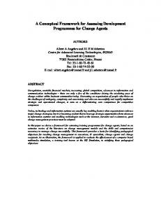
Figure 14: Sequential File Read (100 MB)
• File operation: read or write. • File size: 64 KB, 5 MB or 100 MB
0,035 0,03 0,025
Time (s)
• Block size: 2 KB, 4 KB, 8 KB, 16 KB, 32 KB or 64 KB.
0,02 0,015 0,01
0,035
0,005
0,03
0 2KB
4KB
8KB
Time (s)
0,025
16KB
32KB
64KB
Block Size
0,02
Block Model
Branch Model
Real
0,015 0,01
Figure 15: Sequential File Write (64 KB)
0,005 0 2KB
4KB
8KB
16KB
32KB
64KB
Block Size
Block Model
Branch Model
Real
Figure 12: Sequential File Read (64 KB)
0,7 0,6
Time (s)
0,5 0,4 0,3 0,2 0,1
Figure 12, figure 13 and figure 14 show the results of a sequential read of files of 64 KB, 5 MB and 100 MB respectively. In those charts we can see that simulated results follow the same tendency that the results obtained in the real system. In all cases, simulated test spent more time that the test executed on the real system. With files of 64 KB, the two simulated models are almost equals, but branch model is the most accurate. The rest of the charts show a more noticeable difference between these two models. The cause of this is because with small file sizes, disk accesses are practically the same. When we use greater files, we can observe that branch model optimize disk access, reducing latency and get more close to real results.
0 2KB
4KB
8KB
16KB
32KB
64KB
Block Size
Block Model
Branch Model
0,6
Real
Figure 13: Sequential File Read (5 MB)
Time (s)
0,5 0,4 0,3 0,2
All test launched on the simulated environment has been executed using 2 disk models (block model and branch model). These two models calculate exactly the blocks corresponding to a concrete I/O request, and they are based on the Seagate Disk Drive used in the real system. Block model make requests to disk in groups of a configurable number of disk blocks (set to 8 in those tests). This model makes
0,1 0 2KB
4KB
8KB
16KB
32KB
64KB
Block Size
Block Model
Branch Model
Real
Figure 16: Sequential File Write (5 MB)
Figure 15, figure 16 and figure 17 show the results of a sequential write of files of 64 KB, 5 MB and 100 MB respectively. In these charts we can see that simulated results follow the same tendency that the results obtained in the real system. In all cases, simulated test spent more time that the test running on real system, as occurs with file read tests. In all cases, the two simulated models are very close. This occurs because the write operations have a great bandwidth. In this case, disk cache has an important influence. Due to this bandwidth, write operations have almost the same behaviour. 12 10
Time (s)
8 6 4 2 0 2KB
4KB
8KB
16KB
32KB
64KB
Block Size
Block Model
Branch Model
Real
Figure 17: Sequential File Write (100 MB)
5.
CONCLUSIONS AND FUTURE WORK
In this paper we have presented a Framework to make simulated storage networks environments. A first comparative with a real system have been made, performing a comparative with the obtained results of executing a benchmarks on the real system and the results obtained of executing the same benchmarks on its corresponding simulated environment. The study of the comparative between the two commented systems shows that the simulated environment is accurate. The most important feature is that the obtained results in the simulation environment follow the same tendency that the results obtained in the real system. Changing benchmark parameters, like operation type, file sizes and block sizes, all results follows the same tendency that the real system. Future works will simulate more sophisticated environments, with RAID systems and several computing nodes executing several applications. The final goal is to validate our proposed Framework with real distributed complex systems.
6.
ACKNOWLEDGEMENTS
This work has been supported by the Spanish Ministry of Education and Science under TIN2007-63092 contract.
7.
REFERENCES
[1] Andr´ as Varga. The OMNeT++ Discrete Event Simulation System. In Proceedings of the European Simulation Multiconference (ESM’2001), Prague, Czech Republic, June 2001. [2] Rajive Bagrodia, Richard Meyer, Mineo Takai, Yu an Chen, Xiang Zeng, Jay Martin, and Ha Yoon Song. PARSEC: A Parallel Simulation Environment for Complex Systems. Computer Magazine, 31, Issue 10:77–85, October 1998.
[3] Herb Schwetman. Using CSIM to model complex systems. In Proceedings of the 20th conference on Winter simulation, pages 246–253, San Diego, California, United States, 1988. [4] Sandeep Bajaj, Lee Breslau, Deborah Estrin, Kevin Fall, Sally Floyd, Padma Haldar, Mark Handley, Ahmed Helmy, John Heidemann, Polly Huang, Satish Kumar, Steven McCanne, Reza Rejaie, Puneet Sharma, Kannan Varadhan, Ya Xu, Haobo Yu, and Daniel Zappala. Improving Simulation for Network Research. Technical Report 99-702b, University of Southern California, March 1999. http://www.isi.edu/ johnh/PAPERS/Bajaj99a.html. [5] Vipul Gupta and Eugen Schenfeld. NetSim: A tool for modeling the performance of circuit switched multicomputer networks. In Computer Performance Evaluation Modelling Techniques and Tools, volume 794/1994, pages 180–192, 1994. [6] Andras Varga. INET framework, 2007. http://ctieware.eng.monash.edu.au/twiki/bin/view /Simulation/INETFramework. [7] John S. Bucy, Gregory R. Ganger, and Contributors. The DiskSim simulation environment version 3.0 reference manual. Dept. Electrical and Computer Engineering, Carnegie Mellon University, Pittsburgh, PA 15213, June 2003. [8] P. Berenbrink, A. Brinkmann, and C. Scheideler. SIMLAB: A Simulation Environment for Storage Area Networks. In Proceedings of the 9th Euromicro Workshop on Parallel and Distributed Processing, pages 227–234, Mantova, Italy, February 2001. [9] Xavier Molero, Federico Silla, Vicente Santonja, and Jos´e Duato. Modeling and Simulation of Storage Area Networks. In MASCOTS ’00:Proceedings of the 8th International Symposium on Modeling, Analysis and Simulation of Computer and Telecommunication Systems, pages 307–314, Washington, DC, USA, 2000. [10] R. Card, T. Y. Ts’o, and S. Tweedie. Design and Implementation of the second extended File System. In Proceedings of the 1994 Amsterdam Linux Conference, 1994, Amsterdam. The Netherlands, 1994. [11] Reiser File System Home Page, 2007. http://www.namesys.com. [12] David A. Patterson, Garth Gibson, and Randy H. Katz. A case for redundant arrays of inexpensive disks (RAID). In Proceedings of the 1988 ACM SIGMOD international conference on Management of data, pages 109 – 116, Chicago, Illinois, United States, 1988. [13] Alberto N´ unez, Javier Fern´ andez, Jose D. Garc´ıa, Laura Prada, and Jes´ us Carretero. New Techniques for Modeling File Data Distribution on Storage Nodes. In 41st Annual Simulation Symposium (Accepted), Ottawa, Canada, April 2008. [14] William Loewe, Tyce McLarty, and Christopher Morrone. IOR HPH Benchmark, 2003. http://sourceforge.net/projects/ior-sio/.