SIMPLE METHOD OF DYNAMIC YOUNG’S MODULUS DETERMINATION IN LIME AND CEMENT MORTARS 1
Rosell Amigó, J.R.*; 2Pérez F.; 3 Rodríguez Cantalapiedra, I.
1
Department of Architectural Technology II, School of Building Construction of Barcelona. (EPSEB), Universitat Politècnica de Catalunya, España 2 School of Building Construction of Barcelona (EPSEB), Universitat Politècnica de Catalunya, España 3 Department of Applied Physics, School of Building Construction of Barcelona (EPSEB), Universitat Politècnica de Catalunya, España
[email protected]
ABSTRACT This study demonstrates the feasibility of using a simple method to measure the resonant fundamental frequency for determining the MOE (dynamic Young’s modulus) of lime and cement mortars. The procedure follows the instructions stated in the UNE-EN ISO 12680-1 standard for refractory products although in this study the instructions are applied to standardized RILEM 4x4x16 cm test samples made of lime and cement mortars. The simplicity of the procedure as well as its correlation to other measured variables, suggest that it can be widely applied in studies about the evolution of the physical characteristics in lime mortars, such as mechanical strength, static Young’s modulus, carbonation depth, etc.
1.-Introduction With respect to the mortars used for restoration, it is especially important to know its modulus of elasticity. Usually some of the cement mortars overstiffen the building causing changes in its structural performance. Since those restoration mortars are formulated from air limes (with or without puzzolana) and hydraulic limes, it is interesting to know the procedure of the carbonating process, the mechanical resistance gain, the stiffness, etc. One of the basic parameters in the resistance of the materials and therefore in the area of the buildings materials is the Young’s modulus, which indicates the deformation capability of a given material in its linear elastic span depending on the strain to which is subjected. The common method used in laboratory settings is the static testing by which mechanical properties of mortar lime are determined. Bearing in mind the assumption of homogeneity of the investigated media, elastic properties are characterized by a constant-static modulus that determines the relation between the stress and the strain applied.
Another group of techniques involves the application of non-destructive acoustic waves that have been successfully used in other materials such as wood, natural stones and refractory products. The method enabling the determination of the dynamic modulus is relatively simple, inexpensive and suitable also for field application. This non-destructive testing minimizes the possibility of rupture of the material or test specimens which represents a saving on the one hand and on the other provides new results for testing in the estimation of the material parameters. For some of the specific materials, such as natural stone [1] and refractory products [2], the application of analysis methods of its fundamental natural frequency or resonant frequency in order to determine its MOE (dynamic Young’s modulus) has been standardized although this standardization has not been made in the case of the mortars. 2.-Objective The aim of our work is to obtain some preliminary results for evaluating the possibility of applying the non-destructive test based on the resonant frequency analysis of mortars samples RILEM 4x4x16 made from very simple and economic elements. With the aim to refine the determination of the mortars modulus of elasticity, some standards could be determined by the investigation. Some of the tests we can use to calculate the relative reliability of those standards are: -
-
MOE (dynamic elasticity modulus of elasticity) determination test by impulse excitation of vibration and the subsequent analysis of the resonant basic frequency. MOE determination test from the velocity at which ultrasonic impulses propagates through the sample. Static flexural test to obtain the linear spam of the stretch-deformation graph. Flexural and compressive fracture test.
3.-Mortars to test Since the main objective of this work is to study the validation and reliability of the non-destructive testing methods, the mention of this point will be brief and only to illustrate results more clearly. The natural frequency analysis test will be applied on standard specimens according to RILEM 4x4x16 cm. The mortars are of 8 different types depending on the conglomerates and sand dosage, but the study is centred on two types of conglomerates (hydraulic lime NHL-3,5 and air lime CL-90 and Portland cement CEM I-42,5) and two types of aggregate granulometric curves of calcareous origin (Table 1).
NHL 3,5 NHL 3,5 NHL 3,5 NHL 35 CC CC CC CC
1: 2,7‐600 1: 4‐600 1: 2,7‐3600 1: 4‐3600 1: 2,7‐600 1: 4‐600 1: 2,7‐3600 1: 4‐3600
CEM I‐42,5
NHL‐3,5
Code
CL‐90
Binder
1 1 1 1 0,6 0,6 0,6 0,6
Sand Max. Size
600 μm 3600 μm W/Sol. 2,7 4 2,7 4
0,4 0,4 0,4 0,4
Water
2,7 4 2,7 4
0,19 0,19 0,15 0,14 0,24 0,22 0,2 0,18
Table 1: Nomenclature and dosage The quantity of water for the mixture has been defined by a settlement in a 155±5 mm shaking table according to standard [3] and the curing process has followed this schedule: -
7 days in a saturated environment in a wet chamber (R.H. >95% and 18◦±1). 21 days in laboratory environment (RH 50% ±5 and 20◦C ±2) Drying in a mould dryer at 60◦C until even temperature.
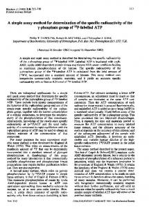
4. Young’s modulus determination In order to find the density of each of the mortar types that constitute the specimens, it is necessary to determine its weight with a precision balance of 0,01 g as well as its length, width and thickness with a gauge (as the slide-gage of 0,01 mm). 4.1. Longitudinal MOE by impact (MOE long) The most important task is to obtain the fundamental mode resonant frequency when the specimen is subjected to an instantaneous pulse (beating) and to register the signal or the frequency spectrum that this beating produces. The analysis of the signal is made by a software obtained in Fakopp [4] and based in the fast Fourier transform (FFT) that directly identifies the value of the higher intensity frequency. A drawing of the equipment is shown in Figure 1. It match the diagram of blocks of the device as shown in [2].
4 1
3
2
Fig. 1. Drawing and picture of the equipment The device is composed of: 1. A plexor with an end made of steel or hardwood; its weight has to be suitable for preventing a physical movement of the specimens when the beating is produced. Appropriate plexor weight has to be a 5% of the specimen weight. The handle of the flexor has to be made of a nonrigid polymer material (methacrylate in this work). 2. Items for supporting the specimens or test samples. The role of the holders in this method is very important since they isolate mortar specimens from external vibrations and their position defines the vibration mode of the samples. flex. Impact
long. impact
0,224∙L
0,224∙L
Fig. 2. Image of the support and impact zones The holders being used are made of triangular prisma-shaped extrusioned polystyrene of 35 kg/m³ density and with sides of 3 cm. The samples are supported by the edges of this prism.
3. Signal register device. Non-contact signal transducers have been used in this study in order to prevent miscalculations caused by the flutters that could be generated by the slightest movement of the samples. Depending on the vibration frequency range of a given material, it will be necessary to choose a transducer able to correctly translate these frequencies. The transducers must be placed in the antinode points fixed in the standard. 4. Signal processing system and analysis software [4]. This is composed of: signal conditioner/amplifier, signal analyzer, display showing the frequency and the analysis of the obtained spectrum. The image of the product we obtain is:
Fig. 3. Screen image reproduction of the software used From the value of the resonant frequency given in Hz, we can obtain the pulse velocity: V = 2Lf V = Velocity L = test sample length (160 mm) f = Resonant frequency
And using the density value, it is possible to calculate the MOE long value: ρ = density
MOE long = ρ v2
The value we use as resonant frequency is the average value of six successive readings obtained with a maximum difference of 1% between them. 4.2. Flexural MOE (MOEflex) by impact Holding the specimens in the corresponding face to the bottom of the mould (face 1), and rotating them 90 degrees and holding in a lateral side of the mould (face 2),
successive readings of the flexural resonant frequencies are made. Specifications described in standard [2] referring to the conditions of the holders, results calculations, etc., have been followed. It is considered a 0, 22 Poisson’s ratio. 4.3. Longitudinal MOE (MOEus) by ultrasound A transmitting and receiving appliance of ultrasound C368 made by Matest, was used for this determination. This appliance has 55 kHz transceiver feelers. It has been measured the required time by the ultrasonic pulse to go through the test sample in longitudinal direction (160 mm) The velocity of the longitudinal propagation of ultrasonic waves through the specimen (V us) has been determined as: V = L/t t = time it takes the ultrasonic waves to go through the sample
Longitudinal MOE by ultrasound has been calculated with the expression: MOElong = ρ v2
4.4. Static MOE by flexotraction The procedure to determine static Young’s modulus has been to manipulate specimens with strain gages and carry out flexural test by means of load increments until the signal stabilization of tensile strength and unital strain (* *). Linear regression in the initial zone of the graph (Figure 5) allows determining the Young’s modulus. With the purpose of facilitating a larger flexural zone, pure and constant, a proof loading system in two points has been used (Figure 4).
40
strain gage
20
40
40
40
20
Fig. 4: Image of the load and supports working points
CC 0.6:0.4:2.7 600 (2)
1,8 1,6 1,4
Traction Stress MPa
1,2 1
y = 8185,x ‐ 0,008 R² = 0,999
0,8 0,6 0,4 0,2 0 0
0,00005
0,0001 0,00015 Strain
0,0002
0,00025
Fig. 5: Strain-traction stress graph in the linear-elastic zone 5. Experimental results and discussion Table 2 represents the results of the non-destructive test for the MOE determination. Absolute errors for the MOE long and MOE flex determination have been omitted since only in one specimen the value exceeded 1%. Values of the coefficients of variation expressed in % (C.V. %) of the results of each mixture, in general lower than 5%, prove the specimens’ homogeneity and the reliability of the measurements.
Test NHL 3,5 1 1: 2,7‐600 2 3 NHL 3,5 1 1: 4‐600 2 3 NHL 3,5 1 1: 2,7‐3600 2 3 NHL 3,5 1 1: 4‐3600 2 3 CC 1 1: 2,7‐600 2 3 CC 1 1: 4‐600 2 3 CC 1 1: 2,7‐3600 2 3 CC 1 1: 4‐3600 2 3
face 1 7656 8346 7752 4450 4612 4584 10392 10279 10934 8423 8741 8316 9791 9781 9255 7771 7510 7657 13511 12987 13303 13630 13493 13038
face 2 7334 8063 7614 4547 4624 4272 9723 10090 10509 8004 8373 7862 9736 9450 9164 7604 7821 7994 12943 13647 12672 13164 13310 12742
MOEflex. (MPa) 7495 8205 7683 4498 4618 4428 10057 10184 10722 8214 8557 8089 9763 9615 9209 7687 7665 7825 13227 13317 12988 13397 13402 12890
C.V. % Media
4,7 7794
C.V. % Media
2,1 4515
C.V. % Media
3,4 10321
C.V. % Media
2,9 8287
C.V. % Media
3,0 9529
C.V. % Media
1,1 7726
C.V. % Media
1,3 13177
C.V. % Media
2,2 13230
MOElong. (MPa) 7024 8521 C.V. % 10,0 7488 Media 7678 3958 4342 C.V. % 4,9 4037 Media 4112 9742 9674 C.V. % 1,8 10010 Media 9809 7876 7928 C.V. % 1,5 7702 Media 7835 9848 9913 C.V. % 0,8 9755 Media 9839 8040 7928 C.V. % 0,9 8064 Media 8011 14225 14212 C.V. % 2,0 13739 Media 14059 13814 13999 C.V. % 3,0 13219 Media 13677
MEAN MOE impact (long. & flex) 7259 8363 C.V. % 7,3 7585 Media 7736 4228 4480 C.V. % 3,3 4233 Media 4314 9900 9929 C.V. % 2,6 10366 Media 10065 8045 8242 C.V. % 2,2 7896 Media 8061 9806 9764 C.V. % 1,8 9482 Media 9684 7864 7796 C.V. % 0,9 7945 Media 7868 13726 13765 C.V. % 1,6 13363 Media 13618 13606 13700 C.V. % 2,6 13055 Media 13453
MOEus (MPa) 8952 10100 8975 5941 5944 5997 12366 13001 12701 10591 10927 10344 12197 11991 11644 10119 10423 10457 16465 16710 15713 19063 18774 17434
C.V. % Media
7,0 9342
C.V. % Media
0,5 5961
C.V. % Media
2,5 12689
C.V. % Media
2,8 10620
C.V. % Media
2,3 11944
C.V. % Media
1,8 10333
C.V. % Media
3,2 16296
C.V. % Media
4,7 18424
Table 2. Results of several MOE The result of the correlation between MOE long and MOE flex is shown in Figure 6, where the accuracy and correlation between both types of determinations are evident.
Correlation between diferents systems to determine MOE
MOElong. vs MOEflex. 16000 20000
y = 0,994x R² = 0,961
y = 1,275x + 14,90 R² = 0,925
8000
16000
12000
4000 MOEflex. face 1
NHL 3,5
8000
MOEflex. face 2
CC
y = 1,167x + 847,1 R² = 0,975
0 8000
12000
16000
4000 4000
MOElong.
12000
4000
8000
0
16000
y = 0,972x R² = 0,973
MOEus
MOEflex.
12000
MEAN MOE impact
Fig. 6. Correlation between MOE long Fig. 7. Correlation between MOE impact and MOEflex. and MOEus. Figure 7 compares the results obtained by impact (average MOE long and MOE flex) with those determined by the velocity at which ultrasonic waves propagate. The correlation is excellent (R²of 0,97 and 0,92) although the values obtained by ultrasound are clearly higher (16 and 27%) than the impact ones. Results corresponding to the determinations of the elasticity modulus by static flexure (E flex) and stress values of the flexotraction and compression tests are shown in table 3. Coefficients of variation values of the results of each mixture are clearly higher than the previous ones. As for the Young modulus, variability fluctuates between 5 and 18%.
Test NHL 3,5 1 1: 2,7‐600 2 3 NHL 3,5 1 1: 4‐600 2 3 NHL 3,5 1 1: 2,7‐3600 2 3 NHL 3,5 1 1: 4‐3600 2 3 CC 1 1: 2,7‐600 2 3 CC 1 1: 4‐600 2 3 CC 1 1: 2,7‐3600 2 3 CC 1 1: 4‐3600 2 3
E bending 7354 10055 8590 4684 4894 5392 10765 9167 10038 8480 7702 8405 10526 8185 8290 8914 10767 9020 12425 13428 15468 12040 11174
C.V. % Media
15,6 8666
C.V. % Media
7,3 4990
C.V. % Media
8,0 9990
C.V. % Media
5,2 8196
C.V. % Media
14,7 9000
C.V. % Media
10,9 9567
C.V. % Media
5,5 12927
C.V. % Media
17,6 12894
Traction stress Mpa 1,34 1,37 C.V. % 1,5 1,33 Media 1,35 0,78 0,83 C.V. % 6,0 0,88 Media 0,83 1,9 1,75 C.V. % 4,4 1,78 Media 1,81 1,09 1,12 C.V. % 5,3 1,01 Media 1,07 2,57 2,13 C.V. % 9,4 2,39 Media 2,36 1,97 2,32 C.V. % 8,2 2,13 Media 2,14 2,10 2,11 C.V. % 5,5 2,31 Media 2,17 2,88 2,51 C.V. % 10,4 2,36 Media 2,58
Compresion Stress MPa 5,4 6,7 C.V. % 15,5 5,1 Media 5,71 2,6 2,8 C.V. % 3,9 2,6 Media 2,64 6,0 6,3 C.V. % 3,4 5,8 Media 6,04 4,6 4,1 C.V. % 6,6 4,2 Media 4,28 10,5 10,5 C.V. % 3,0 10,0 Media 10,33 7,7 8,0 C.V. % 6,2 7,1 Media 7,60 12,0 13,4 C.V. % 7,3 11,6 Media 12,34 12,1 10,9 C.V. % 6,9 10,7 Media 11,24
Table 3. Results of Eflex and flexotraction and compression strength. From the comparative analysis of all the results, we can highlight the high correlation between flexural Young’s modulus and MOE by impact and ultrasound (R²of 0.94 and 0,92) (Figure 8). Linear relations between both methods can be established in the cases we have studied; they follow the expressions: MOE impact = 1,17 · E - 1800 MOE ultrasound= 1,46 · E - 2000 E given in MPa
NHL 3,5 & CC 20000 18000 y = 1,463x ‐ 1996, R² = 0,918 16000
MOE
14000 y = 1,169x ‐ 1796, R² = 0,942
12000 10000 8000 6000
MEAN MOEimpact
4000
MOEus
2000 2000
4000
6000
8000
10000
12000
14000
16000
18000
E flex.
Fig. 8. Relation between MOE and Eflex 6. Conclusions The measurement method of the dynamic Young’s modulus by impulse excitation by vibration is extraordinary simple to use. When applied to mortars, it can be obtained results able to correlate with the other dynamic system studied (MOE by ultrasound) and with the determination of the static Young’s modulus from the flexotraction test. Standardized specimens RI.LEM 4x4x16 used in the ordinary mechanical tests are suitable to measure the dynamic modulus of elasticity. The simplicity of the procedure and the reliability of the measures, as well as the low cost of the equipment (laptop and microphone) suggest that it could have widespread applicability of this procedure as a control tool in mortar factories. In addition, the
method allows classifying mortars with greater simplicity according to their strain capacity and not only to their mechanical resistance. The simplicity of the procedure as well as its correlation to other measured variables, suggest that this can be a methodology widely applied in studies on the evolution of the physical characteristics of lime mortars, such as mechanical strengths, static Young’s modulus, carbonation depth, etc. The aim of this paper is to demonstrate the importance of using non-destructive dynamic tests for solving stability problems of engineering projects. The experimentally obtained Young’s modulus in laboratory indicates than there is a correlation expressed in form of an analytical function that helps to determine the corresponding static modulus. The results have been achieved under simplified assumptions since the relation for Young’s modulus calculation is valid only for homogeneous and isotropic media while lime mortar, in general, does not comply with this condition. Acknowledgments We wish to thank Cal de Pachs, Ciments Molins, Omya Clariana, Alfredo Pérez and Parex Morteros for his collaboration in this study. Also to the Laboratori de Materials of IEPSEB from the UPC.
REFERENCES [4] Fakopp: Acoustic tomography for tree evaluation, www.fakopp.com [1] UNE-EN 14146 Standard: Test method for natural stone. Determination of the dynamic modulus of elasticity (with the measure of the fundamental resonant frequency). December 2004. [2] UNE-EN ISO 12680-1 Standard: Test methods for refractory products. Part 1: Determination of the dynamic Young’s modulus (MOE) by impulse excitation of vibration. September 2007. [3] UNE-EN 1015-3 Standard. Test methods of the mortars for bricklaying. Part 3: Determination of the fresh mortar consistency (shaking table). September 2000.