Kourosh Gharachorloo, Madhu Sharma, Simon Steely, and Stephen Van ... Dan Teodosiu, Joel Baxter, Kinshuk Govil, John Chapin, Mendel Rosenblum, and.
Simple Deadlock-Free Dynamic Network Reconfiguration Olav Lysne1 , Jos´e Miguel Monta˜ nana2 , Timothy Mark Pinkston3 , Jos´e Duato2 , Tor Skeie1 , Jos´e Flich2 1
Simula Research Laboratory Oslo, Norway 3
2
Technical Univ. of Valencia Valencia, Spain
University of Southern California Los Angeles, CA 90089-2562
Abstract. Dynamic reconfiguration of interconnection networks is defined as the process of changing from one routing function to another while the network remains up and running. The main challenge is in avoiding deadlock anomalies while keeping restrictions on packet injection and forwarding minimal. Current approaches fall in one of two categories. Either they require the existence of extra network resources like e.g. virtual channels, or their complexity is so high that their practical applicability is limited. In this paper we describe a simple and powerful method for dynamic networks reconfiguration. It guarantees a fast and deadlock-free transition from the old to the new routing function, it works for any topology and between any pair of old and new routing functions, and it guarantees in-order packet delivery when used between deterministic routing functions.
1
Introduction
System availability and reliability are becoming increasingly important as system size and demand increase. This is especially true for high-end servers (web, database, video-on-demand servers, data centers, etc.), which are currently based on clusters of PCs and/or highly parallel computers. In these systems, the network interconnecting the processing nodes among them and to I/O devices plays a very important role toward achieving high system availability. Since the seminal work of Kermani and Kleinrock on virtual cut-through [17] and later Dally and Seitz on wormhole switching [6, 7], we have seen an ever increasing body of research on these switching techniques. These techniques are in common use today in interprocessor communication (IPC) networks. For a survey of interconnection networks we refer to [11]. In some situations the premises on which the routing algorithm and/or network topology are defined may break, which affects the network’s dependability. This may happen when the topology of the network changes, either involuntarily due to failing/faulty components or voluntarily due to hot removal or addition of components. This normally requires the network routing algorithm (a.k.a., routing function) to be reconfigured in order to (re)establish full network connectivity among the attached nodes. In transitioning between the old
and new routing functions during network reconfiguration, additional dependencies among network resources may be introduced, causing what is referred to as reconfiguration-induced deadlock. Current techniques typically handle this situation through static reconfiguration—meaning that application traffic is stopped and, usually, dropped from the network during the reconfiguration process (see, for example, [24, 26]). While this approach guarantees the prevention of reconfiguration-induced deadlock, it can lead to unacceptable packet latencies and dropping frequencies for many applications, particularly real-time and quality-of-service (QoS) applications [13]. With dynamic reconfiguration, the idea is to allow user traffic to continue uninterruptedly during the time that the network is reconfigured, thus reducing the number of packets that miss their real-time/QoS deadline. Recently, some key efforts have been put toward addressing the issue of deadlock-free dynamic reconfiguration within the context of link-level flow controlled interconnection networks. In [3], a Partial Progressive Reconfiguration (PPR) technique is proposed that allows arbitrary networks to migrate between two instantiations of up*/down* routing. The effect of load and network size on PPR performance is evaluated in [4]. Another approach is the NetRec scheme [22] which requires every switch to maintain information about switches some number of hops away. Yet another approach is the Double Scheme [23], where the idea is to use two required sets of virtual channels in the network which act as two disjoint virtual network layers during reconfiguration. The basic idea is first to drain one virtual network layer and reconfigure it while the other is fully up and running, then to drain and reconfigure the other virtual network layer while the first is up and running, thus allowing “always on” packet delivery during reconfiguration. An orthogonal approach which may be applicable on top of all of the above techniques is described in [18], where it is shown that for up*/down* routing, only parts of the network (i.e., the “skyline”) need to be reconfigured on a network change. In [19] a methodology for developing dynamic network reconfiguration processes between any pair of routing functions is described. All the approaches mentioned above suffer from different shortcomings. PPR [3] will only work between two routing functions that adhere to the up*/down* scheme. NetRec [22] is specially tailored for rerouting messages around a faulty node. It basically provides a protocol for generating a tree that connects all the nodes that are neighbors to a fault, and drops packets to avoid deadlocks in the reconfiguration phase. The Double Scheme is the most flexible of the above, in that it can handle any topology and make a transition between any pair of deadlock free routing functions. On the other hand it requires the presence of two sets of virtual channels. In this paper we present a simple and powerful method for dynamic network reconfiguration. In contrast to the approaches mentioned above, our method is able to handle any topology and any pair of routing functions, regardless of the number of virtual channels available to in the network. It is directly applicable when the new routing function is available, and does not require a new reconfiguration method to be derived before it can be applied. Our technique
guarantees in-order delivery of packets during reconfiguration, and can for that reason off-load much of the fault-handling burden from the higher-level protocols.
2
The Method
We assume familiarity with the standard notation and definitions of cut-through switching and graph theory. In particular we assume that the basic notions of deadlock freedom in general, and channel dependency graphs in particular are known. The readers that are unfamiliar with these notions are referred to [11]. Our focus is on the transition from one routing function to another. We will denote these two routing functions Rold and Rnew respectively, with the subscripts taking the obvious meaning. In what follows we simply assume that each of these are deadlock free and has a cycle free channel dependency graph, unless explicitly stated otherwise. Furthermore we assume that if Rold supplies any faulty channels, the packets destined for these channels are dropped rather than stalled, and that Rnew supplies channels such that the faulty components are circumvented. As we consider transitions from one routing function to another, channel dependency graphs are not a sufficient tool to detect absence from deadlocks. Even if the prevailing routing function at any given time supplies channels in a deadlock free manner during reconfiguration, there may be configurations of packets that are deadlocked. This is because a packet may have made previous routing decisions based on old routing choices that are no longer allowed in the current routing function, and by doing that it has ended up in a situation where it keeps a channel dependency from a previous routing function alive. Such dependencies are called ghost dependencies [19]. We therefore need a notion of deadlocks that encompasses more information than just channel dependencies. We use a simplified form of definition 10 in [27]: Definition 1. A set of packets is deadlocked if every packet in the set must wait for some other packet in the set to proceed before it can proceed itself. We shall use the above definition to show that our reconfiguration method will allow no deadlock to form. In the following we describe the fundamentals of our simple reconfiguration algorithm. In the description we shall for simplicity assume that there will only be one single reconfiguration process active at a time, and that this reconfiguration process will complete before another one is started. Our method is based on two pillars. The first is that we let every packet be routed either solely according to Rold or solely according to Rnew . The packets that we route solely according to Rold will be called old packets, and the packets that are routed solely according to Rnew are called new packets. It is very likely that a channel will be used by both old packets and new packets, so channel dependencies can form from the interaction between old and new packets. The second pillar is the following lemma:
Lemma 1. Assume a transition from Rold to Rnew in which every packet is routed solely according to Rold or solely according to Rnew . Any deadlocked set of packets in such a transition will have to contain old packets waiting behind new packets. Proof. The proof is by contradiction. Assume a deadlocked set of packets in which no old packets wait behind new packets. Case 1: There are no old packets in the set. In that case the set must contain only new packets that should be able to reach their destination using Rnew . This implies that Rnew is not deadlock free, and we have contradiction. Case 2: There are old packets in the set. Since we assume that no old packet wait behind new packets, the old packets must all be waiting behind each other. In that case there must exist a deadlocked set containing only old packets. This implies that Rold is not deadlock free, and we have contradiction. A consequence of the above lemma is that if we make sure that packets routed according to Rold will never have to wait behind packets routed according to Rnew , we will have achieved freedom from deadlock even if Rnew packets wait behind Rold packets. This can be achieved by letting all channels transmit a token that indicates that all packets injected before this token shall be routed according to Rold , and all packets injected after this token shall be routed according to Rnew . We let this token flood the network in the order of the channeldependency graph of Rold , and for each channel it traverses, it means the same thing: all packets transmitted across the channel before this token shall be routed according to Rold , and all packets after this token shall be routed according to Rnew . Every packet routed according to Rnew will simply have to wait for the token to have passed before it enters a channel. That way no packet routed according to Rold will ever have to wait for a packet routed according to Rnew to proceed, thus deadlock cannot form. A more formal description of one version of the process follows: 1. Let each injection link send a token onto all of its channels indicating that no packets that have been routed according to Rold will arrive on this channel. 2. Let each switch do the following: – For each input channel do the following: (a) Continue using Rold until a token has arrived at the head of the queue. (b) When the token has made it to the head of the queue, change into Rnew for this input channel. (c) Thereafter forward packets only to those output channels that have transmitted the token. – For each output channel do the following: (a) Wait until all input channels from which the output channel can expect to receive traffic according to Rold have processed the token. (b) Thereafter transmit a token on the output channel. The following results can now be derived for this process:
Observation 1 All input channels on all switches use Rold until they process the token and thereafter, use Rnew . Lemma 2. This process ensures that all packets are routed either solely according to Rold or solely according to Rnew . Proof. Consider a packet that experiences routing according to both routing functions. On its path from source to destination there will be two consecutive switches, S1 and S2 , where this packet is routed according to different routing functions. There are two cases. Case1: The packet was first routed according to Rold in S1 and then routed according to Rnew in S2 . According to observation 1 this packet must have arrived the switch S2 on an input channel that had already processed the token. Furthermore in S1 it was routed according to Rold , so there it arrived on an input channel before the token was processed on that input channel. Therefore if S2 received the token before the packet, S1 must have sent the token out on the output channel going to S2 before S1 had processed the token on one input channel from which this output channel could expect to receive traffic according to Rold . According to bullet points 2a and 2b for output channels in the process description, this cannot happen. Case2: The packet was first routed according to Rnew in S1 and then routed according to Rold in S2 . According to observation 1 this packet must have arrived S2 on an input link that had not yet processed the token. Furthermore, in S1 it was routed according to Rnew , so there it arrived after the token was processed. Therefore S1 must have forwarded packets from an input link that had processed the token onto an output link where the token has not yet been transmitted. According to the procedure for input channels in the process description, this cannot happen. Corollary 1. Each channel will first transmit only old packets, then the token and then only new packets. Proof. Assume a channel for which the corollary does not hold. Since the method does not discriminate between channels that terminate in switches and channels that terminate in compute nodes, we may without loss of generality assume that this channel terminates in a switch1 . This would either require a new packet to traverse the channel before the token, or an old packet to traverse the channel after the token. In this case the new packet would be routed according to Rold or the old packet would be routed according to Rnew in the next switch. This contradicts Lemma 2. Now we prove that the reconfiguration terminates. Termination requires that all channels will eventually have transmitted the token, thus all input channels in all switches will be using Rnew . 1
This means that if the corollary was not valid for a channel that terminates in a compute node, one could easily generate a topology where the same channel terminated in a switch instead.
Lemma 3. The process terminates with all channels having transmitted the token if Rold has a cycle free dependency graph. Proof. We first prove the lemma for the case where there are no data-packets in the network. Observe that the tokens propagate through the network following the channel dependency graph of Rold . Let o be an arbitrary output channel attached to a switch. Whenever all input channels that have a dependency to o according to Rold have the token at their queue head, the token is transmitted on o. Since the dependency graph of Rold is acyclic, and there are no packets occupying queue space, the lemma follows. The only case we need to worry about is when the propagation of the tokens are hindered by data packets. According to Corollary 1 the tokens can only be waiting behind old packets, and new packets can only wait behind tokens or other new packets. Since Rold is deadlock-free, all old packets will eventually reach their destination or be dropped due to component failure. Therefore no token can be indefinitely blocked, thus the lemma follows. Lemma 4. If both Rold and Rnew are deterministic, in-order packet delivery is maintained during the reconfiguration process. Proof. This is a consequence of Corollary 1. Every channel entering a compute node will first transmit old packets that clearly arrive in order, followed by the token, and finally new packets, that will also arrive in order.
3
Simulation Experiments
In this section we will evaluate the proposed reconfiguration mechanism. First, we will present the evaluation model, describing all the simulation parameters and the networks we have used. Then, we will present the reconfiguration scenarios we have used to evaluate the basic performance of the mechanism. Finally, we will present the evaluation results. 3.1
Evaluation Model
In order to evaluate the mechanism, we have developed a detailed simulator that allows us to model the network at the register transfer level. The simulator models an IBA network, following the IBA specifications [1]. Packets are routed at each switch by accessing the forwarding table. This table contains the output port to be used at the switch for each possible destination. The routing time at each switch will be set to 100 ns. This time includes the time to access the forwarding tables, the crossbar arbiter time, and the time to set up the crossbar connections. Switches can support up to 16 virtual lanes (VLs). VLs can be used to form separate virtual networks. We will use a non-multiplexed crossbar on each switch. This crossbar supplies separate ports for each VL. Buffers will be used both at
the input and the output side of the crossbar. Buffer size will be fixed in both cases to 1 KB. Links in InfiniBand are serial. In the simulator, the link injection rate will be fixed to the 1X configuration [1]. 1X cables have a link speed of 2.5 Gbps. Therefore, a bit can be injected every 0.4 ns. With 8/10 coding [1] a new byte can be injected into the link every 4 ns. We also model the fly time (time required by a bit to reach the opposite link side). We will model 20 m copper cables with a propagation delay of 5 ns/m. Therefore, the fly time will be set to 100 ns. The IBA specification defines a credit-based flow control scheme for each virtual lane with independent buffer resources. A packet will be transmitted over the link if there is enough buffer space (credits of 64 bytes) to store the entire packet. IBA allows the definition of different MTU (Maximum Transfer Unit) values for packets ranging from 256 to 4096 bytes. Additionally, the virtual cut-through switching technique is used. For each simulation run, we assume that the packet generation rate is constant and the same for all the end-nodes. Except when specified, the number of simulated packets is 160,000 and results will be collected from the last 80,000 packets (that is, a transient state of 80,000 packets and a permanent state of 80,000 packets). The uniform traffic pattern will be used. With this pattern, each source sends packets to all the destination with the same probability. Packet size will be fixed to 58 bytes. This includes the IBA packet header (20 bytes), the packet payload (32 bytes) and the IBA packet tail (6 bytes). When using reconfiguration, two packet tokens will be used. The first token will be the start-token and will transmitted from a random switch. This token will be sized in 1 byte and will be broadcasted to all the switches. The second token will be the reconfiguration-token and will be sized in 8 bytes. In all the cases, reconfiguration will be started in the middle of collecting results (in the middle of the permanent state). In all the presented results, we will plot the average network latency2 measured in nanoseconds versus the average accepted traffic3 measured in bytes/ns/switch. Also, the evolution in time of the average packet latency and the average latency from generation time 4 will be plotted. 3.2
Evaluation Results
Different topologies and different combinations of routing algorithms (Rold and Rnew ) has been evaluated. Table 1 shows all the combinations we have analyzed. Due to space limitations we will only display results for case 1 (4 × 4 Torus). The results for all other cases were very similar. 2
3 4
Latency is the elapsed time between the injection of a packet until it is delivered at the destination end-node. Accepted traffic is the amount of information delivered by the network per time unit. Latency from generation time is the elapsed time between the generation of a packet at the source host until it is delivered at the destination end-node.
Case 1 2 3 4 5
Rold Rnew Topology Routing Root Routing Root 4 × 4 Torus UD upper left UD center 4 × 4 Mesh UD upper left UD bottom right 8 × 8 Mesh UD upper left UD bottom right 4 × 4 Mesh XY UD upper left 4 × 4 Mesh XY YX Table 1. Reconfiguration scenarios.
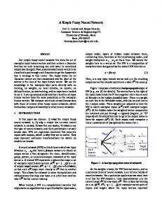
When using the up*/down* routing, the root switch must be selected. In the case of the torus network, the root switch was the upper left switch of the network for the Rold routing, and the center switch of the network for the Rnew . Figure 1 shows the performance evaluation obtained in a 4 × 4 torus network when the reconfiguration is applied. Rnew and Rold use up*/down* (with different root switches). For every simulated point, the reconfiguration mechanism is triggered and the average latency of packets is measured. The Figure also shows the performance when the reconfiguration is not triggered (Rnew is used all the time). As can be noticed, the reconfiguration process slightly affects the performance of the network, and this is visible only at the saturation point. However, these results should be put in context. Since the average latency of packets is measured from the latency of each simulated packet, as the number of simulated packets grows, the percentage of affected packets by reconfiguration will decrease, and therefore, low differences in terms of average latency will appear. The results shown in Figure 1 are taken from simulating 20,000 useful packets (20,000 packets were previously injected before collecting results). The reconfiguration process was launched when 1,000 useful packets were received. In order to better view the impact of the reconfiguration, Figure 1.b shows the reconfiguration latency. That is, the time required by the mechanism to reconfigure the entire network (from the sending of the first start-token up to receiving the last reconfiguration-token). As can be noticed, the reconfiguration latency keeps low and constant for most of the traffic injection rates. For most of the traffic points, the reconfiguration latency is around 1,6 microseconds. The network in the simulations usually gets 666 microseconds to deliver the 20,000 useful packets (with traffic injection near the saturation knee). Therefore, the reconfiguration latency only affects to 0.25% of the simulated time. However, near the saturation knee, the reconfiguration latency increases. At saturation knee, the reconfiguration latency is 49 microseconds, representing 7% of the total simulated time. The reason for this is that only when the network is partly congested, the delivery of reconfiguration tokens will suffer as some old packets will be waiting at some queues during a large amount of time due to congestion. In the normal situation, the queues will not be full, and therefore, the old packets will advance with no delay, so the reconfiguration packets will also quickly advance and propagate. Beyond saturation knee, the reconfiguration tokens also get congested and therefore the reconfiguration latency is excessive.
60000
3000 2500
Reconfiguration latency (ns)
Average Message Latency (ns)
Figure 1.c shows the maximum packet latency for every simulated point. As we can observe, the mechanism practically does not introduce any penalty to packets as the latency for the packet with the maximum latency is practically the same. Indeed, only slight differences appear near the congested knee, where the maximum latency is slightly increased. This is mainly due to the congestion encountered by reconfiguration tokens. Notice that if the network is congested, the old packets will suffer long latencies regardless of the presence of new packets in the network.
’Rold’ ’Rold->Rnew’
2000 1500 1000 500 0
0.01
0.02 0.03 0.04 0.05 Traffic (flits/ns/switch)
(a)
0.06
’Rold->Rnew’
50000 40000 30000 20000 10000 0
0
0.01
0.02 0.03 0.04 0.05 Traffic (flits/ns/switch)
(b)
0.06
(c)
Fig. 1. Impact of the reconfiguration method in a 4 × 4 torus network. Rold is up*/down* (root switch is upper left switch) and Rnew is up*/down* (root switch is bottom right switch). (a) Network latency vs injected traffic, (b) reconfiguration latency, and (c) maximum packet latency.
In order to obtain a closer view to the impact of the reconfiguration method on network performance, Figure 2 shows the evolution of packet latency at different traffic injection rates when the reconfiguration is triggered. The simulated network is a 4 × 4 torus network, Rold and Rnew use up*/down* (with different root switches). In particular, the Figure shows the latency evolution in different traffic loads: low load, medium load and close to saturation (the previous point to saturation). The figure shows results for the average network latency and for the average packet latency from generation time. With vertical lines, the start and the finish of the reconfiguration process is shown. As can be noticed, for low load (Figures 2.a and 2.d), the impact on network latency and packet latency from generation time is not significant. There is no variation in latency in the reconfiguration process. Even more, for medium traffic loads (Figures 2.b and 2.e) the impact on network latency and packet latency from generation time is also negligible. The reason for this is that there are few packets in the network, and therefore, the queues occupancy is also low, so, the reconfiguration tokens can advance quickly throughout the network and switches rapidly change from Rold to Rnew . Indeed, the Figures show average results for every 100 packets delivered. In both cases, the reconfiguration process lasted 1.5 microseconds and 1.9 microseconds, respectively. In that time, less than 100 packets are delivered. Therefore, the impact is minimum for the traffic load.
1000 800 600 400 200 0
3.2e+07
3.3e+07 Time (ns)
1400 1200 1000 800 600 400 200 0
3.4e+07
7000 Start Finish Latency
6.8e+06
Start Finish Latency
1400 1200 1000 800 600 400 200 0
3.2e+07
3.3e+07 Time (ns)
(d)
7.2e+06 Time (ns)
6000
4000 3000 2000 1000 0
7.6e+06
Start Finish Latency
5000
3.8e+06
(b)
3.4e+07
Average Message Latency from Generation Time (ns)
Average Message Latency from Generation Time (ns)
(a)
1600
Average Message Latency (ns)
1200
1600
1600 1400 1200
Start Finish Latency
1000 800 600 400 200 0
6.8e+06
7.2e+06 Time (ns)
(e)
4e+06 Time (ns)
4.2e+06
(c)
7.6e+06
Average Message Latency from Generation Time (ns)
Average Message Latency (ns)
1400
Average Message Latency (ns)
Start Finish Latency
1600
7000 6000
Start Finish Latency
5000 4000 3000 2000 1000 0
3.8e+06
4e+06 Time (ns)
4.2e+06
(f)
Fig. 2. Latency performance during simulation time for (a,d) low load, (b,e) medium load, and (c,f) near saturation. (a, b, c) Average network latency. (d, e, f) Average latency from generation time. 4 × 4 torus network. Rold is UD and Rnew is UD.
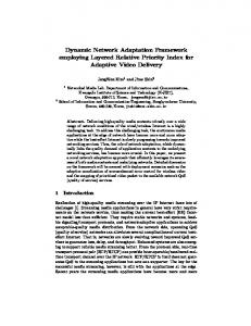
However, for traffic near saturation of Rold (Figures 2.c and 2.f) a much clearer impact on latency is observed. In this case, the reconfiguration process lasted 5.5 microseconds. After the reconfiguration process, we can notice that average network latency sharply increases from 1.5 microseconds to 5 microseconds. Later, the average latency goes back and normalizes to 1.5 microseconds. This temporal increase in latency is due to some introduced blocking of new packets that must wait for reconfiguration-tokens. As the network is close to saturation, queues start to fill and therefore, reconfiguration-tokens start to encounter some degree of blocking. Anyway, this simulated point is very close to congestion, and the negative effect of reconfiguration is low as the reconfiguration process is still fast. Figure 3 shows the behavior in a congested scenario (beyond saturation) of Rold . In this situation, the reconfiguration latency has been increased to 929 microseconds. As can be observed, for the average network latency (Figure 3.a) there is a slight increase on latency in the start of the reconfiguration. However, by the end of the reconfiguration, there is an extremely sharp increase of the latency (from 5 microseconds up to 700 microseconds). The reconfiguration process finishes when the last reconfiguration-token arrives to the last switch. In this switch, there will be new packets blocked since the start of the reconfiguration (as all the switches have compute nodes attached to them and all send packets all the times). Therefore, once reconfiguration is finished, the most delayed new packets will be unblocked and therefore they will reach their destinations, thus
Start Finish Latency
700000
Average Message Latency (ns)
600000
500000
400000
300000
200000
100000
0 4e+06
4.2e+06
4.4e+06
4.6e+06 Time (ns)
(a)
4.8e+06
5e+06
5.2e+06
Average Message Latency from Generation Time (ns)
extremely increasing latency. However, notice that this situation normalizes very fast, as the number of theses packets is quite low.
1e+06 800000 600000 400000 200000 0
Start Finish Latency 4.2e+06
4.5e+06 4.8e+06 Time (ns)
5.1e+06
(b)
Fig. 3. Latency performance during simulation time for saturation. (a) Average network latency. (b) Average latency from generation time. 4 × 4 torus network. Rold is UD and Rnew is UD.
4
Conclusion
In this paper we have described a simple procedure for dynamic and deadlock free reconfiguration between two routing functions. Our method works for any topology and between any pair of routing functions. It guarantees in-order delivery of packets during reconfiguration, as long as the old and the new routing functions are deterministic. And it requires no additional virtual channels. Preliminary evaluation results have shown that the mechanism works efficiently in different topologies and when using different routing algorithms (old and new). The reconfiguration latency is roughly constant for low and medium traffic loads and increases slightly for traffic loads near saturation. The peak latency experienced by packets when reconfiguring is only noticeable for traffic loads beyond saturation. There are several interesting paths for further research that we intend to address in further work. One is the development of simulation results for fault tolerance. Another is connected to the fact that this method is based on routing tables being present in the switches. This means that adjustments need to be made before the method can be applied to source routing. What adjustments should be made, and the effect of such adjustments needs to be studied more closely.
References 1. InfiniBand Trade Association. InfiniBand Architecture. Specification Volume 1. Release 1.0a. Available at http://www.infinibandta.com, 2001. 2. N. J. Boden, D. Cohen, R. E. Felderman, A. E. Kulawik, C. L. Seitz, J. N. Seizovic, and Wen-King Su. Myrinet – a gigabit-per-second local-area network. IEEE MICRO, 1995. 3. R. Casado, A. Berm´ udez, J. Duato, F. J. Quiles, and J. L. S´ anchez. A protocol for deadlock-free dynamic reconfiguration in high-speed local area networks. IEEE Transactions on Parallel and Distributed Systems, 12(2):115–132, February 2001. 4. R. Casado, A. Berm´ udez, F. J. Quiles, J. L. S´ anchez, and J. Duato. Performance evaluation of dynamic reconfiguration in high-speed local area networks. In Proceedings of the Sixth International Symposium on High-Performance Computer Architecture, 2000. 5. W. J. Dally. Virtual-channel flow control. IEEE Transactions on Parallel and Distributed Systems, 3(2):194–205, March 1992. 6. W. J. Dally and C. L. Seitz. The torus routing chip. Distributed Computing, 1:187–196, 1986. 7. W. J. Dally and C. L. Seitz. Deadlock-free message routing in multiprocessor interconnection networks. IEEE Transactions on Computers, C-36(5):547–553, 1987. 8. J. Duato. A necessary and sufficient condition for deadlock-free adaptive routing in wormhole networks. IEEE Transactions on Parallel and Distributed Systems, 6(10):1055–1067, 1995. 9. J. Duato. A necessary and sufficient condition for deadlock-free routing in cutthrough and store-and-forward networks. IEEE Transactions on Parallel and Distributed Systems, 7(8):841–854, 1996. 10. J. Duato, S. Yalamanchili, and L. Ni. Interconnection Networks an engineering approach. IEEE Computer Society, 1997. 11. Jos´e Duato, Sudhakar Yalamanchili, and Lionel Ni. Interconnection Networks: An Engineering Approach. Morgan Kaufmann Publishers, 2003. 12. W. Barrett et al. An overview of the BlueGene/L supercomputer. In Proceedings of the 2002 ACM/IEEE Conference on Supercomputing, CD ROM, November 2002. 13. J. Fern´ andez, J. Garc´ıa, and J. Duato. A new approach to provide real-time services on high-speed local area networks. In Proceedings of the 15th International Parallel and Distributed Processing Symposium (IPDPS-01), pages 124–124, Los Alamitos, CA, April 23–27 2001. IEEE Computer Society. 14. O. Feuser and A. Wenzel. On the effects of the IEEE 802.3x flow control in fullduplex Ethernet LANs. In IEEE, editor, LCN’99: proceedings: 24th Conference on Local Computer Networks: October 18–20, 1999, Lowell, Massachusetts, USA, pages 160–161. IEEE Computer Society Press, 1999. 15. David Garcia and William Watson. ServerNetTM II. Lecture Notes in Computer Science, 1417:119–135, 1998. 16. Kourosh Gharachorloo, Madhu Sharma, Simon Steely, and Stephen Van Doren. Architecture and design of AlphaServer GS320. ACM SIGPLAN Notices, 35(11):13– 24, November 2000. 17. P. Kermani and L. Kleinrock. Virtual cut-through: A new computer communication switching technique. Computer Networks, 3:267–286, 1979. 18. O. Lysne and J. Duato. Fast dynamic reconfiguration in irregular networks. In Proceedings of the 2000’ International Conference of Parallel Processing, Toronto (Canada), pages 449–458. IEEE Computer Society, 2000.
19. O. Lysne, T. M. Pinkston, and J. Duato. A methodology for developing dynamic network reconfiguration processes. In 2003 International Conference on Parallel Processing (ICPP’03), pages 77–86. IEEE, 2003. 20. M. D. Schroeder et al. Autonet: a high-speed, self-configuring local area network using point-to-point links. SRC Research Report 59, Digital Equipment Corporation, 1990. 21. Inc. Myrinet. Guide to Myrinet-2000 Switches and Switch Networks. www.myri.com, August 2001. 22. N. Natchev, D. Avresky, and V. Shurbanov. Dynamic reconfiguration in highspeed computer clusters. In Proceedings of the International Conference on Cluster Computing, pages 380–387, Los Alamitos, 2001. IEEE Computer Society. 23. T. Pinkston, R. Pang, and J. Duato. Deadlock-free dynamic reconfiguration schemes for increased network dependeability. IEEE Transactions on Parallel and Distributed Systems, 14(8):780–794, August 2003. 24. Thomas L. Rodeheffer and Michael D. Schroeder. Automatic reconfiguration in Autonet. In Proceedings of 13th ACM Symposium on Operating Systems Principles, pages 183–197. Association for Computing Machinery SIGOPS, October 1991. 25. HP SC45 Team. The AlphaServer SC45 Supercomputer: Facts and Figures. www.hp.com/techservers/systems/sys sc45 features.html. 26. Dan Teodosiu, Joel Baxter, Kinshuk Govil, John Chapin, Mendel Rosenblum, and Mark Horowitz. Hardware fault containment in scalable shared-memory multiprocessors. In Proceedings of the 24th Annual International Symposium on Computer Architecture (ISCA-97), volume 25,2 of Computer Architecture News, pages 73–84, New York, 1997. ACM Press. 27. S. Warnakulasuriya and T. M. Pinkston. A formal model of message blocking and deadlock resolution in interconnection networks. IEEE Transactions on Parallel and Distributed Systems, 11(3):212–229, 2000.